Fianl Project
Concept
Reason for the project
Modern people spend a lot of time sitting down. This phenomenon is not only bad for the waist but also for the spine. I've heard a lot that sitting in a chair for a long time is bad. And there are also many studies on this issue.
Also, the height of the desk of the Seoul Innovation Fab Lab that I use was not suitable for me. So using laptops, making something, reading a book, sanding wood. I felt it was necessary to customize the desk to suit work and adjust the height to improve work efficiency.
I found it. This person had the same idea as myself.
luay-hussien
(Seemed to have quit in the middle.)
My project
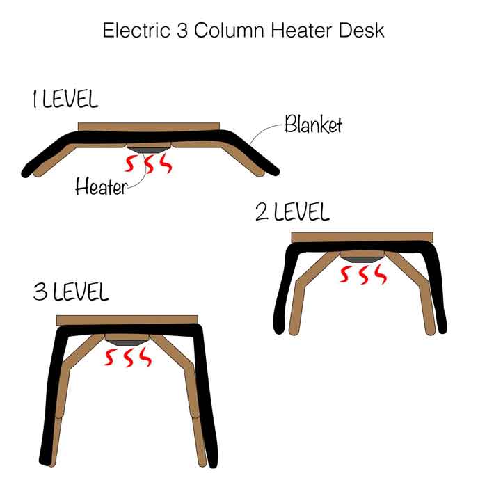
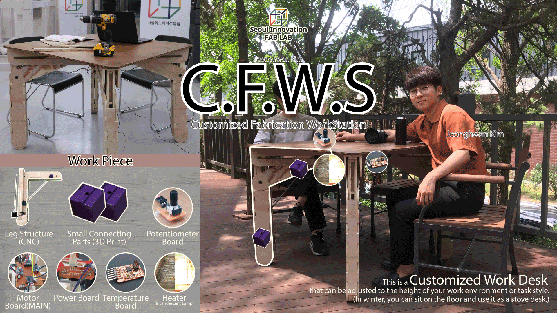
So I decided to make a multi-purpose desk with adjustable height. The height can be used sitting on the floor or sitting down and standing as well. (In addition, I live in a rooftop house, but there is no heating. I will also add a heating system to it.(Referred to Kotatsu))
Features and Functions to Add to a Project
↓important ranking
- Height adjustment (approximately 350mm to 600mm)
- Height adjustment (approximately 600mm to 1100mm) COMPLETE!
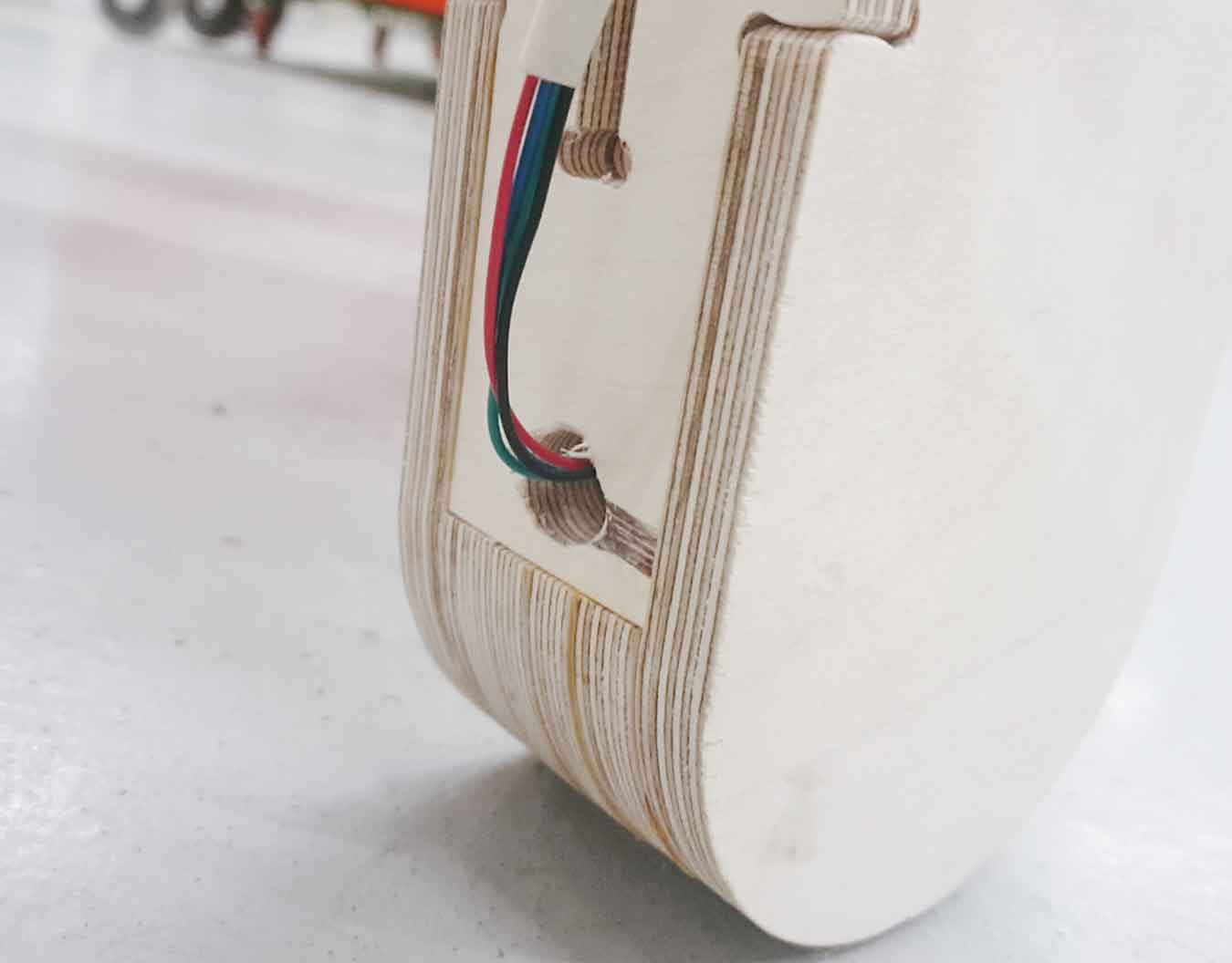
- Bendable legs COMPLETE!
- Height adjuster with potentiometer COMPLETE!
- Heater(heating is incandescent lamp)
- Remote control(about heating)
((Temperature control, on/off,....)) - Capable of inserting a quilt COMPLETE!
Planning
Project Plan
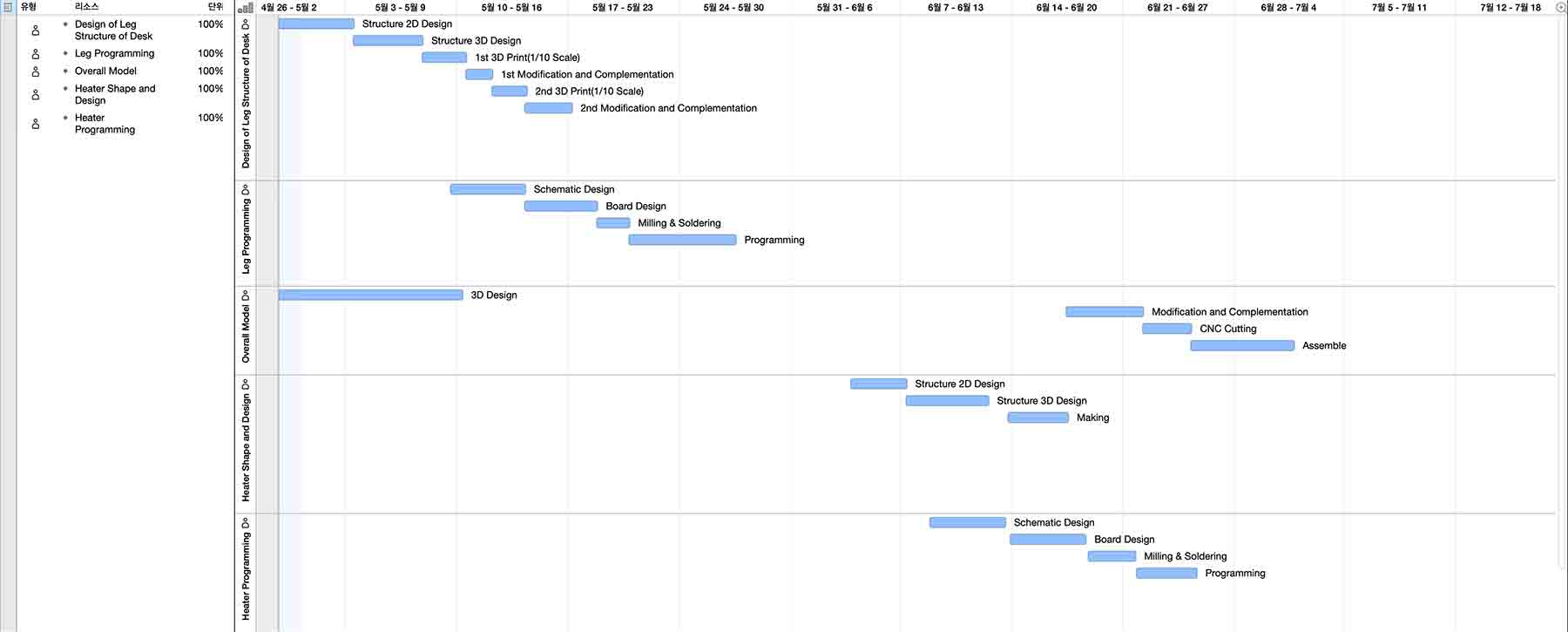
Plan(For The Remaining Two Weeks)
Two weeks were given until the presentation(17-Jun).
I divided my plans into three stages and made a plan to achieve the minimum graduation conditions before the presentation.
The first step is (1)to create an overall desk structure, (2)use potentiometers to set the height adjustment phase up and down stops, and control the four stepper motors. ((3)to move height from 600mm to 1,100mm)
The second step is (1)to add the remaining four motors to move from 350mm to 600mm.
The third step is to (1)build a heating system by adding incandescent lamps (2)to create a board that controls the incandescent lamps.
- What to do to complete the first step
- Test Leg Structure Using a 3D Printer
- Material Purchase & Preparation
- CNC
- 3D Print
- Programming (Input Output Devices)
- Fabrication
- Assemble
Test Leg Structure
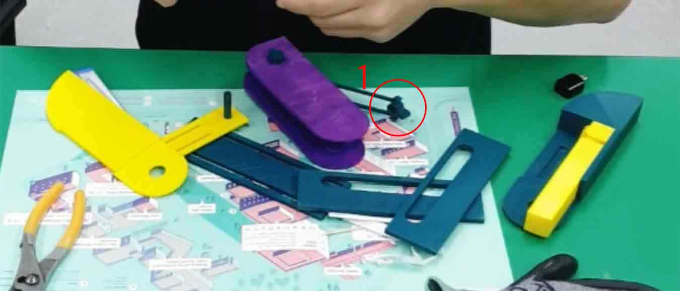
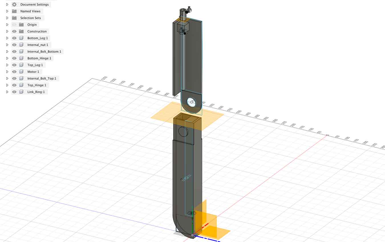
First I needed the conviction that my envisioned leg structure would move smoothly. Therefore, I was going to make a small model leg using 3D printer, check and supplement the problem and proceed with the project.
↓Parts that make up a printed leg using a 3D printer
↓Assembly Video
- What to supplement after the test
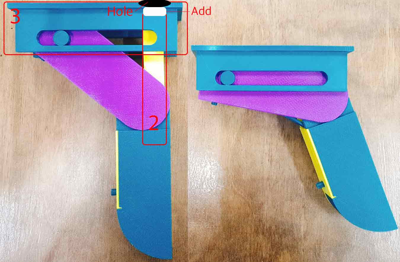
- The movement I wanted came out, but it wasn't soft. The movement of small parts(1) contained in the structure of the leg is restricted. So we're going to increase the length of the movement of the small parts (to make the rail longer).
- (3)The structure that holds the legs is not fixed (2) when the column controlling the height of the legs moves. So I will pierce the place where (3) meets (2) and enter (2) into the hole to keep it from moving.
Material Purchase & Preparation
BOM
Material Type Size&Quantity Price(₩) Link Purchase Status Birch Plywood 12T (1220*2440) 70UDS *2 92,000*2=194,000 Link FABLAB Stepper Motor(NEMA17) *4 23,300*4=93,200 Link BUY Long Bolt 1M *10 22,990 Link BUY Coupling *4 10,000*4=40,000 Link FABLAB
Electronic Parts

- The unit of money is WON(₩) in Korea.
- Almost available on the local open market
Status Preparation
I bought the minimum material to clear step 1.
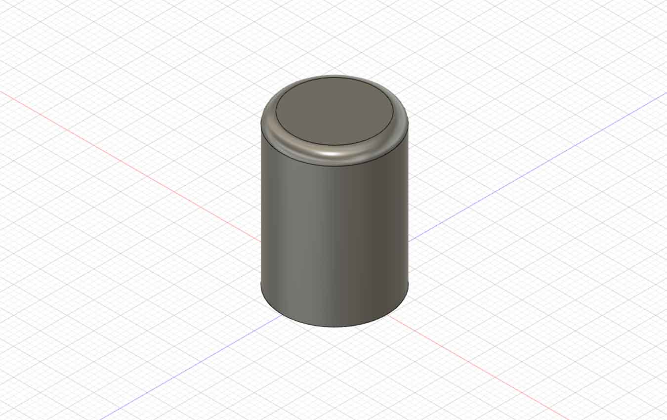
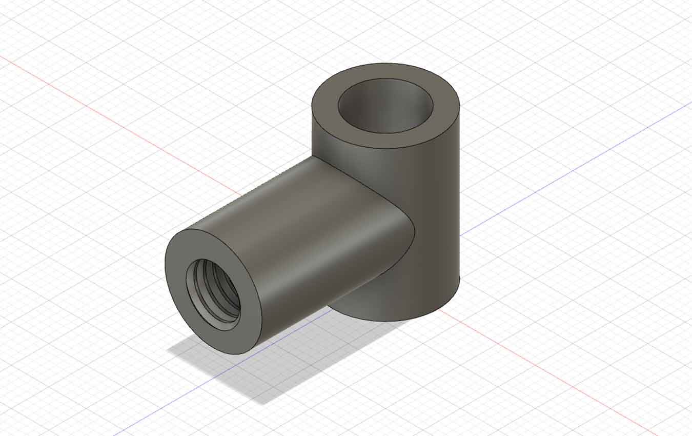
I decided to use the Plywoods and coupling in the Fab Lab. I bought the rest of the ingredients from navimro(openmarket).
But one of the couplings didn't fit the standard. So I tried to Drill it myself using the lathe machine.
Lathe & Turns
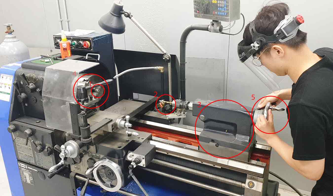
I decided to make the coupling into the shape I need using A. (To extend one hole to 8mm)
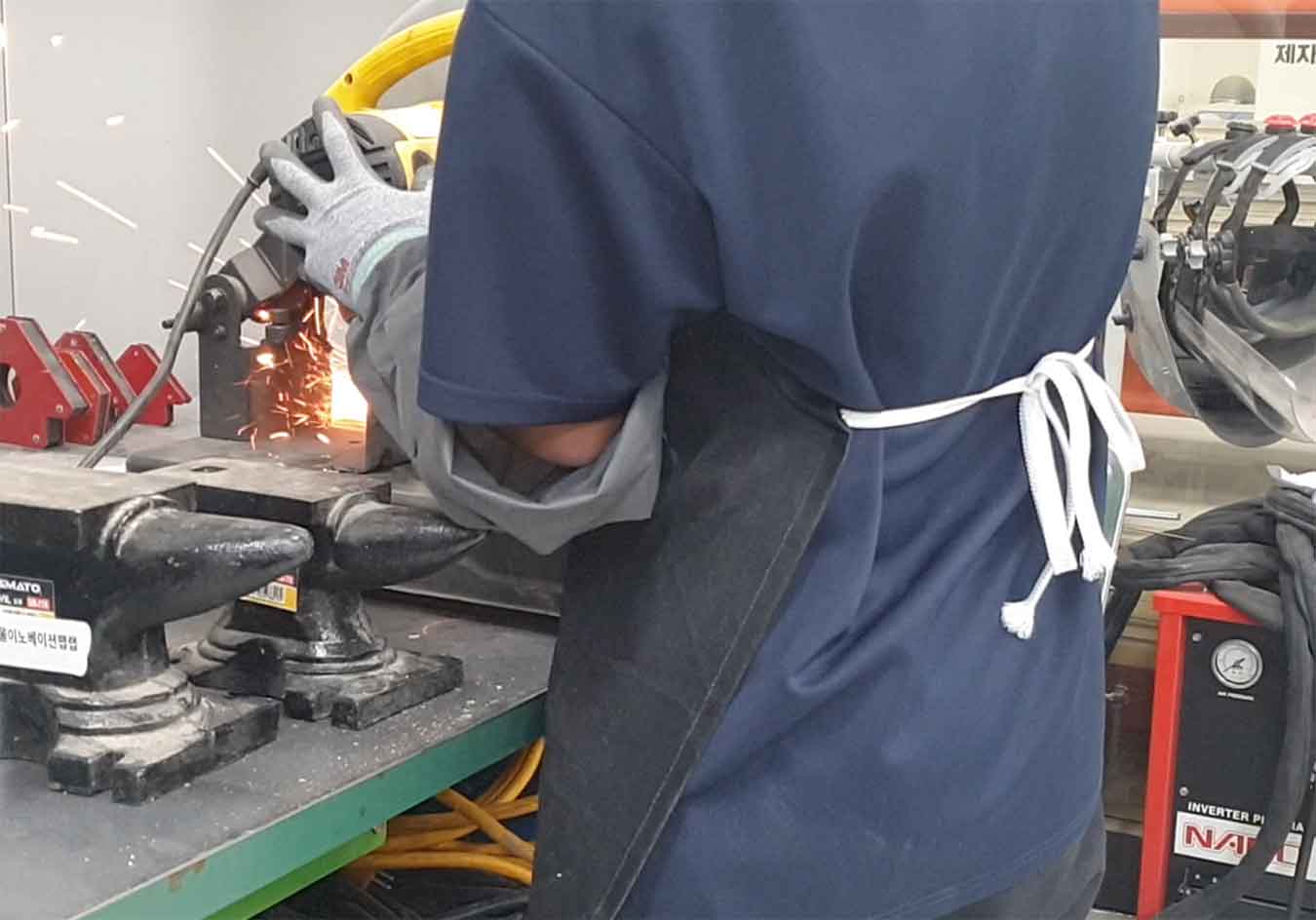
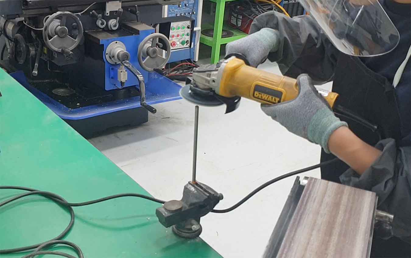
- Here's how
- (Warning)Must wear protective gear to protect your face before you work.
- First, insert the part I want to Drill into 1. (Caution! Make sure that the part is centered and insert it.)
- Insert the Andrew I want into 2.
- Now move C, the torso with B inserted, close to A and secure.
- You are now ready. Press the switch to put into operation 4
- Slowly turn the handle(5) to the depth I want to Drill.
- When finished, turn off the machine and check the results.
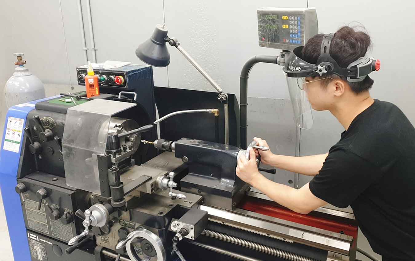
Have a satisfactory result. The first A was really interesting and fun. I thought that using this would produce more diverse results.
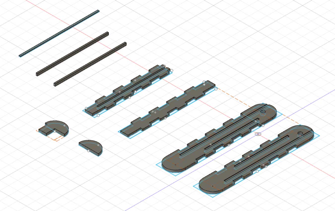
Fusion360 & CNC & Bolt Cutting
I made a design file with Fusion 360 and modeled it. Previously, small legs were made with a 3D printer, making it easier to modify.

I tried to make it into a parametric design as much as possible, but it was very hard.
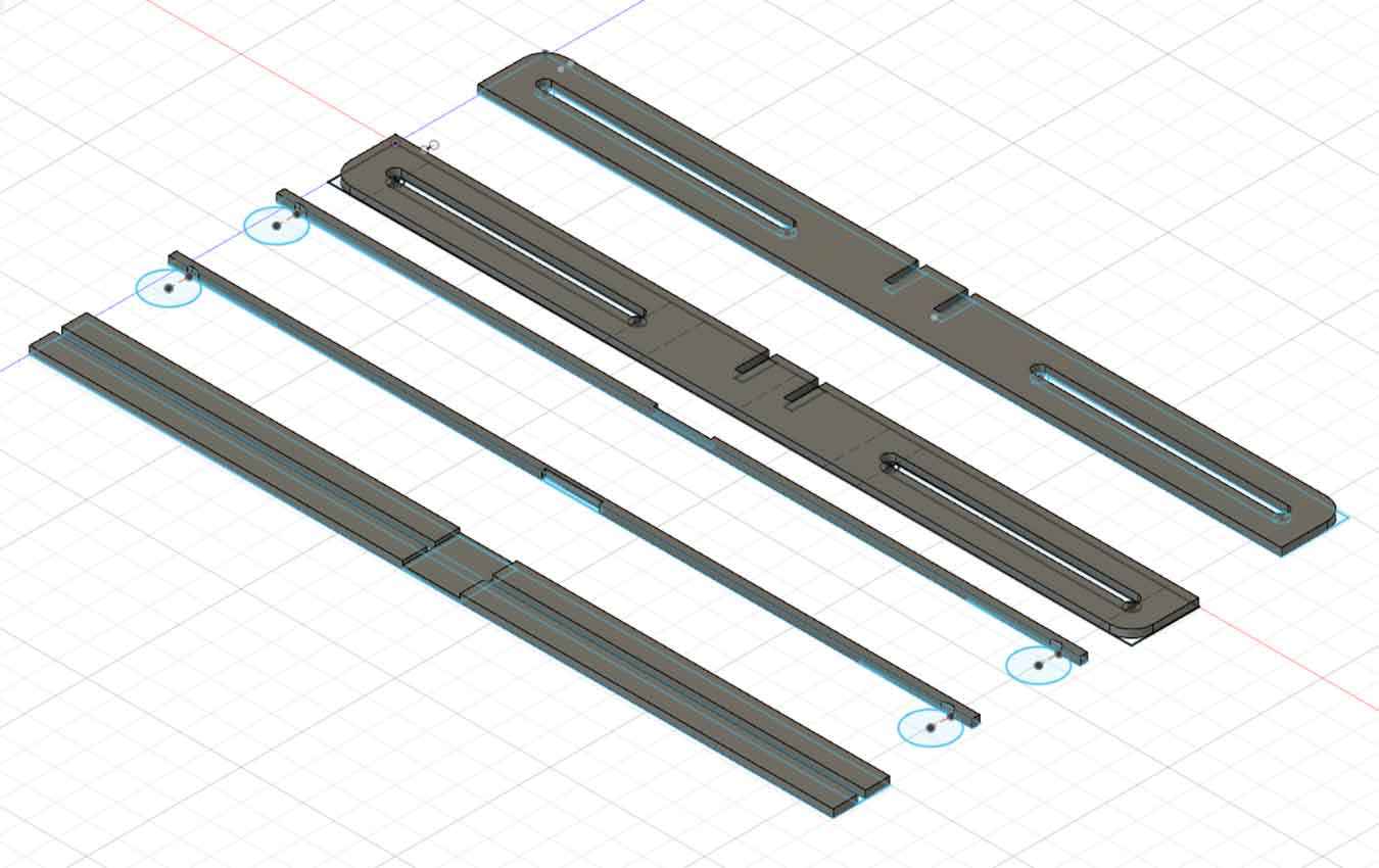
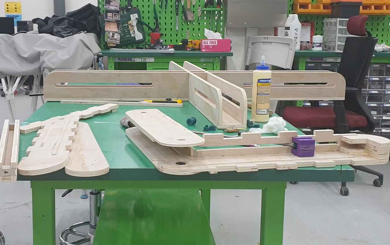
Then I moved the .dxf file to the V-curve, modified it a little bit, and cut it with the shopbot right away. I was going to make one of the four bridges first, then go through a test and make the rest.

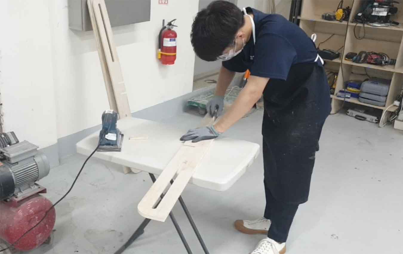
Cutting parts sanded the surface of the tree to move smoothly.
Internal Bolts - 450mm / 2 Leg Parts Connecting Bolts - 400mm
After you test one leg to see if it's moving well,The rest of the legs were assembled.
3D Print
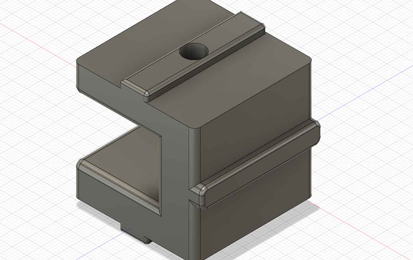

A part that holds the inside and connects each Plywood part. All of them were fused and printed with a 3D printer.

In the order of Z shape, 1, 2 help the movement of long bolts into the bridge. Three and four serve to connect the lower and upper legs. 5 is a part that is fixed with the top plate so that the leg part can be fixed when it is raised. Six is a support for securing the top of a small nut into a column. 7 is the part that connects the long bolts to 1 and 2, and 8 is the part that allows the 7 to enter 1 and 2 and be fixed. 910 is a part that allows the leg to be connected to the leg fixation support.
Programming
It's finally time for programming. This is the work that gave me the most trials while taking the Fab Academy class.
MCU(ATtiny3216)
I had to build a board that included four motors and a potentiometer. To do so, he had to choose MCU,that had many pins to connect to. When I used atiny412, I found the convenience of updi in programming. That's why I wanted to choose mcu with lots of pins with updi pins. So what I found was intint3216.
↓Attiny3216 Pinout

ATtiny3216 Datasheet here
Github about ATtiny3216 here
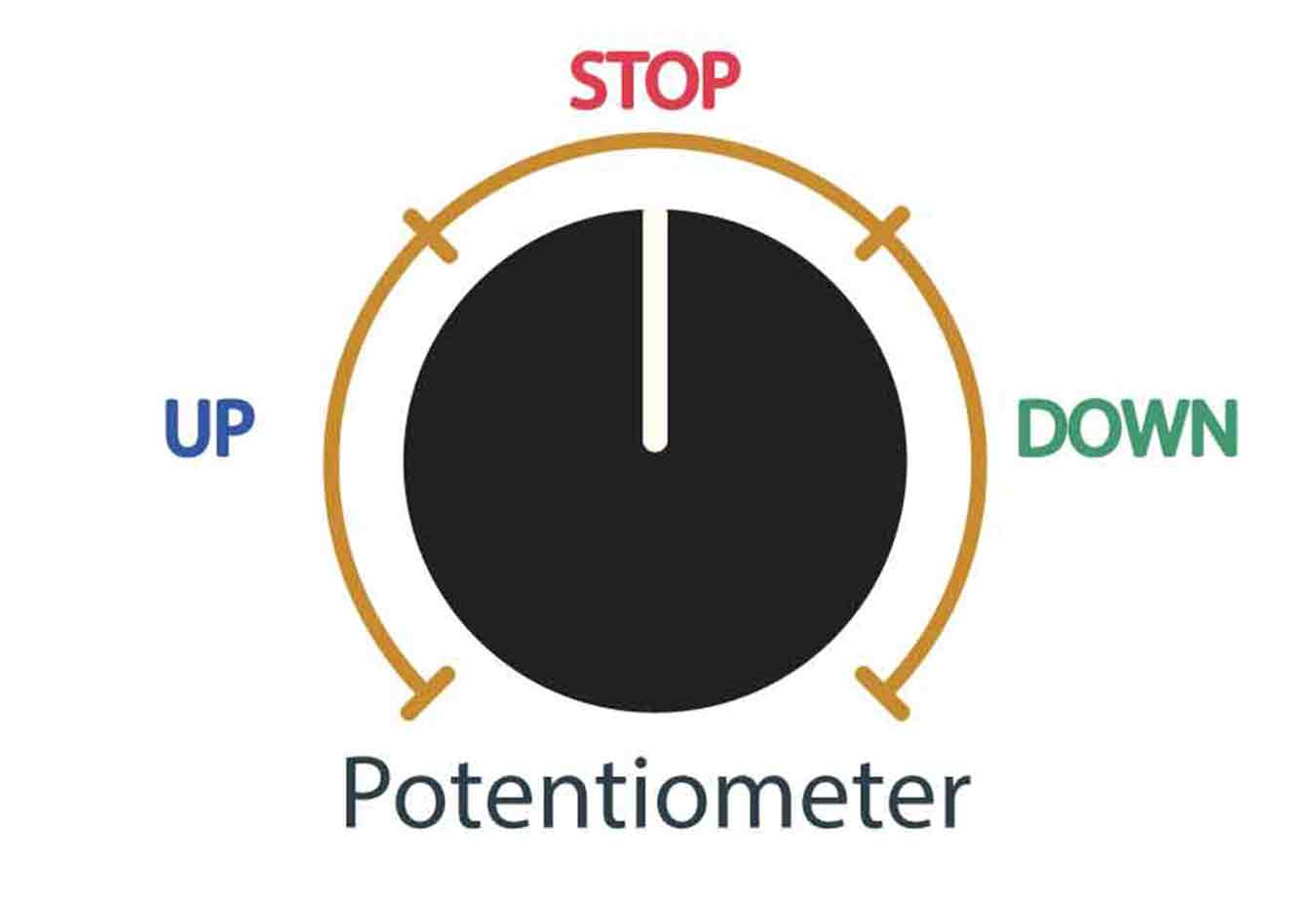
Input Devices(Potentiometer)
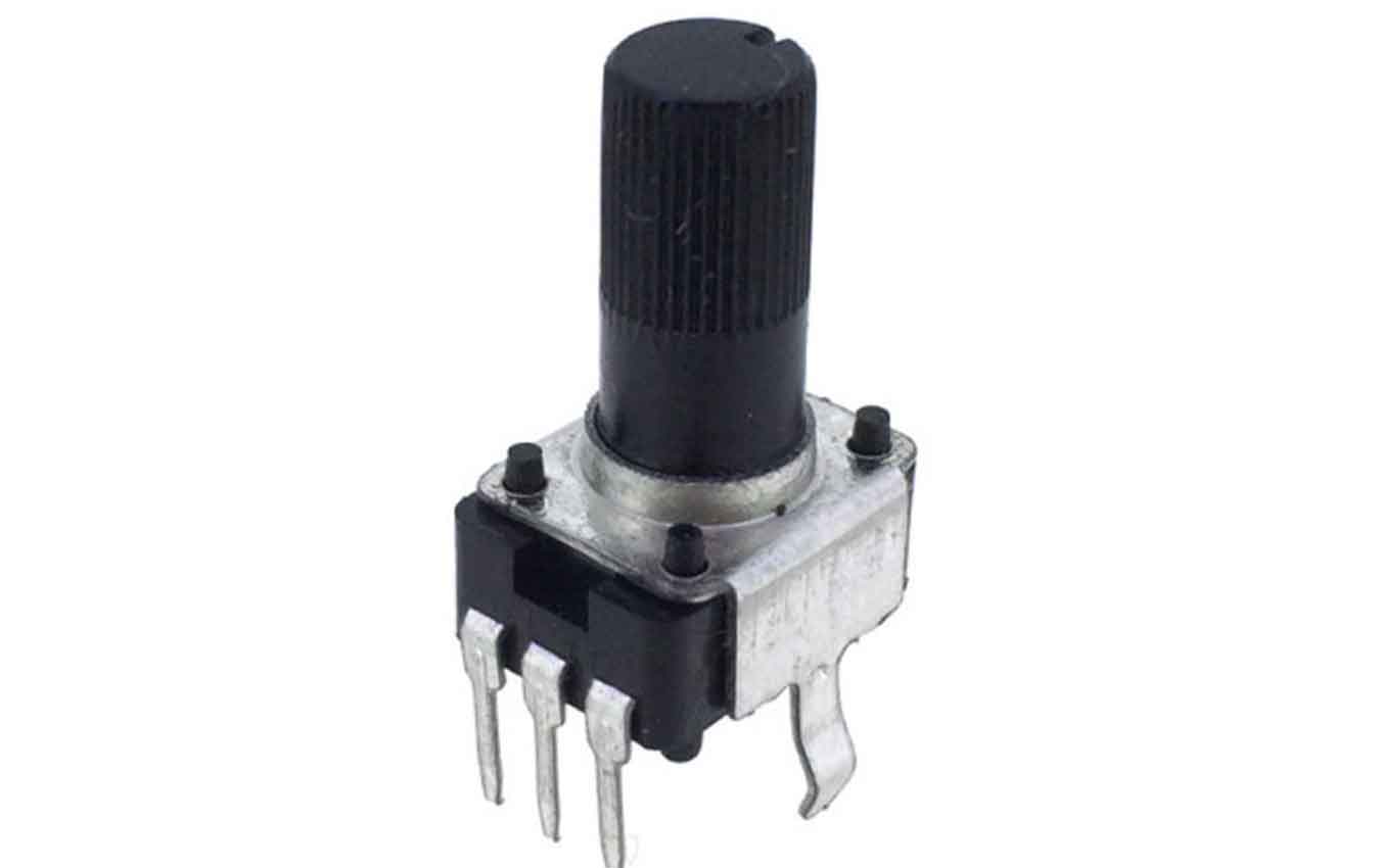
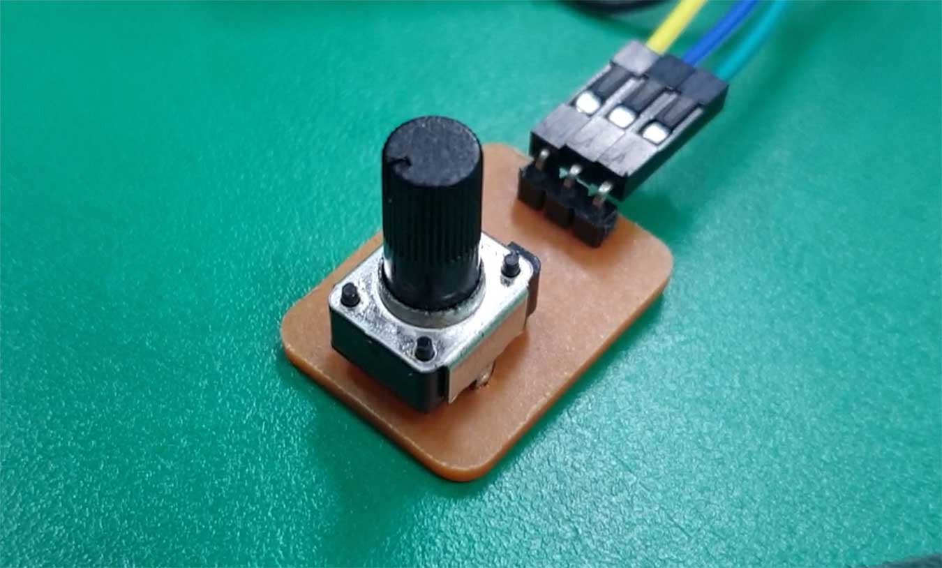
I chose the potentiometer as a way to control the motor. I wanted to make sure that when the motor turns right, the desk goes up, when it turns left, goes down, and when the potentiometer comes in the middle of the range, it stops.
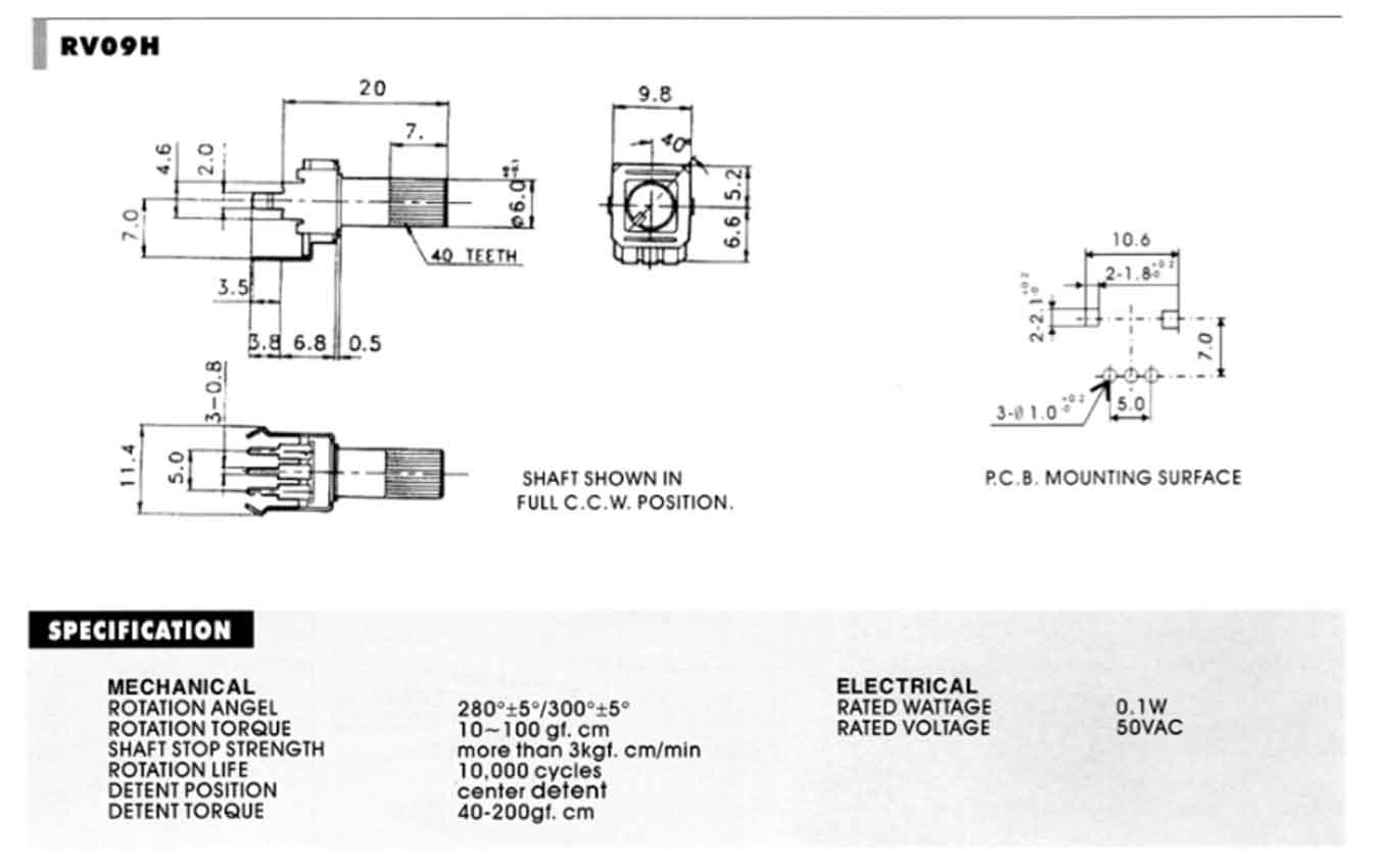
↓rv09h-20sq 10KΩ & Datasheet
Reference Site
I used rv09h-20sq 10KΩ as a potentiometer. There were other types, but just black and simple designs were more attractive.
Output Devices(Stepper Moer-NEMA17)
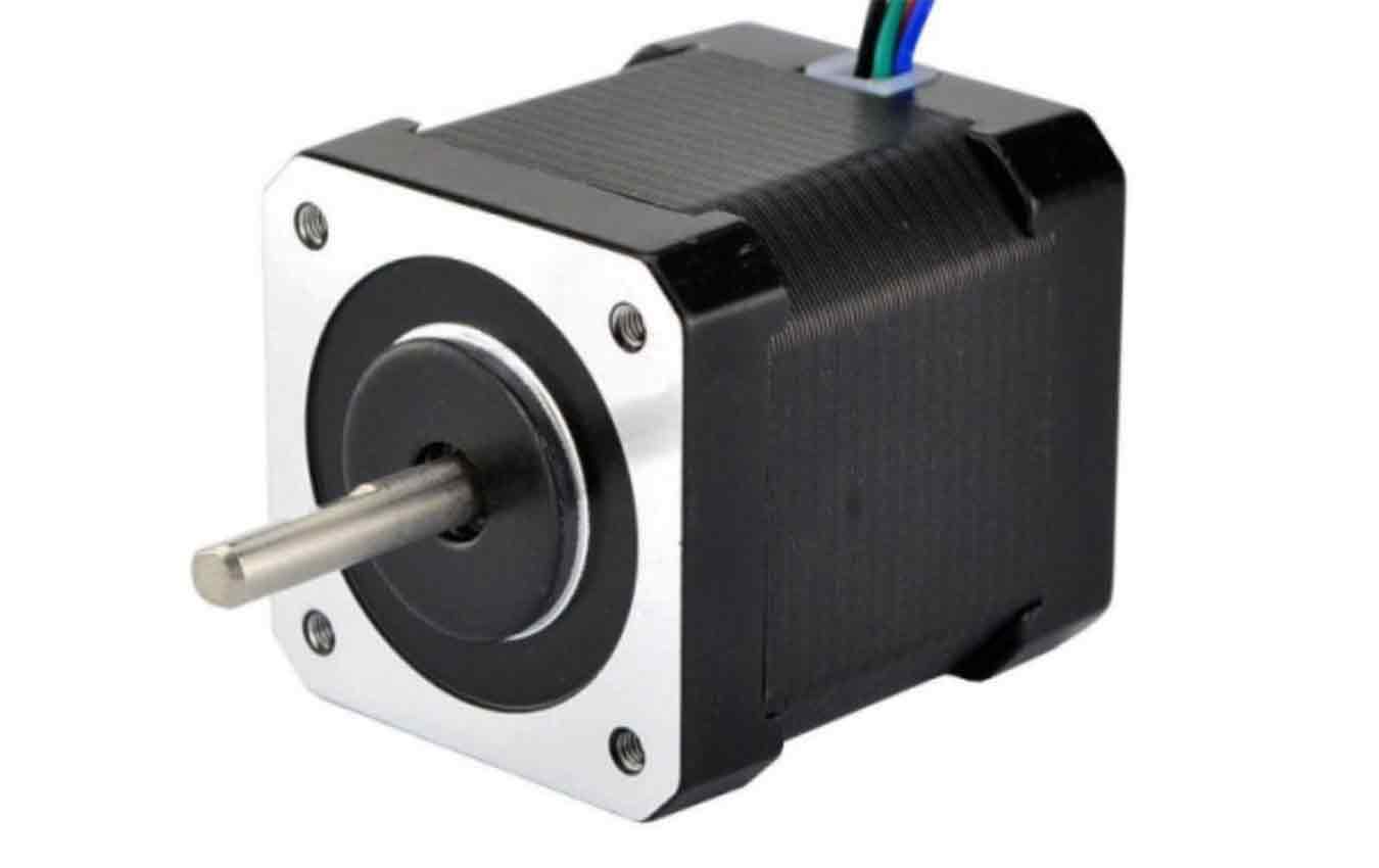
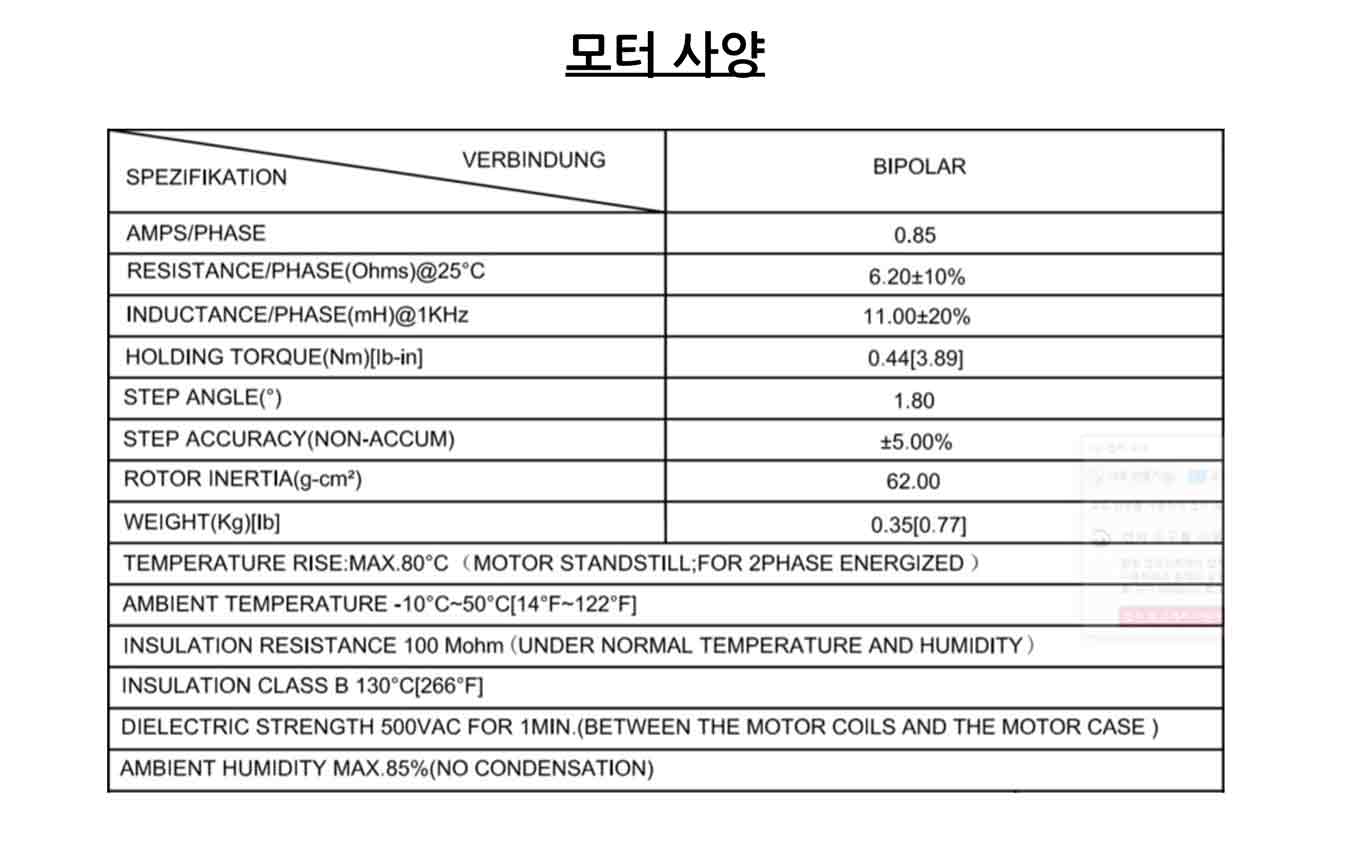
↓42x42x48mm Bipolar 1.8deg 44Ncm (62.3oz.in) 0.85A 5.3V 4 Wires & Datasheet
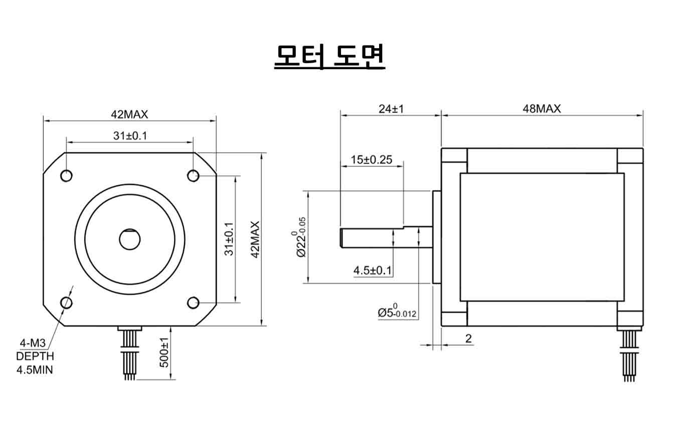

Reference Site
I chose four Stepper Moer-NEMA17 as the motor for the final project. The reason is that it is a motor that I have experienced in output device week, can control 1.8 degrees, and is strong enough to lift a desk.
↓A4988 driver module & Datasheet
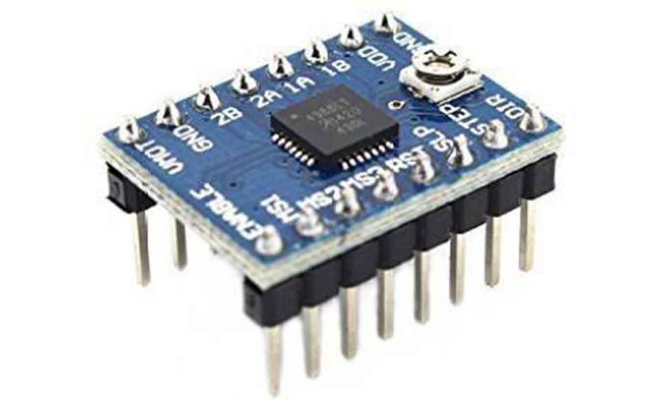
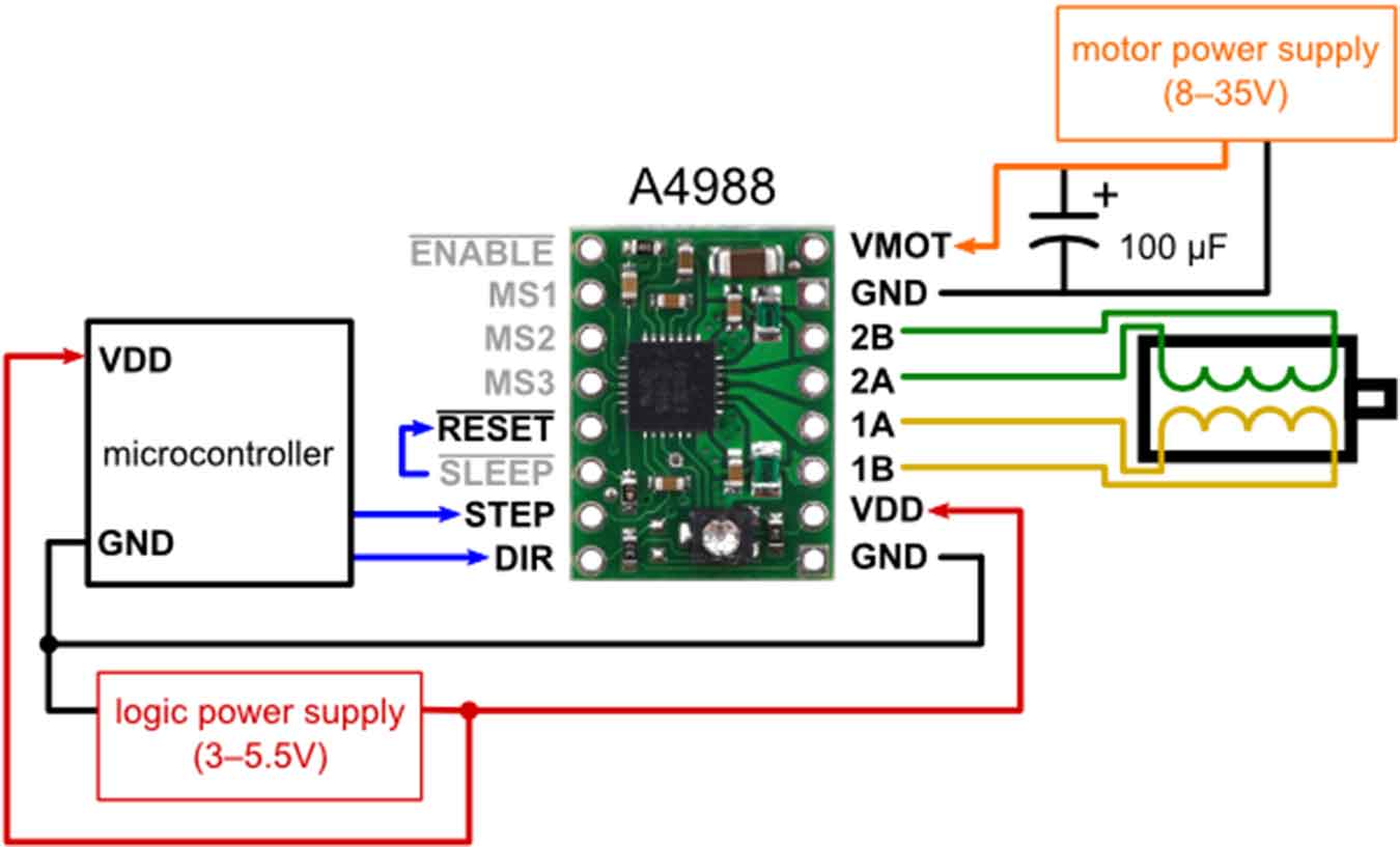
I decided to use A4988 as a motor driver module that controls the motor. It has the advantage of simplifying my work to the fullest extent because it simply needs to be connected to fit the data sheet pin.
Board Design & Milling & Soldering
↓Board Location and Power Supply Plan
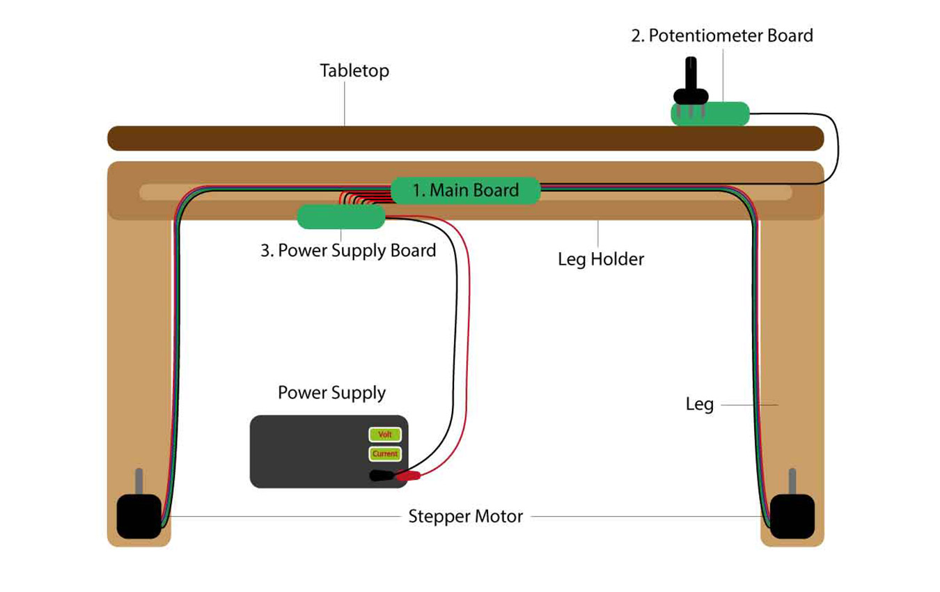
- I decided to make 3 electronic boards.
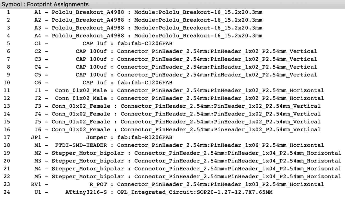
- Main Board
- board with mcu and pin to connect motor driver and motor.
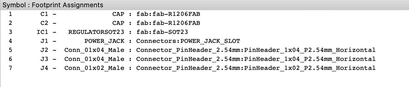
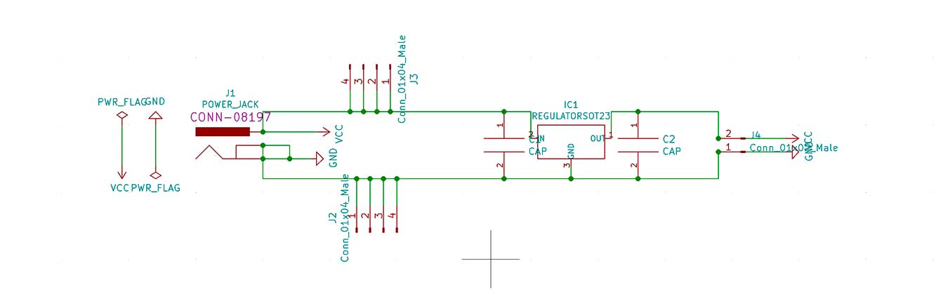
- Power Supply Board
- It is directly connected to power and supplies electricity to the main board. The motor driver connected to the main board transmits 9V and the main board transmits 5V via the transistors.
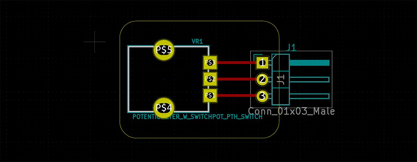
- Potentiometer Board
- board with only pins that can be connected to the potentiometer and main board. I'll put it on the desk to make it easier to control.
- Main Board
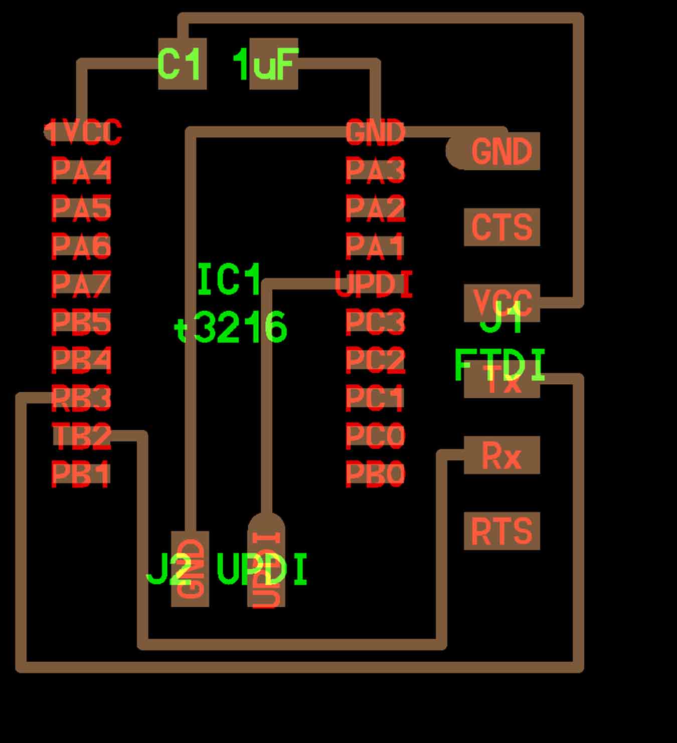
First, I referred to Neil's Hello.t3216.echo to put ATtiny3216 on the main board.
↓Hello.t3216.echo.png
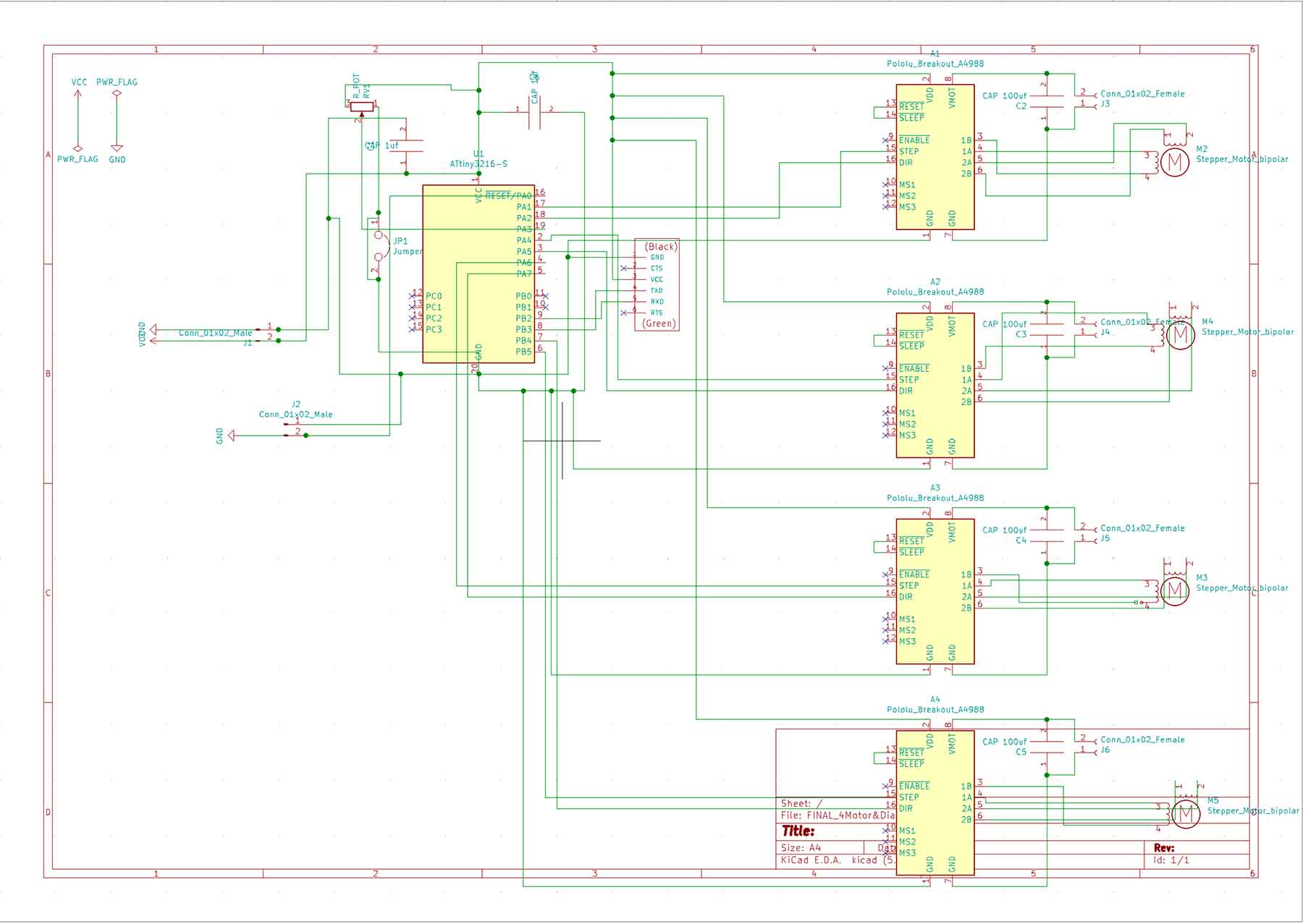
↓Main Board Design

↓Power Supply Board Design

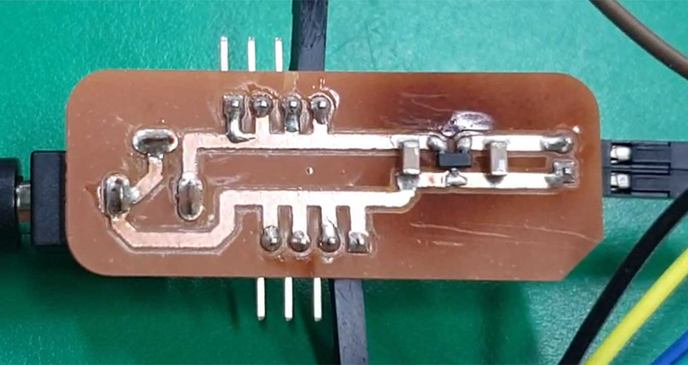
↓Potentiometer Board Design

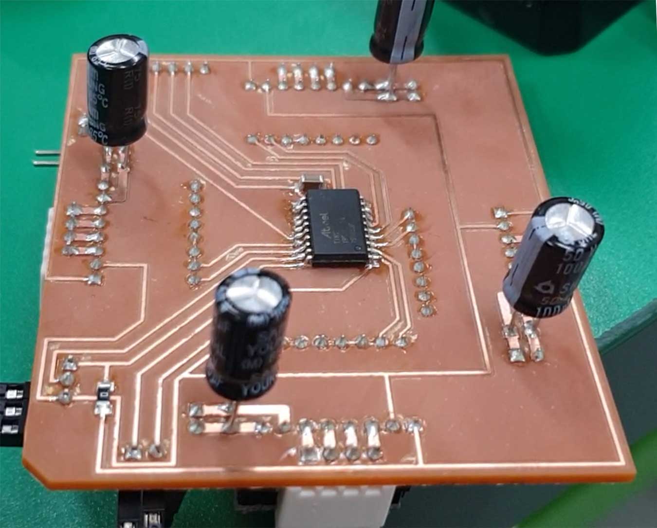
I removed the copper that I didn't need to prevent problems caused by the extra copper (by hand).
- If you do this, there is no problem with the wrong connection when you check it with a multimeter.
Coding
I needed an understanding of the first potentiometer used. So I followed the example of potentiometer in this post and experimented with Arduino.
↓Pot Code in Arduino
void setup() {
 // 초당 9600BPS로 시리얼 통신을 초기화 한다.
 Serial.begin(9600);
}

// the loop routine runs over and over again forever:
void loop() {
 // 아나로그 A0핀을 입력받는다.
 int sensorValue = analogRead(0A);
 // 입력받은 값을 컴퓨터로 보낸다.
 Serial.println(sensorValue);
 delay(100);
}
Next, it is time to test the stepper motor using A4988 Driver.
Reference Site
↓Stepper Motor using A4988 Code in Arduino
int dirPin = 3;
int stepPin = 4;

void setup(){
 pinMode(dirPin,OUTPUT);
 pinMode(stepPin,OUTPUT);
 digitalWrite(dirPin,HIGH);
}

void loop(){
 digitalWrite(stepPin,HIGH);
 delayMicroseconds(500);
 digitalwrite(stepPin,LOW);
 delay(1);
}
I tested the motor control using a potentiometer.
↓Stepper Motor&POT Code in Arduino
int steppin = 3;
int dirpin = 2;
int stepdelay;
void setup() {
 pinMode(steppin, OUTPUT);
 pinMode(dirpin, OUTPUT);
 Serial.begin(9600);

}

void loop() {
 int val = analogRead(A0);
 Serial.println(val);
 if(val<400)  {


 digitalWrite(dirpin, LOW);
 digitalWrite(steppin, HIGH);
 delayMicroseconds(stepdelay);
 digitalWrite(steppin, LOW);
 delayMicroseconds(stepdelay);


 }else if(val>600)  {

   digitalWrite(dirpin, HIGH);
   digitalWrite(steppin, HIGH);
   delayMicroseconds(stepdelay);
   digitalWrite(steppin, LOW);
   delayMicroseconds(stepdelay);

 }else{
   digitalWrite(dirpin, LOW);
   digitalWrite(steppin, HIGH);
   delayMicroseconds(stepdelay);
   digitalWrite(steppin, HIGH);
   delayMicroseconds(stepdelay);
 }
}
After writing the Arduino code by referring to Mr Innovative's the video, the sketch was modified to divide the rank of the potentiometer into three zones using if Syntax.
↓Test Video
FINAL Code
Now it's time to write the last code. To control the four motors with a potentiometer, three different motor roles were added to each section.
↓FINAL Code(Ctrl 4 Motor) in Arduino
int Asteppin = 0;
int Adirpin = 1;
int Bsteppin = 2;
int Bdirpin = 3;
int Csteppin = 4;
int Cdirpin = 5;
int Dsteppin = 14;
int Ddirpin = 15;
int stepdelay = 1000;
void setup() {
 pinMode(Asteppin, OUTPUT);
 pinMode(Adirpin, OUTPUT);
 pinMode(Bsteppin, OUTPUT);
 pinMode(Bdirpin, OUTPUT);
 pinMode(Csteppin, OUTPUT);
 pinMode(Cdirpin, OUTPUT);
 pinMode(Dsteppin, OUTPUT);
 pinMode(Ddirpin, OUTPUT);
 Serial.begin(9600);

}

void loop() {
int val = analogRead(16);
Serial.println(val);if(val<400)  {


  digitalWrite(Adirpin, LOW);
  digitalWrite(Bdirpin, LOW);
  digitalWrite(Cdirpin, LOW);
  digitalWrite(Ddirpin, LOW);//direction pin either LOW or HIGH to move in either direction.
  digitalWrite(Asteppin, HIGH);
  digitalWrite(Bsteppin, HIGH);
  digitalWrite(Csteppin, HIGH);
  digitalWrite(Dsteppin, HIGH);
  delayMicroseconds(stepdelay);
  digitalWrite(Asteppin, LOW);
  digitalWrite(Bsteppin, LOW);
  digitalWrite(Csteppin, LOW);
  digitalWrite(Dsteppin, LOW);
  delayMicroseconds(stepdelay);


}else if(val>600)  {

  digitalWrite(Adirpin, HIGH);
  digitalWrite(Bdirpin, HIGH);
  digitalWrite(Cdirpin, HIGH);
  digitalWrite(Ddirpin, HIGH);
  digitalWrite(Asteppin, HIGH);
  digitalWrite(Bsteppin, HIGH);
  digitalWrite(Csteppin, HIGH);
  digitalWrite(Dsteppin, HIGH);
  delayMicroseconds(stepdelay);
  digitalWrite(Asteppin, LOW);
  digitalWrite(Bsteppin, LOW);
  digitalWrite(Csteppin, LOW);
  digitalWrite(Dsteppin, LOW);
  delayMicroseconds(stepdelay);

}else{
  digitalWrite(Adirpin, LOW);
  digitalWrite(Bdirpin, LOW);
  digitalWrite(Cdirpin, LOW);
  digitalWrite(Ddirpin, LOW);
  digitalWrite(Asteppin, HIGH);
  digitalWrite(Bsteppin, HIGH);
  digitalWrite(Csteppin, HIGH);
  digitalWrite(Dsteppin, HIGH);
  delayMicroseconds(stepdelay);
  digitalWrite(Asteppin, HIGH);
  digitalWrite(Bsteppin, HIGH);
  digitalWrite(Csteppin, HIGH);
  digitalWrite(Dsteppin, HIGH);
  delayMicroseconds(stepdelay);
}
}
Assemble
↓1 Leg Test
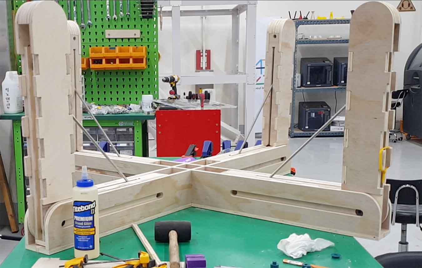
First, I combined the structure that holds the legs and one leg to test whether the legs move up and down well. The result is a success! Next step.
↓4 Leg Test
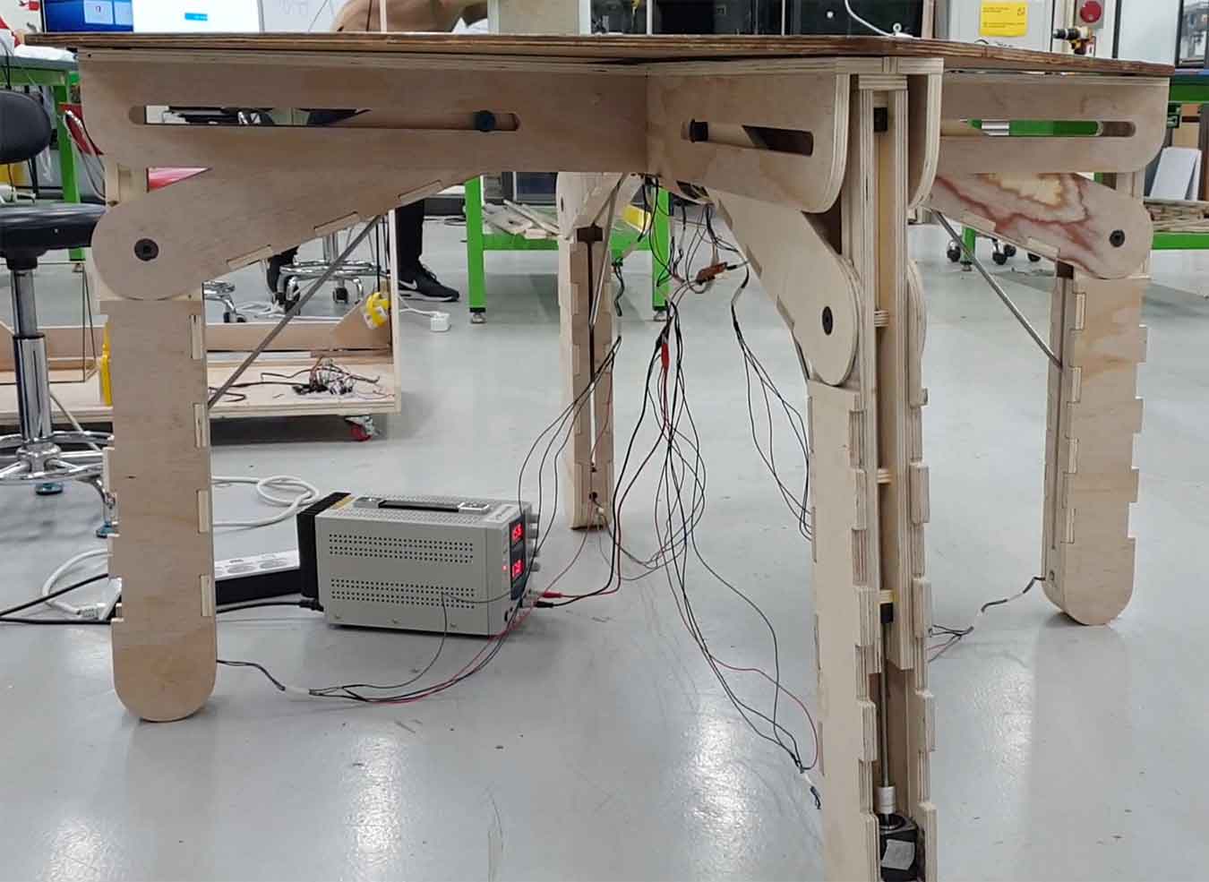
Now combine the four legs and add a completed board to test if the legs move well. The result is... a success! Yay!
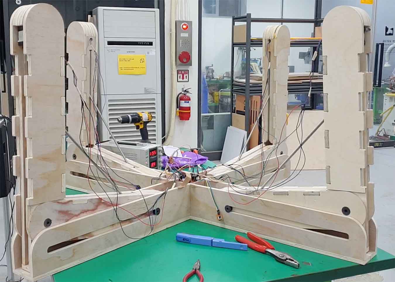
It's the last time. I flipped the desk over and put it down on the floor to make sure it was moving well. It's finally done!
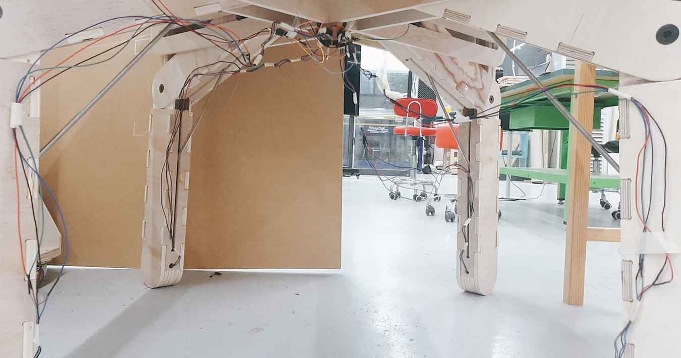
I let my board come in the middle under the desk, drilled a line from the motor at the bottom of the bridge, and connected it with the board. It doesn't look good in appearance. I'm going to tell you how to put the line in, and how to clean it out. I will study more about how to take it out.
Slide & Video
Slide
Video
*Music) Tobu - Candyland
Anyone that aided my success over the past 6 months.
Neil Gershenfeld, taught me about my class, my teacher Craig, who always helped me at Fab Lab until 22:00, my colleagues, Jihwan, Seokmin, Hyunho, Yoonjae, and fab officials (Hyebin Gu, Jenny) , Etc..), the Haru(Restaurant) and GS25 that solved my strong meals, my girlfriend Healin Kim, who gave me a lot of encouragement and comfort, Chan Kim, Hyunghwa Choi, who also helped a lot. Tareung helped me to get home comfortably. Fab seniors who put many trials and errors first, Local classmates, regional review participants (Kamakura and Shanghai, etc.) who gave a lot of feedback and support. Thanks everyone~!
Things planned by 10. Applications and Implications
what questions need to be answered?
- What else can be used as a heater besides incandescent bulbs?
→ I couldn't answer this question. - What mechanical structure can I make the movement I want?
→ This was solved with a small leg model printed on a 3D printer, which I made at the beginning. - What should I do to make the legs of the desk move smoothly?
→ A suitable gap is needed between playwoods. Also, the shape of the leg should be accurate according to the figures I set. (If you over-tighten the clamp, you will not get the desired figure. You have to be careful because problems arise from here. )
- What else can be used as a heater besides incandescent bulbs?
- what has worked? what hasn't?
- As far as I've made it
- The four motors work well.
- Depending on the potentiometer, the motor will operate well.
- The legs of the desk move up and down.
- Hasn't
- It does not go up or down horizontally.
- The movement of the two legs of the desk is not smooth.
- As far as I've made it
How was it evaluated?
- 75 percent of the success. It means a lot. Mechanically, the desk can move from 350mm to 1100mm. Many possibilities are open. You can try more later with this desk.
- what are the implications?
- We've made a new discovery. Many people can see this and develop better works. Also, I can develop more or start a business with this. It's a success, and there will be a better desk in the future.
Link
- Slide here
- Video here
- Project Development Work Process here
Link to weekly modules
- Motor module here
- Temperature sensor module here
File
Fusion360
- FINAL v12.f3d File here
- Top Leg.dxf File here
- Bottom Leg.dxf File here
- Colum.dxf File here
3D Print
- Center_Bottom.stl File hereX4
- Center_Top.stl File hereX4
- Extra Parts ver2 1.stl File hereX4
- Extra Parts ver2 2.stl File hereX4
- Rail_Pillar1.stl File hereX4
- Rail_Pillar2.stl File hereX4
- Pillar_Holder.stl File hereX8
- Pillar.stl File hereX8
- Nut_Hold.stl File hereX4
- hold top.stl File hereX4
KiCad
- Main Board.sch File here
- Main Board.brd File here
- Main Board.drl File here
- Main Board-F_Cu.gbr File here
- Main Board-Edge_Cuts.gbr File here
- Power Supply Board.sch File here
- Power Supply Board.brd File here
- Power Supply Board.drl File here
- Power Supply Board-F_Cu.gbr File here
- Power Supply Board-Edge_Cuts.gbr File here
- Potentiometer Board.sch File here
- Potentiometer Board.brd File here
- Potentiometer Board.drl File here
- Potentiometer Board-F_Cu.gbr File here
- Potentiometer Board-Edge_Cuts.gbr File here
Arduino
- Potentiometer.ino File here
- Stepper Motor_Use_A4988.ino File here
- FINAL_Motor&Pot.ino File here