Week 8: embedded programming
individual assignment:
read a microcontroller data sheet, program your board to do something, with as many different programming languages and programming environments as possible
group assignment:
compare the performance and development workflows for other architectures
Group assignment
Worked with Achille, Hannu, and Jari in group assignment this week. For the assignment we compared the performance and development workflows for Arduino UNO R3 and Atmel Nucleo STM32F401 boards.
Whole documentation of our group can be found from Hannu's page.
Individual assignment
Datasheet
I chose ATTINY412's datasheet for this task. It is in the board made at week 6. Microchip's website has full datasheet and also the short version of it.
Main features:
- It has 8-bit AVR RISC CPU capable running up to 20MHz
- CPU uses Harvard architecture with separate buses for program and data
- Has following amount of memories: 256B SRAM, 4KB Flash and 128KB EEPROM
- Has 8-pin layout
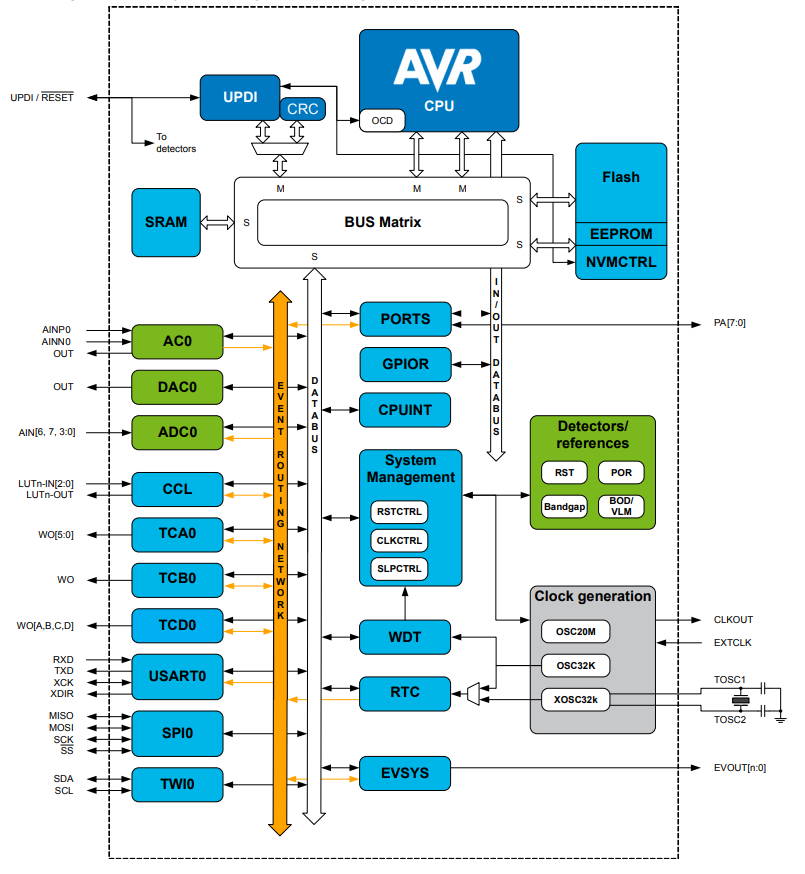
Block diagram of ATTINY412.
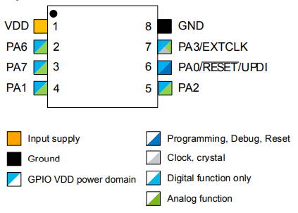
8-pin SOIC (Small outline integrated circuit). External programming of Microcontroller is done through UPDI 1W interface. The RESET-pin (6) is used for the programming.
Programming
I started by looking from previous years since our lab was closed for this week. Most of people had used Button from Arduino's examples. There was one difference now since we used another microcontroller. I am using UPDI programmer from week 4 to program ATTINY412 board from week 6 for this week's assignment. First I went through ATTINY412 board's schematic to check which pins I had used for button and led.
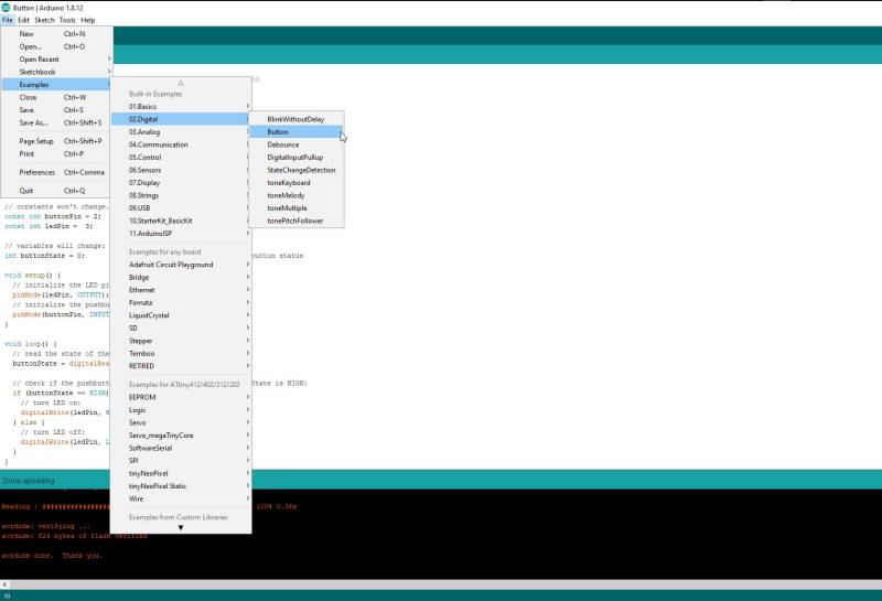
To open Button-code click File -> Examples -> 02.Digital -> Button.
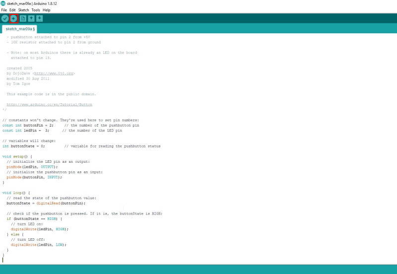
I set ButtonPin to 2 and ledPin to 3 which were pins from my schematic. After this I pressed the upload button from the top.
After uploading I tried with the FTDI cable if it works, but nothing happens.
At this point local instructor Ari reminded that analog/digital pin numbers are not same as shown in the datasheet. From SpenceKonde's github it is possible to check right pin numbers. This turned out to be very useful for upcoming week as well.
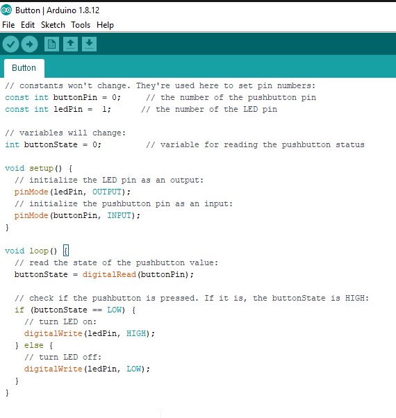
Changed button pin for 0 and led pin to 1. After this it started working correctly.
A short video to show how it works.
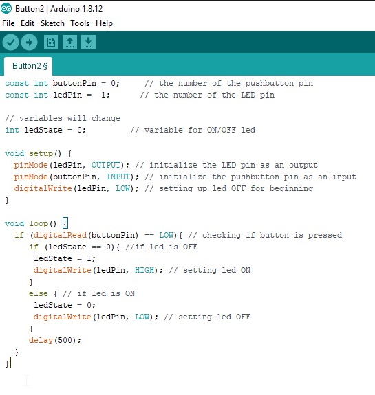
Another common use for a button would be to keep a led (or something similar) ON or OFF with a single press. This was done mostly with the code from earlier button, but added an if-statement in to the loop.
A short video to show how it works.
Atmel studio 7
Atmel studio 7 is integrated development platform (IDP). It is used for developing and debugging all AVR® and SAM microcontroller applications.
I followed Simon Merrett's project page about how to set up Atmel Studio for ATtiny and how to add jtag2updi as a programmer.
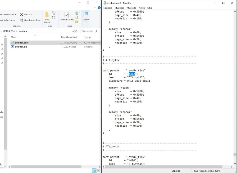
First I downloaded and extracted avrdude 6.3 (avrdude-6.3-mingw32.zip). Avrdude 6.3 does not support ATtiny412 so I had to change avrdude.conf with one from ElTangas' jtag2updi. It's easy to check if .conf-file has the ATtiny412 with Notepad.
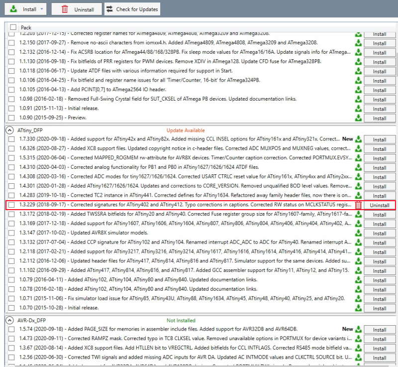
Next I checked that 1.3.229 under ATtiny_DFP was installed. In my case it was already installed on both of my computers.
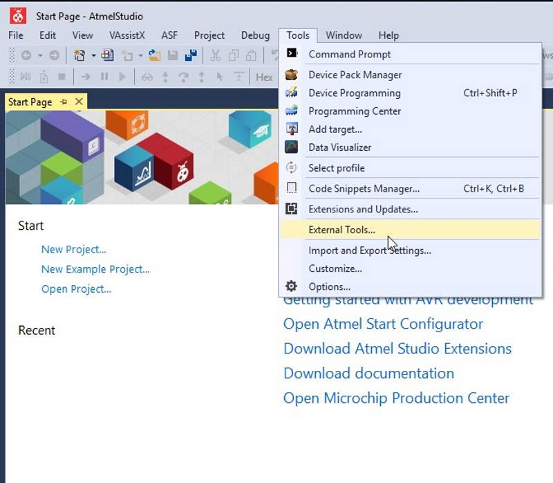
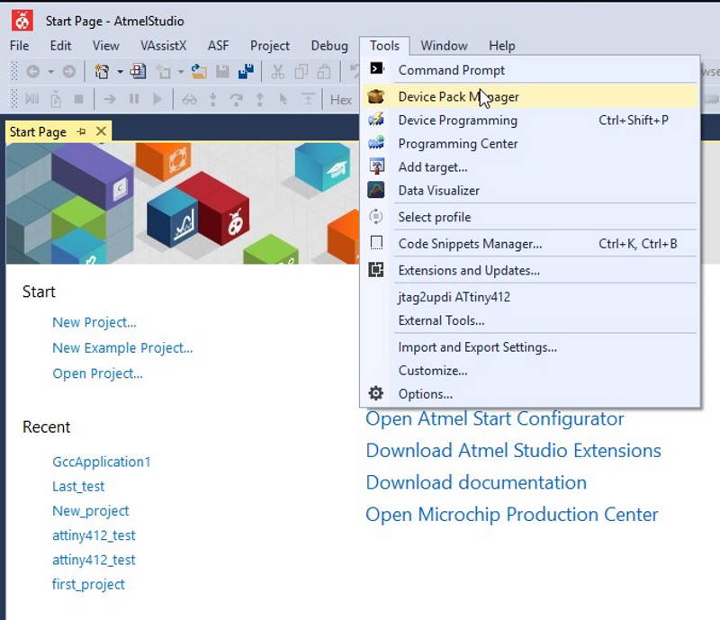
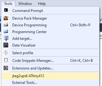
Next added jtag2updi as a programmer on External Tools.
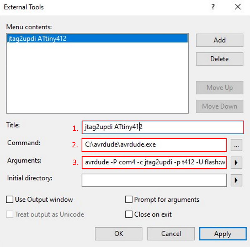
- First add Title, this can be anything as long as it's recognizable for the user.
- On Command add path to avrdude.exe.
- Arguments is the most complex of these. I copied mostly same settings as Simon had used and only changed com to match mine and t412 which I checked from the avrdude.conf.
avrdude -P com4 -c jtag2updi -p t412 -U flash:w:$(ProjectDir)Debug\$(TargetName).hex:i
From the checkboxes pick ones you want. I didn't want to use any of them.
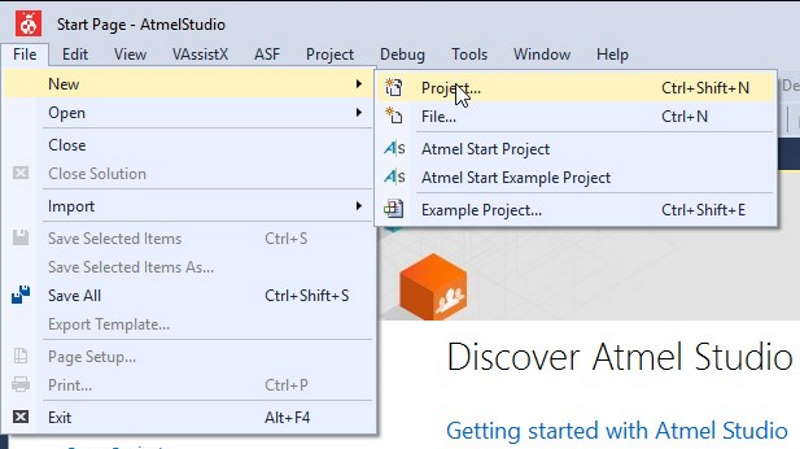
Finally could start the programming. First I started a new project. This can be done by opening File-menu -> New -> Project.
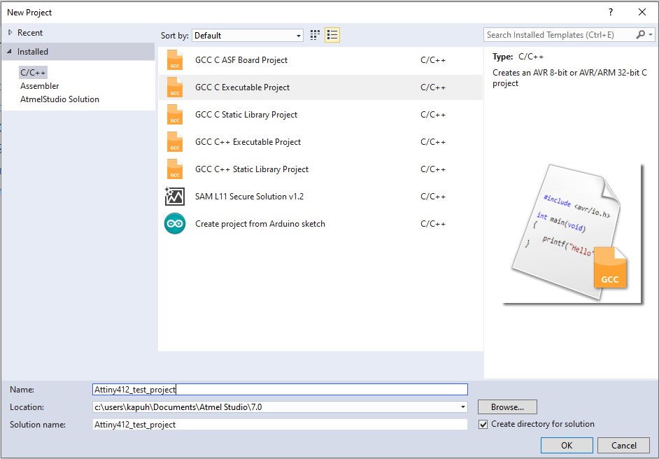
Seleced GCC C Executable project and filled the required fields.
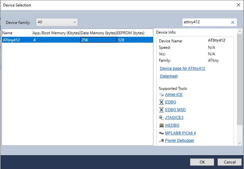
Next search the microcontroller you are using in the project. I was using ATtiny412 so searched and selected it.
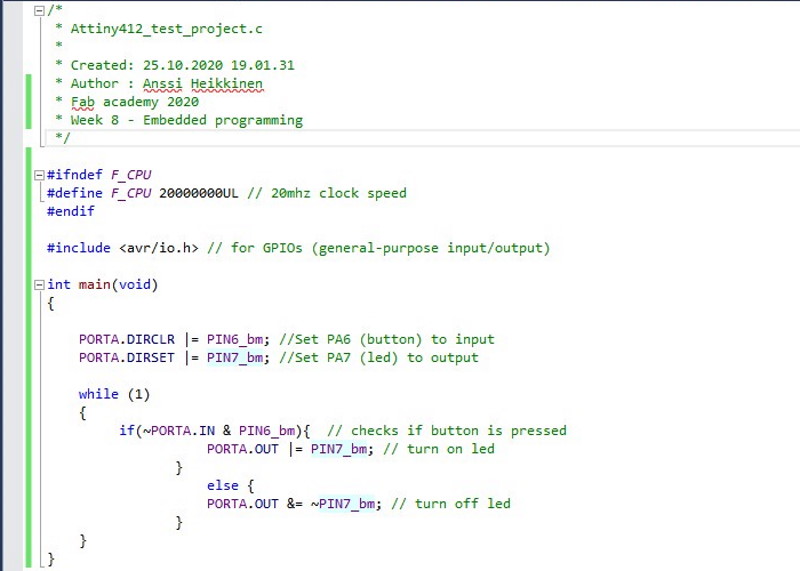
This program is a simple one and still took a lot more effort and research than more complex Arduino programs I have made :D It will only check if the button is pressed (PA6) and turns the led (PA7) on if it's. I seached through a lot of information about how to use the C to make a program and some links to the sources which I remembered to save can be found from below.
- Microchip.com: ATtiny212/412 datasheet, section 16
- Simon Merrett's project page: Open a Project in Atmel studio, Compile and Upload Code
- AVRfreaks forum thread: Getting started ATtiny 1 & 0 series
- Microchip.com: Getting started with GPIO
- tutorialspoint.com:C programming - operators
Here the struggle started for me. For some reason I am not able to build succesfully a program on my work laptop and program the board even though I am using exactly same settings and same steps as on my own computer. Unfortunately, I first tried to do this on the laptop and started to get frustrated because could not find a fix from internet that I could use. Only positive side of this is that I went through multiple forum threads and guides which helped me to understand all of this a little bit better.
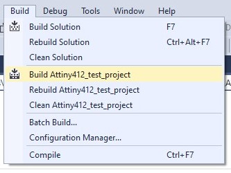
When the program is ready, use the Build option to compile it. This should open the Output window at the bottom of the screen. On a succesful ran it should post a message which states that the build succeeded.
Next press the programmer which was set up previously, in my case jtag2updi ATtiny412.
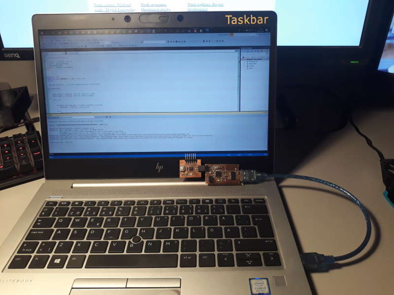
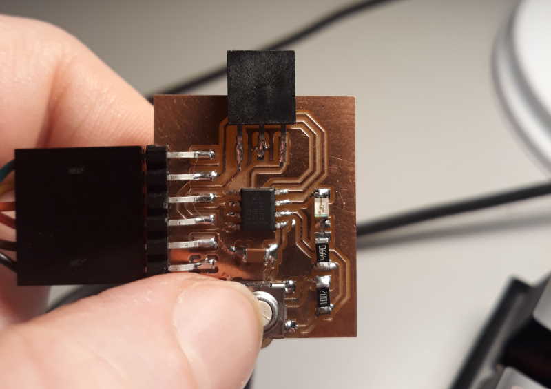
Quickly showing the setup, using programmer from week 4 and board from week 6.
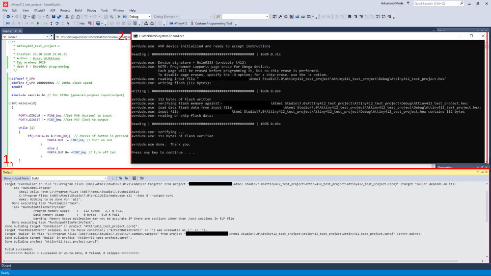
Was able to build and program the board succesfully.
- Here is the output section. In this case it cointains the information after the build.
- Here is the programming.
Short clip showing the programming and board in the action after succesfully programming it.
Files
Button.inoButton2.ino
attiny412_button_led.c