Week 4: electronics production
Week four's assignments is to make in-circuit programmer by milling and stuffing the PCB and test it. For group assignment characterize the design rules for your PCB production process
Group assignment
Worked with Achille, Hannu, and Jari on this week's group assignment. This week our assignment was to characterize the design rules for our PCB production process. In this group assignment learnt about milling and how to use different end mills depending on situation.
Whole documentation of our group can be found from Hannus' site.
Setting up files
For this week's assignment we used fablab Oulu's board. It is updi programmer that utilizes Arduino IDE to program AVR microcontroller.
We started by creating .rml-files with mods. There is 3 files: calibration, traces and outlines.
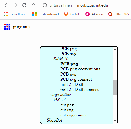
We started by opening right program in mods. Fab lab Oulu have Roland's SRM-20 milling machines.
- start by right-clicking on any part of screen
- select Programs
- select Open server program
- scroll downwards till you find Roland SRM-20 and choose PCB png under it
After this it is time to choose file you want to create. In this case I am choosing calibration file first.
Calibration and Traces
Calibration and traces will be milled with 0.2-0.5mm V end mill.
- First press select file and invert it (do not invert traces-file)
- Choose mill tracer (1/64)
- Set tool diamaterer to 0.23mm and offset number to 5
- Set origin to 0 in X, Y and Z
- Delete Websocket device and add new module by right-clicking -> modules -> open server program -> file:save
- Make line between outputs and inputs by clicking file and file (objects)
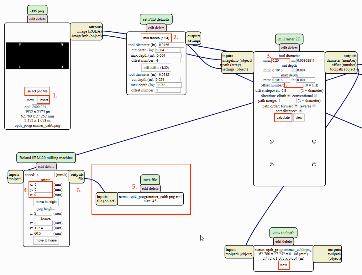
After settings are done, press calculate. To see toolpath press view under View toolpaths.
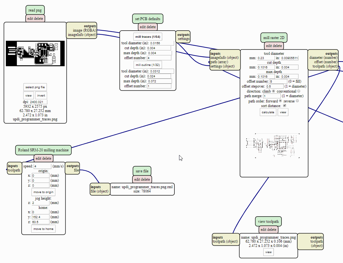
Traces can be created by using same settings except the image do not have to inverted.
Outlines
Outlines require small tuning into settings. Also for this we are not using 0.2mm V, but a 1mm.
- First press select file and invert it
- Choose outlines (1/32)
- Set tool diamaterer to 1mm, cut depth to 0.6mm, max depth to 1.7mm and offset number to 1
- Set origin to 0 in X, Y and Z
- Delete Websocket device and add new module by right-clicking -> modules -> open server program -> file:save
- Make line between outputs and inputs by clicking file and file (objects)
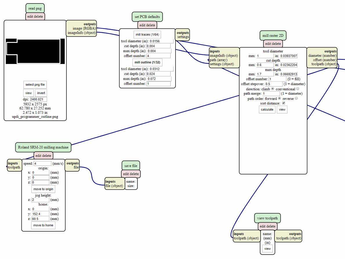
After settings are done, press calculate. To see toolpath press view under View toolpaths.
Milling
We started milling same time with Achille. We tried to create two boards from one piece of FR1 but it did not go as we planned.
We picked piece of FR1 that was already used. We meassured that it should have space for two.
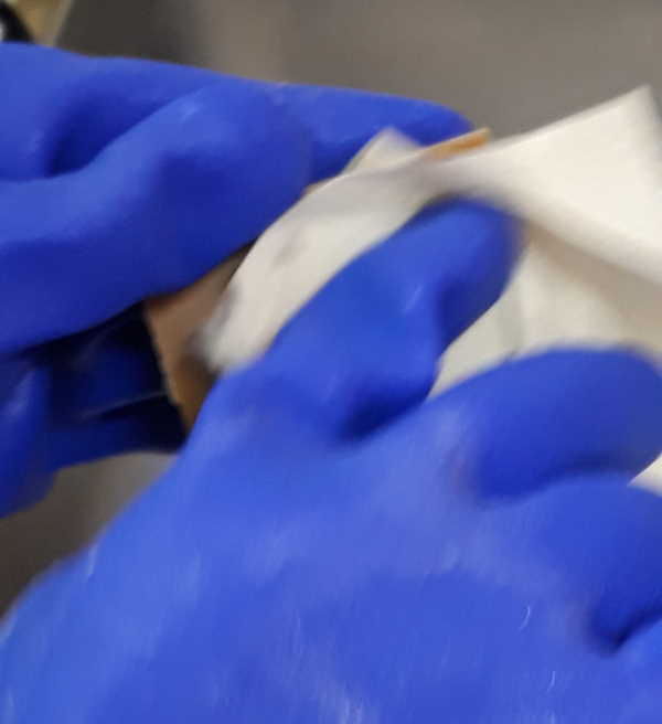
It had some residue of glue on backside so our first goal was to get rid off it. For this we used Isopropanol and piece of paper. This worked like a charm.
We used double sided tape to set it tight on the milling machine. It is important to avoid air bubbles under tape when attaching it into machine. Even small differences on height can make it hard to mill it evenly.
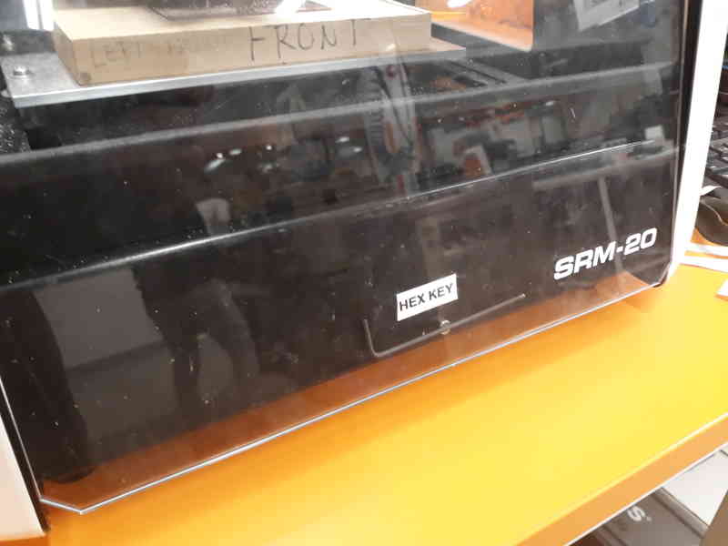
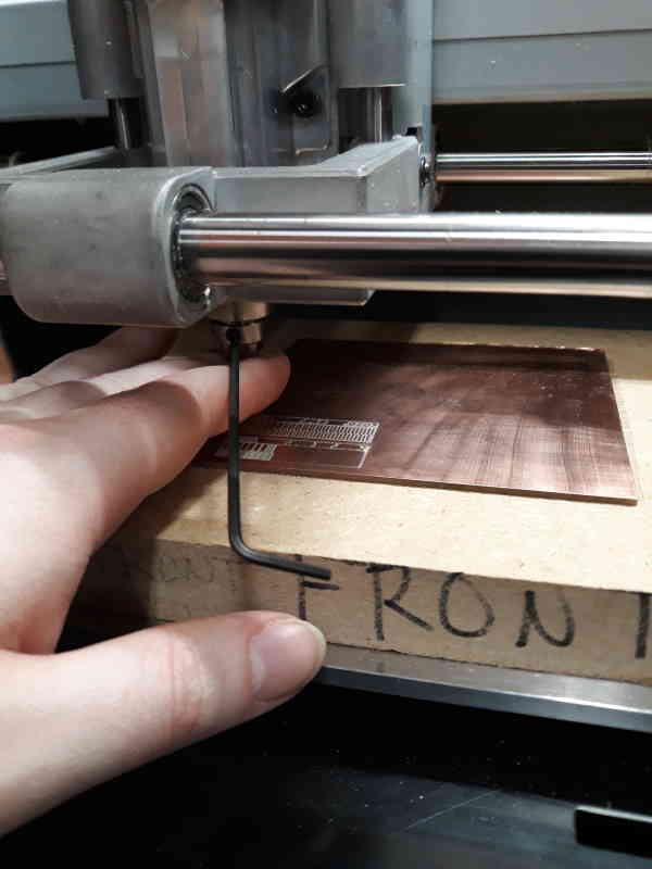
There is small magnet in our milling machine for hex key which is very useful. Before starting to mill we changed the end mill. For calibration and traces we used V-shape end mill. To change mill take a light hold of the end mill and loosen screw with a hex key. Screw can be only accessed from one side. Pull it down carefully till it is out of the socket.
When installing new one be careful that you tighten it lightly. It can be felt when it is tight enough because you would have to use much more force to continue tightening at this point. Last part before milling is to lower end mill as close to board as possible. For this first use software to adjust Z-axis as close of surface of board as you can see with eye. Then open screw again and put two of your fingers around end mill. Lower your fingers very slowly till you feel that end mill hits the surface of the board and tighten screw again. End mills break easily so extra caution and patience is advised.
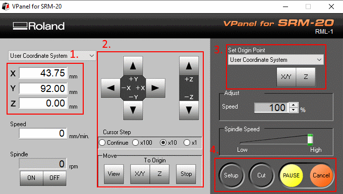
You control machine with VPanel for SRM-20 software.
- This shows where the end mill is currently compared to origin. 0 is origin.
- VPanel gives many ways to move end mill. At top there is buttons to move X, Y and Z manually. Changing Cursor step options makes it move with different speeds. x1 is 0.01mm, x10 is 0.10mm, x100 is 1mm and in continue mode one fast click is already 5mm. View moves platform closer and mill back. View and To origin Z is safe to check height of end mill.
- With this you set the origin. First move it to right position and press X/Y or Z.
- Cut opens another menu where you can select the file you want to mill.
When we we had set origins we started to try find right height. First we set Z 0.3mm and made that new origin. With this we checked that options were okay and it milled air. After this we gradually lowered it till we were satisfied with width.
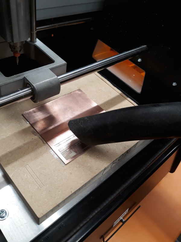
Board had some dust over it after running all three files. We used vacuum cleaner to clean it.
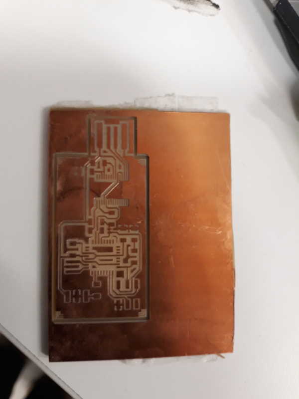
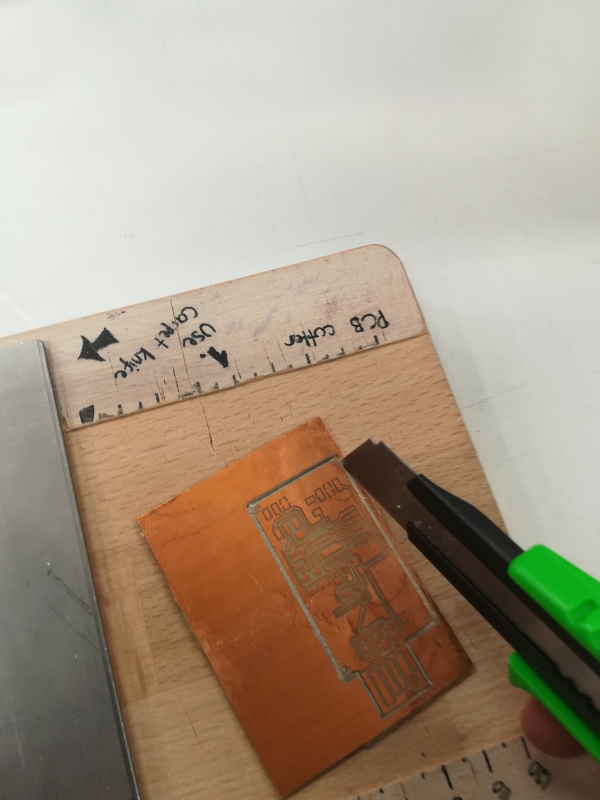
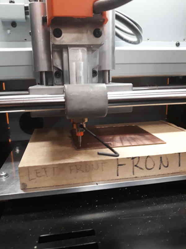
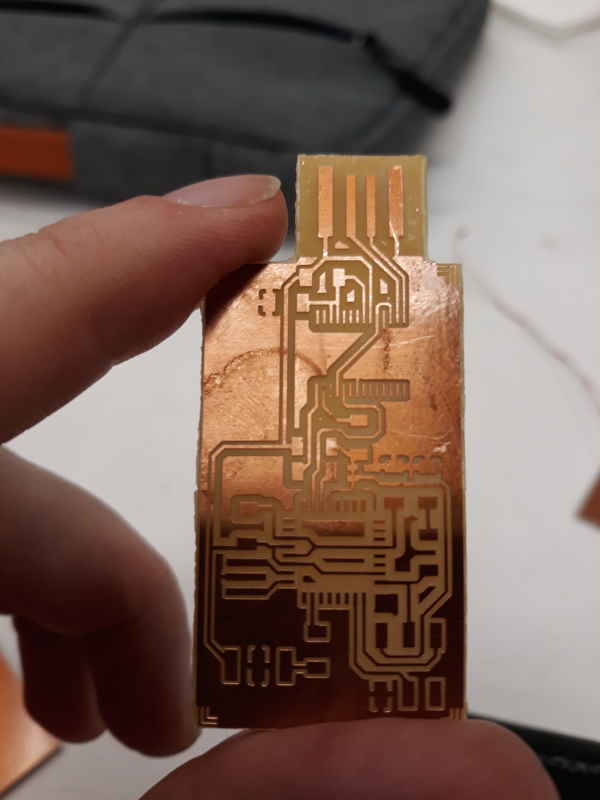
Here is the board after milling. For some reason it did not cut through so I had to cut it out with sharp knife.
Soldering
I dont have experience of soldering so this part took a lot of time.
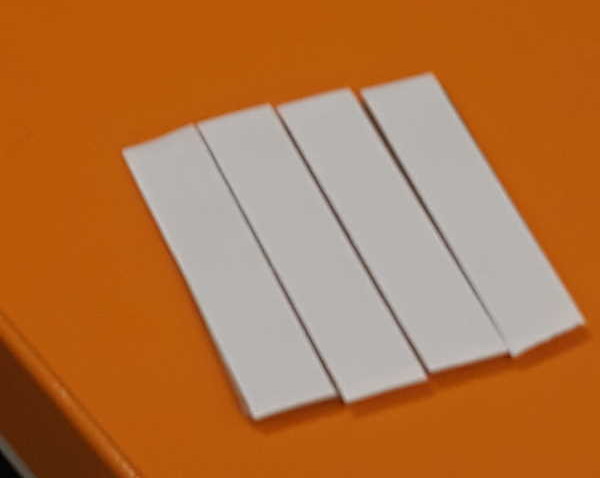
Peeled of copper at the end of board from outside of those four lines. Also cleaned copper side of the board with steel wool to get rid off top oxide layer.
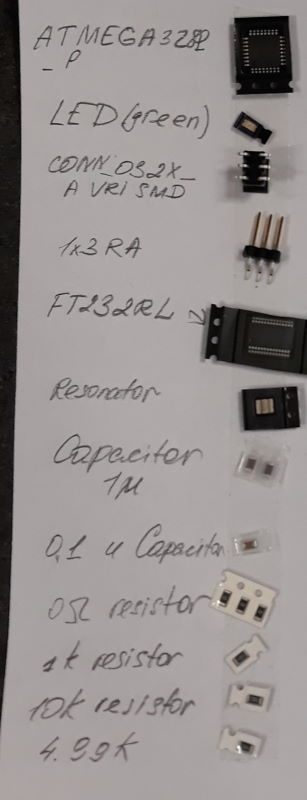
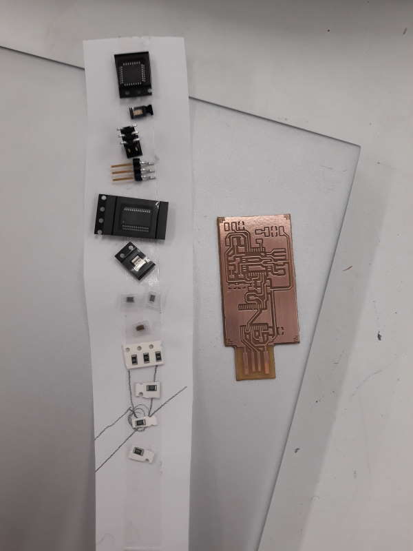
Here is the list of components. Some of these were challenging to solder.
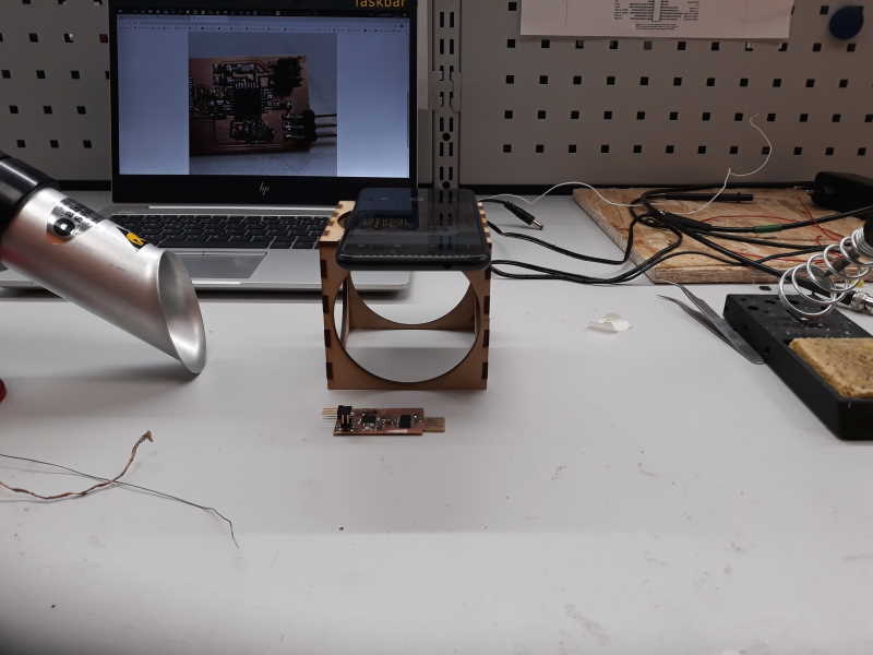
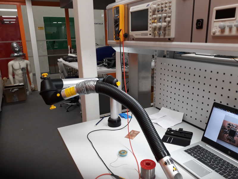
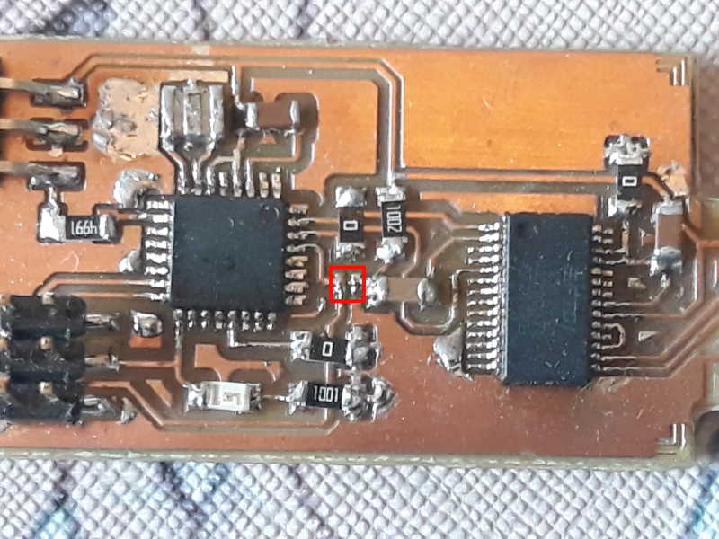
Here is the setup I used. We have only one microscope at lab so most of us were using phone's camera to see closer. Thanks for this belongs to our local instructor Antti. To see layout of components I used the image of the completed board.
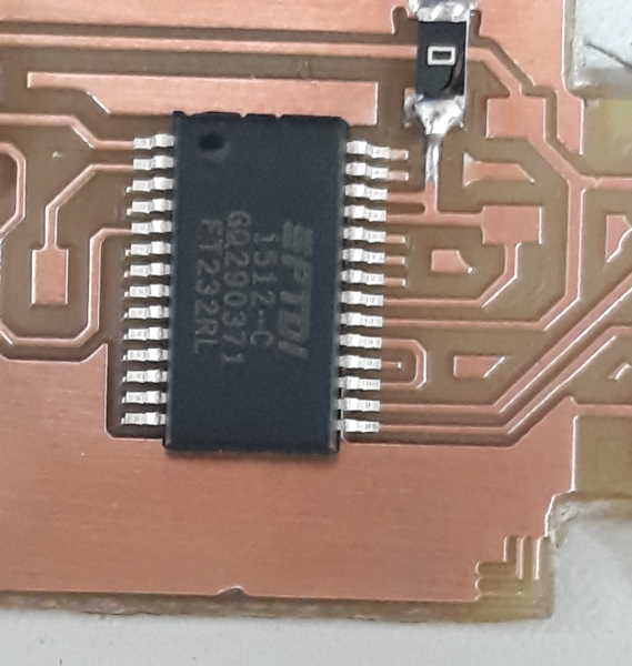
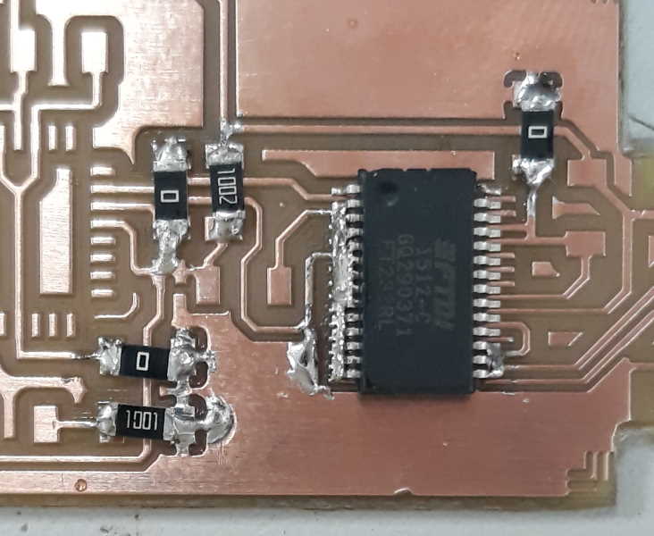
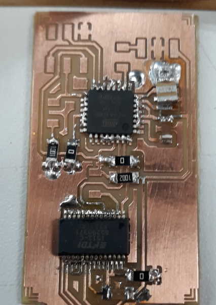
Here is couple pictures from the progress. I started with resistors because those were easier. After that I started struggling with the ATmega and FT232. At one point we had to detach FT232 with heat gun because it was so much offset. Although almost everything has been on this board at some point of progress.
Programming
After soldering I went through board with a multimeter to check for possible short circuits. There were couple mistakes, but with help of local instructor Antti and resoldering it started to work as intended. Since this board is too thin for a usb port by itself I put couple double sided tapes under usb end.
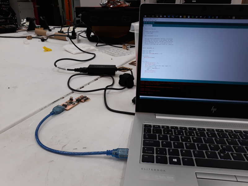
Next it was time program the microcontroller with a new firmware, USBtinyISP. To do this board was connected to a PC via usb. At this point it should pop up on the Device Manager under Ports.
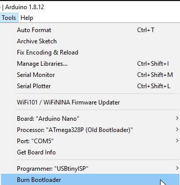
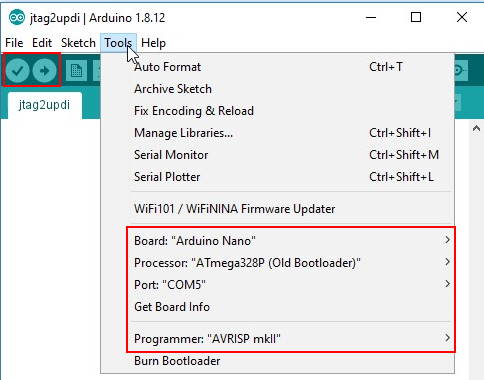
In the Arduino software (IDE) open the Tools-menu and set next values:
- Board: Arduino Nano
- Processor: ATmega328P (Old Bootloader)
- Port: COM5 (or which ever yours is attached)
- Programmer: USBtinyISP
- Press Burn Bootloader
If the program is ran successfully, the led should start blinking.
After successfully running the program, path from microcontroller to FTDI need to be cut. In my case there was no bridge to begin with so it had to be soldered.
In the next part it is time to upload jtag2updi on the PCB. For this first download and unpack the jtag2updi from github. It is also required to set few other things before we can continue.
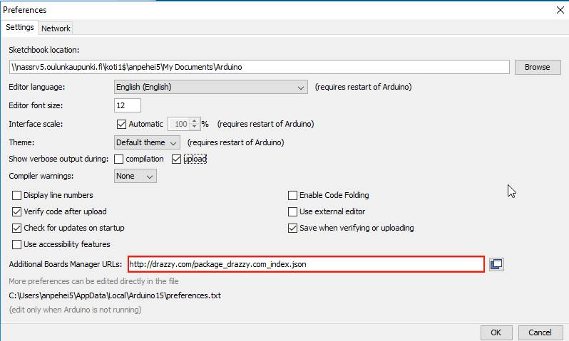
Open the Prefences from the File-menu. Set the following URL in the Additional Board Manager URL http://drazzy.com/package_drazzy.com_index.json.
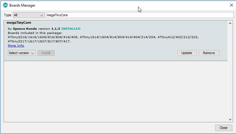
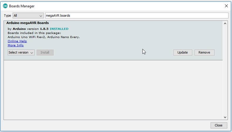
Next we need to download few board packages. Open Tools -> Board -> Board manager. Search and install following packages: megaTinyCore and megaAVR Boards.
Open the jtag2updi.ino. Set following settings on the Tools-menu:
- Board: Arduino Nano
- Processor: ATmega328P (Old Bootloader)
- Port: COM5 (or which ever yours is attached)
- Programmer: AVRISP mkll
- Press Verify and Upload
Now it is ready to use.
Testing
Testing if the programmer works with a Neil's echo.ini. Process is quite straightforward. First copy the code or write one yourself in Arduino.
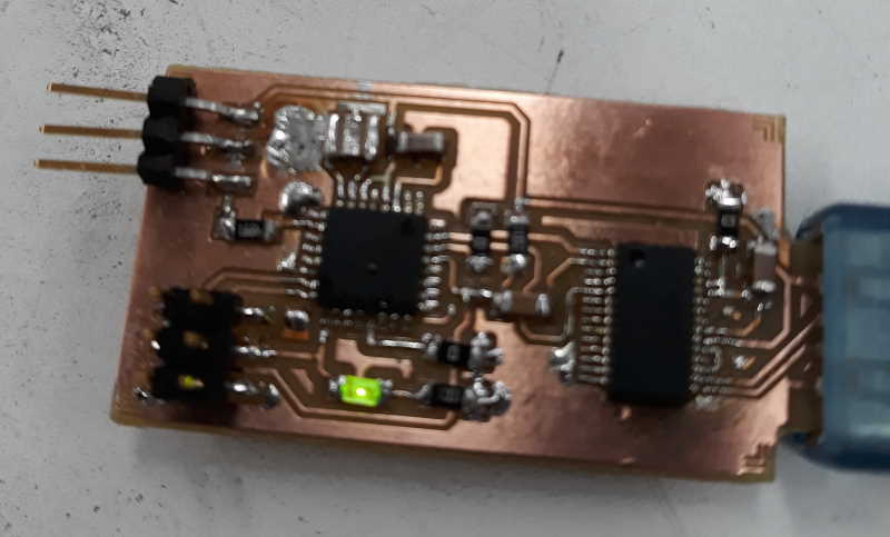
First connect programmer with USB to a PC. Then attach board you want to program to a programmer way you have designed.
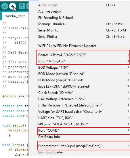
- Board: ATtiny412/...
- Chip: ATtiny412
- Port: COM5 (or which ever yours is attached)
- Programmer: jtag2updi
- Press Verify and Upload
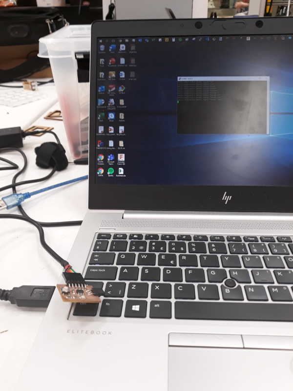
Connect echo board to a PC with FTDI-cable. As a note, remember that port is now different than when using the programmer.
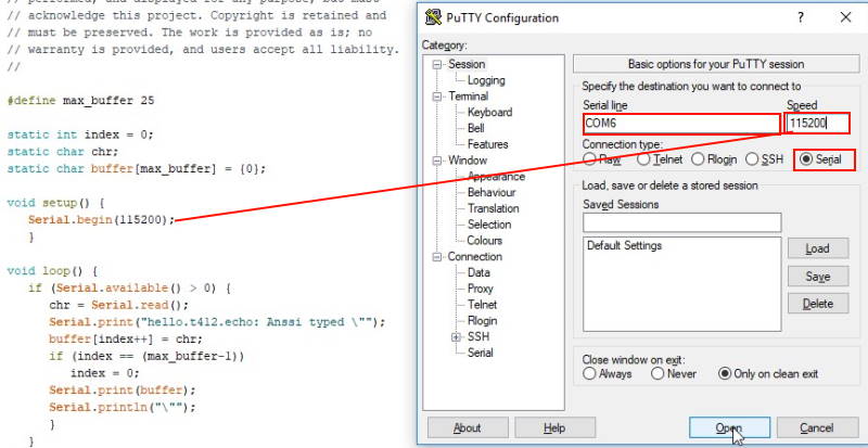
You can test code either in Arduino (Serial Monitor, shortcut ctrl+shift+M) or for example in PuTTY. PuTTY is free-to-use SSH and telnet client. For testing code you have to use Serial option. Check right Port from the Device Manager and put it on the Serial line. Set the chosen Baud rate (serial.begin) on the speed.
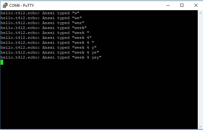
Here is the test result. Programmer works, yey!
Reflection
Soldering really took a long time for me to get into the zone. At the end it started going a lot better. I hope all that time spent on soldering pays off on upcoming weeks. On the other hand I am really comfortable with milling. Debugging the PCB was the most challenging (and frustrating) part this week. At the moment it stops when trying to burn bootloader on it. I also forgot to take pictures from every part of process this week. I find it easier to take screenshots of every step compared to photos with camera. Once again something to improve in upcoming weeks.