Week 6: electronics design
Group assignment
Worked with Achille, Hannu, and Jari in group assignment this week. Our assignment was to use test equipment from the lab to observe the operation of microcontroller circuit board. We used the oscilloscope to read characters which are sent to the ATTINY.
Whole documentation of our group can be found from Achille's page.
Individual assignment
individual project: redraw an echo hello-world board, add (at least) a button and LED (with current-limiting resistor) check the design rules, make it, and test it extra credit: simulate its operation
Eagle
I used Eagle to design my PCB. First I downloaded fab-library from github. We also downloaded SparkFun just in case.

It is easier to access libraries if they are unpacked to different than the default folder. I created folder straight under C that it is faster to access it. You can also set custom folders for other things such as projects.

Every library is not on use by default. To activate library press small dot next to the name of library. Black means it is not activated and green when it is.


We did not find part for ATTINY412 from fab-library. Because of this we started to search one from internet. We found one from SnapEDA. This one did not have a symbol so we created one.

Next we set pin layout and generate part.


After generating part it is time to download symbol and footprint. There is multiple file formats and for this case Eagle was right one.

First parts need to be put on the schematic. Parts can be added by pressing Add part -button from ribbon on the left. First part added was FTDI SMD HEADER.
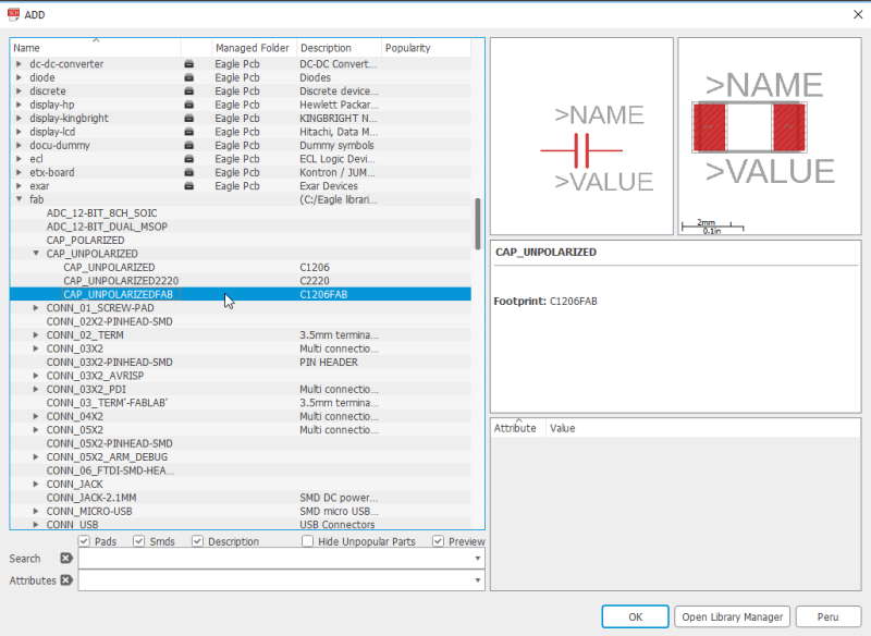
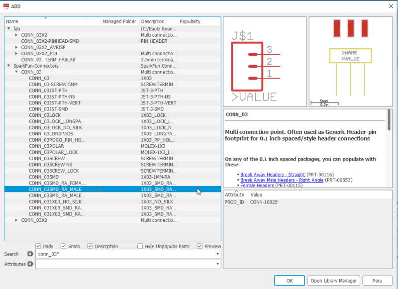


Next we added 4 new parts.

After adding parts they need to be connected with Net. Since board requires more than one VCC (Voltage Common Collector) and GND (Ground) it is faster to use copy -tool instead of adding new part. Copy can be accessed from ribbon on the left. After selecting tool it is required to press a part that needs to be copied and move it in to the wished position.
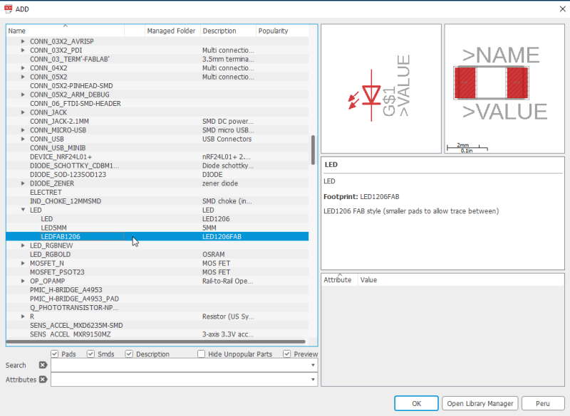

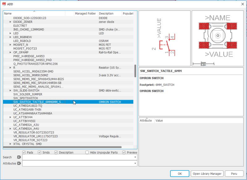
Next added LED, resistor and switch button.

Final schematic with all of the parts. Now it was time to generate board. This can be done by clicking pressing "Generate/switch to board" -button which can be found from menu above schematic.

This is the board side of the Eagle. After inspecting the board we noticed that we had wrong version of ATTINY412 because pins were so tight compared to Neil's picture.
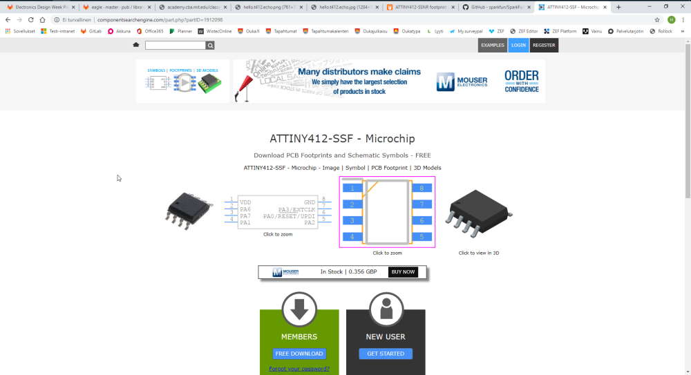
Local instructor Antti found right version from another service. This service is called Componentsearchengine.

After changing ATTINY412 most of the nets had to be rerouted. Also moved parts a little bit to make it faster to read.

I moved parts in to position which looked nice. After this I selected Route Airwire -tool and started to connect parts.

Next created rectangle over the design and wrote GND to Name text field.


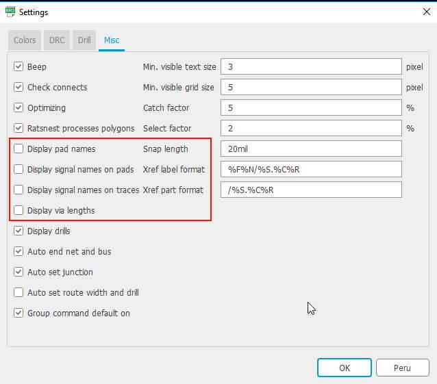
We changed clearance and supply settings from DRC-menu. All of the clearance were set to a 16mil and supply to 16mil aswell. Text on the airwire can be taken off by opening settings from the Options -drop down menu at the top of the Eagle window.

We created a line next to the edge of the board. This line was created on milling layer which is layer 46. Line width can be set above the board. For this it was set to 40.
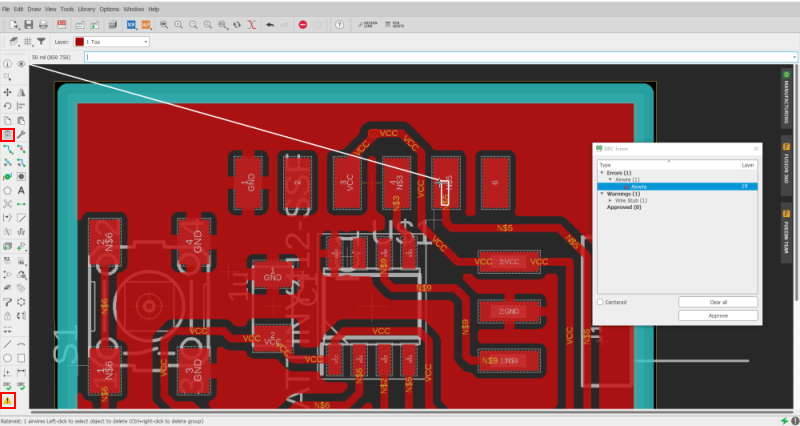
I had few extra paths of airwire in my design. These were created by accident while routing. I used Delete -tool to these.
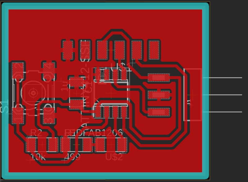
Here is the final board with GND copper pour on.

File for traces created with mods.

File for outlines created with mods.
Milling and soldering
I used Roland SRM-20 to mill.
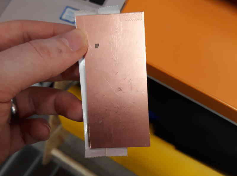
First I checked through used plates. I found one which had few markings but meassured that mine would fit inside of then. Again started by adding double sided tape on the other side.
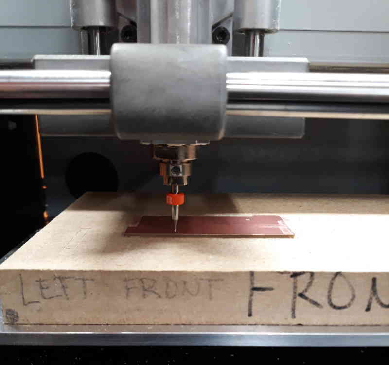
Traces were made with 0.2-0.5mm V-shape endmill.
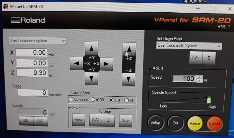

Set X/Y origin as close as possible to edge of board. After lowering endmill with my fingers to face of the board I set Z origin a little bit higher to check that everything is set correctly and lowered it gradually to find the correct milling depth that corresponds the tool width used in mods.

Here are traces. For outline we use different endmill so I changed it.

Milling outline.

It was time to collect all the components and put the board together.

It is ready to be programmed.
Programming
I had Arduino and addons ready for this task. First I programmed the board with the programmer we created on week 4. On week 4 I used same method as below to test if the programmer was working and This time tested if this board works. Workflow is exactly same on as was on that week.

First connect programmer with USB to a PC. Then attach board you want to program to a programmer way you have designed.

- Board: ATtiny412/...
- Chip: ATtiny412
- Port: COM5 (or which ever yours is attached)
- Programmer: jtag2updi
- Press Verify and Upload

Connect echo board to a PC with FTDI-cable. As a note, remember that port is now different than when using the programmer.

You can test code either in Arduino (Serial Monitor, shortcut ctrl+shift+M) or for example in PuTTY. PuTTY is free-to-use SSH and telnet client. For testing code you have to use Serial option. Check right Port from the Device Manager and put it on the Serial line. Set the chosen Baud rate (serial.begin) on the speed.
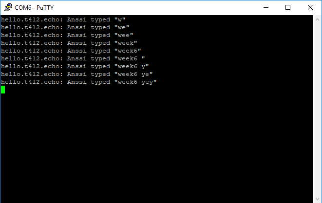
Here is the test result. New board works, yey!
Short video clip showcasing the program.
Files
week6.brdweek6.sch
week6_outlines.png
week6_outlines.png.rml
week6_traces.png
week6_traces.png.rml
Reflection
Soldering this week was less painful than it was on the week 4. Had only few small issues with it. Otherwise this week was fine and had more time to learn on this week compared to week 4.