Week 14: networking and communications
Individual assignment:
design, build, and connect wired or wireless node(s)
with network or bus addresses
group assignment:
send a message between two projects
Group assignment
Worked with Achille, Hannu, and Jari in group assignment this week.
Node-RED
We were discussing what we could do for the group assignment on this week when Jari suggested ESP8266s. Idea was to use multiple ESP8266s and send a message to specific ESP8266 by using Node-RED. Jari has already build a setup for the Node-RED on his Raspberry Pi. Communication between the Node-RED and ESP8266s is achieved by using MQTT communication protocol.
Jari has excellent tutorial on how to build the Node-RED setup on his Networking and communications page.
First we had to set up nodes. Jari had one ESP8266 with him already and we found one more from the lab. More would have made the result look more cool, but would not have made this task more difficult. Each of the ESP8266 requires separate Arduino code and a node in Node-RED.
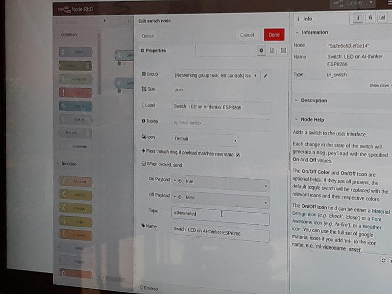
Making the nodes inside the Node-RED. Topic of the node is required when creating the code for the nodes in Arduino IDE.
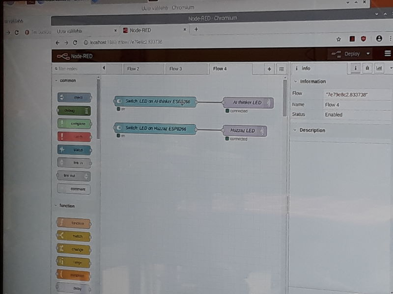
Here are the two nodes which we used.
Next we set the required information for each of the nodes in Arduino IDE. Files for the nodes can be found from end of this page.
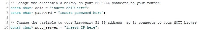
Set the SSID and password for it which is used for the communication. Also check the Raspberry Pi's IP address and add it.

Add the port of the led.

Next check topic of the node from Node-RED. In our case node1 is "aithinker/led" and node2 is "huzzaz/led".
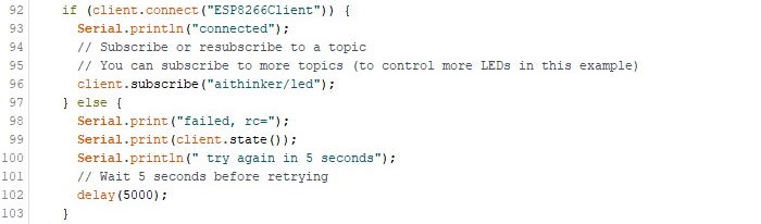
Add the topic of the nodes here as well. Rest of the code can be left as it is unless use case required different kind of prints etc.
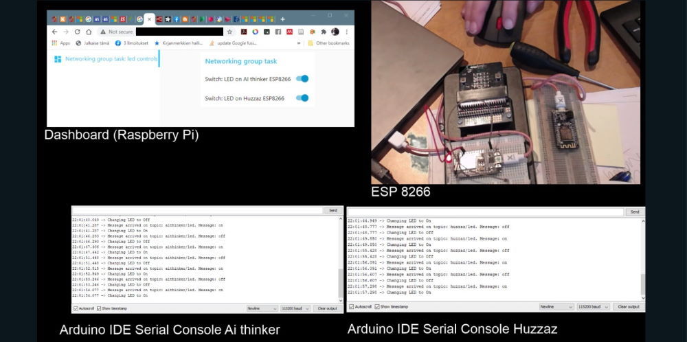
Here is the setup. We are using external led on node1 and onboard led on node2.
Project in action.
This was interesting assignment because this was first time for most of us using the ESP8266 and the Node-RED. We had some issues when working together at university because ESP8266s were not able to communicate with Raspberry Pi while using university's open WLAN or hotspot from phone. Jari was able to use it at his home though.
Adafruit IO
We made some changes for our group project after we received feedback from instructor. Node-RED caused a lot of issues while we were working together at university so Jari decided to change it to Adafruit IO. The plan was to use Adafruit IO to control leds. By using Adafruit IO we can leave out the Raspberry Pi and most of the problems were solved straight away.
Information about how to set up Adafruit IO and ESP8266 similarly as us, check following guide:
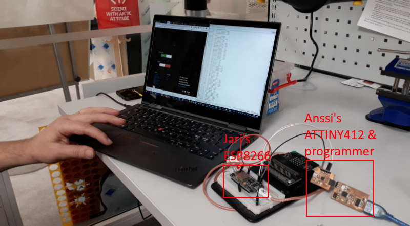
Here is the setup we used. It contained Jari's ESP8266 and Anssi's week 4 (for programming) and week 6 boards. We had external led which was connected to the ESP8266 and the ATTINY412 had onboard led.
Program for the ESP8266 is mostly from the guide linked previously with small tuning. For ATTINY412 we modified slightly the program Anssi used for this week's individual assignment. Both codes and the config.h can be found from the end of this page.
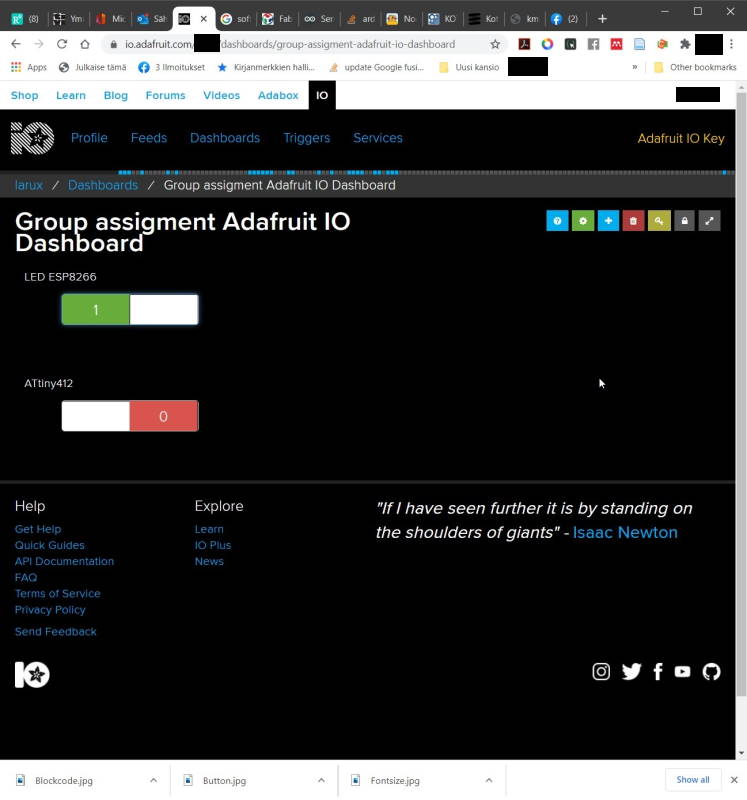

Here are the switches for leds on Adafruit IO and the output on the serial monitor.
Project in action.
We had a few small issues when combining the project at the lab such as couple typos and errors in the code, but nothing compared to struggle with Node-RED. Jari had already set up the Adafruit IO so that saved time as well.
Individual assignment
Our lab is currently closed due to covid-19. Because of this I will try to use my board from week 6 and Arduino UNO to learn the basics. Went through previous years to see what have they done on this week and to get ideas what to do myself with the limited resources at the moment.
I have a led and a button on my board and there's one led to use on Arduino UNO. With these I decided first test Jari Uusitalo's design to control both of the boards. First I had to check what pins are TxD (transmit data), RxD (receive data) and led. I used pins 0 and 1 on the Arduino UNO R3 and L-led is 13 which I had to check from the internet. For second board I checked from Eagle schematic since I didn't remember them. Learnt from my mistake on week 8 that I cannot use same pin-numbers as Eagle. By using the schematic and SpenceKonde's github I knew which pins to use in Arduino IDE. In this case RX is 3, TX is 2 and led is 1.


First I quickly tested that led works as intended on UNO by changing digitalWrite from HIGH to LOW. On HIGH it should be active and off with LOW.
Next I checked Jari's code and to learn what it does I wrote it instead of just copy-pasting. I had issues to get it to work because of typo. More about this a little bit later.
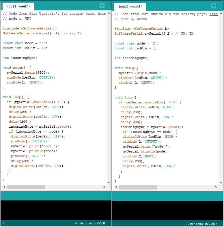
So this is the Jari's code with modification for my case.
#include <SoftwareSerial.h>
SoftwareSerial mySerial(3,2); // RX, TX
Including SoftwareSerial library and setting up pins for RX and TX.
const char node = '2';
This is to set up network addresses for the nodes. With this it is possible to control specific a device instead of all of them. In this case it's 2. When using char it is important to use '' instead of "" because it wont work correctly. In C double quotes are for string and single quotes for character. Char can be used either by using single quotes for a single letter, number, symbol or by using a number from 0 to 255 without quotes. With a use of ASCII Table it is easy to encode it.
In this part I accidently used "" instead of ''. Because of this incomingByte and node didn't match. Because of this both leds blinked, but did not print number of node and failed to blink again. First I though problem was due fact I used only UNO and one board, but tested it also with Jari's RX,TX,VCC and GND board. We started to understand the issue when we printed incomingByte and saw the data was in around 50's instead of in single digit numbers. In the end Jari noticed that I had used wrong quotes, but this was great experience of problem solving with code and was more useful this way.
if (mySerial.available() > 0) {
Serial.available() is used to get bytes which are available from the serial port. Purpose of this If-sentence is to execute next part after data has arrived.
incomingByte = mySerial.read();
if (incomingByte == node) {
This one is last a more specific part with Serial in this one. First sets up value from the Serial to a int incomingByte. This can be done with Serial.read(). Next checking which device is a match with the number user wrote in the terminal.
Just short video to show the code above works in practice.
Files
Node1_week14.inoNode2_week14.ino
Node1_week14_group_node-red.ino
Node2_week14_group_node-red.ino
config.h
Node1_week14_group_adafruit.ino
Node2_week14_group_adafruit.ino