Week 7- Computer Controlled Machine

Overview

For this week we have two assignments:

  1. Group assignment
  2. Test runout, alignment, speeds, feeds, and toolpaths for our machine

  3. Individual assignment
  4. Make (design+mill+assemble) something big

My Assignment Steps:

Step (1):Get the idea.

Step (2):The design process.

Step (3):The Milling and assembly.


The Process

Get the idea !

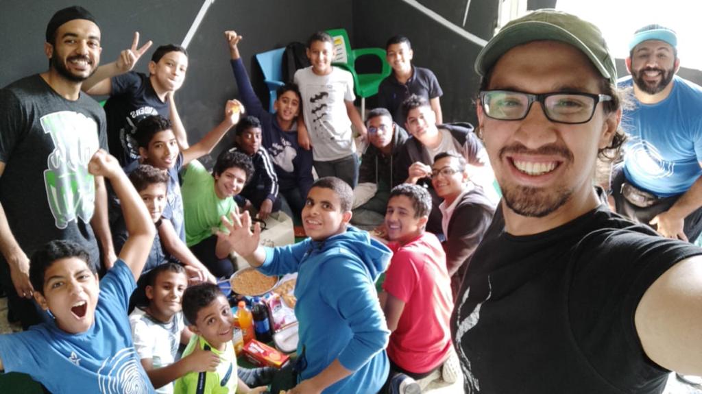
I volunteer as a kid coach in Ihyaa academy in which I help kids explore the field of media production especially the filmmaking and designing process.

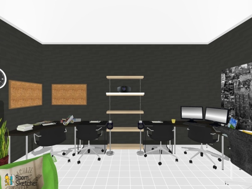
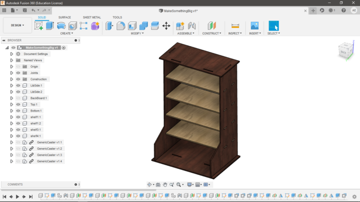
Revers studio is the name my kids choose for our team and somehow we started to build an actual small studio within the academy for them. So as you can see in the picture to the right we have number of shelves organized together to be used as a storage unit. Therfore, my idea is to create a double-edge shelves/whiteboard in order to make a good use of the small area we have.
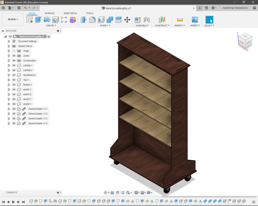
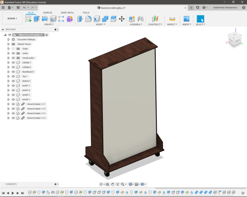
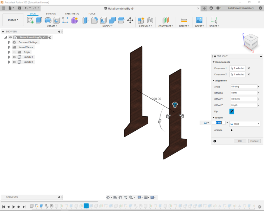
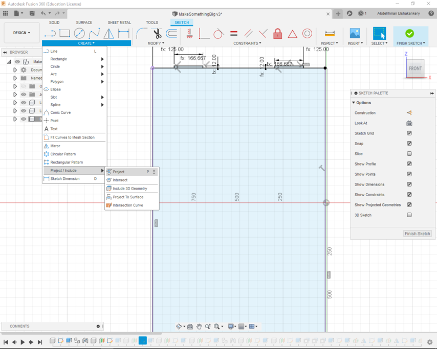
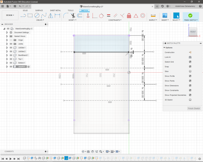
Responsive image
  • My super team.
  • Responsive image
  • The deisgn for Reverse studio.
  • Responsive image
  • The front of the double edge as storage unit.
  • Responsive image
  • The back of the double edge as a WhiteBoard for brainstorming.

  • The design process

    Responsive image
  • Start by creating the side.
  • Responsive image
  • duplicate the component then use the joint feature -don't just move it- to give a space between them. this really important to be able to make the design parametric
  • Responsive image
  • use project in order to choose the exact line you want to draw on.
  • Responsive image
  • start creating the shelves
  • Responsive image
  • extrude the shelves but to only the back of the unit.
  • Responsive image
  • make a room for the joints.
  • Responsive image
  • creating the fingers from on side.
  • Responsive image
  • choose midconstruction plan and mirror the fingers to the other side.
  • Responsive image
  • choosee combine to make the slots.
  • Responsive image
  • add 4 wheels
  • Responsive image
  • The design parameters.
  • Responsive image
  • a final parametric design.

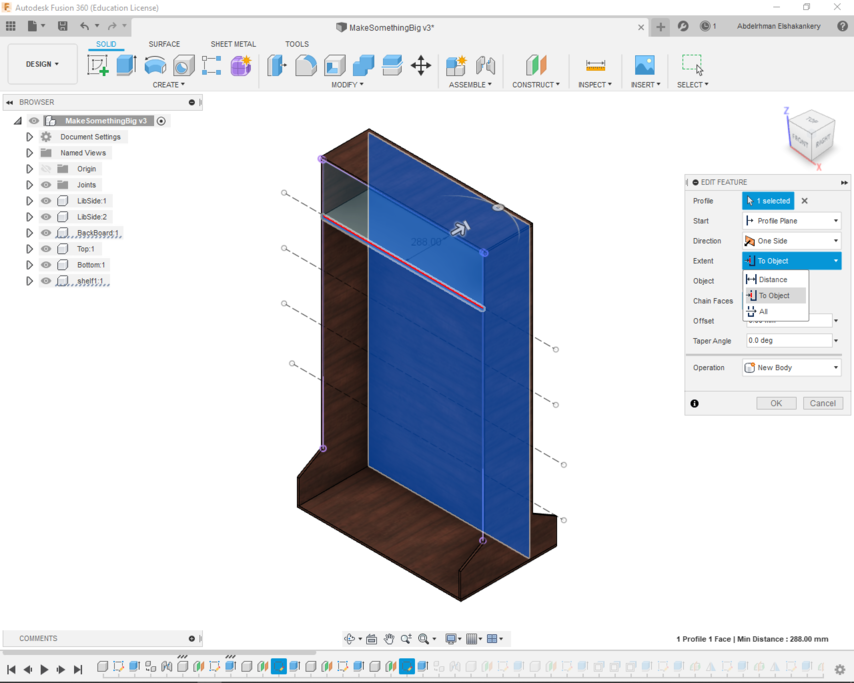
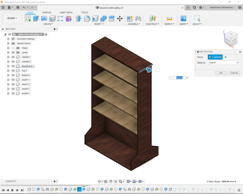
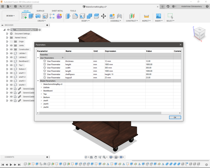
  • Edits due to Covid-19

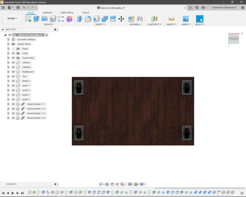
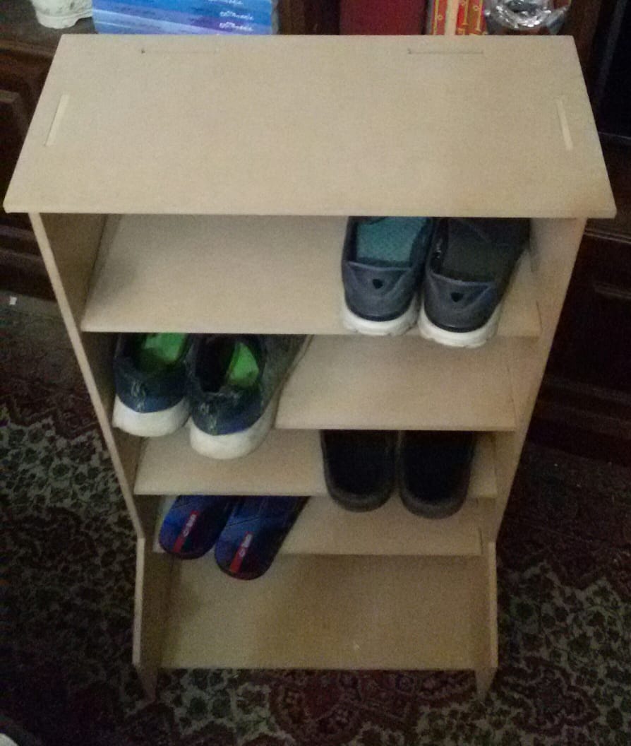
    Due to the circumstance of Covid-19 we weren't able to access the our Router machine till October and we have a limited size of wood sheet that my storage unit wouldn't fit, So I edit my design parameters and change my storage units to a Shoes cabinet

    Responsive image
  • Shoes Cabinet.

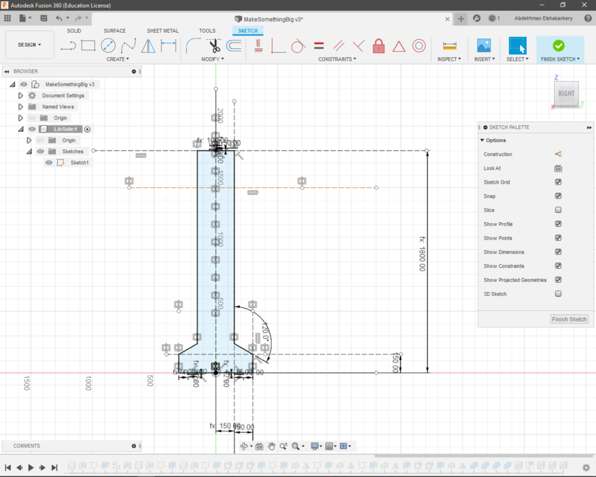
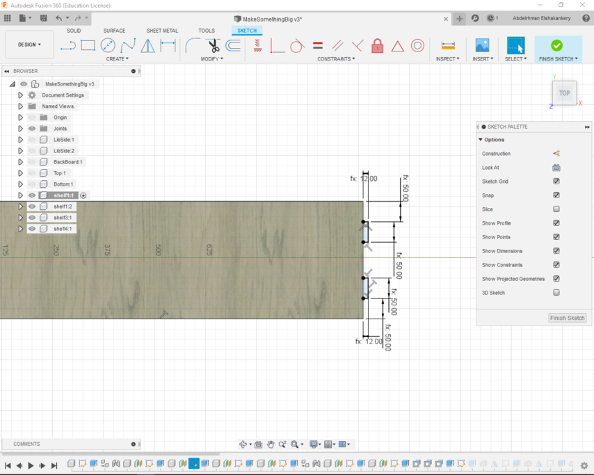
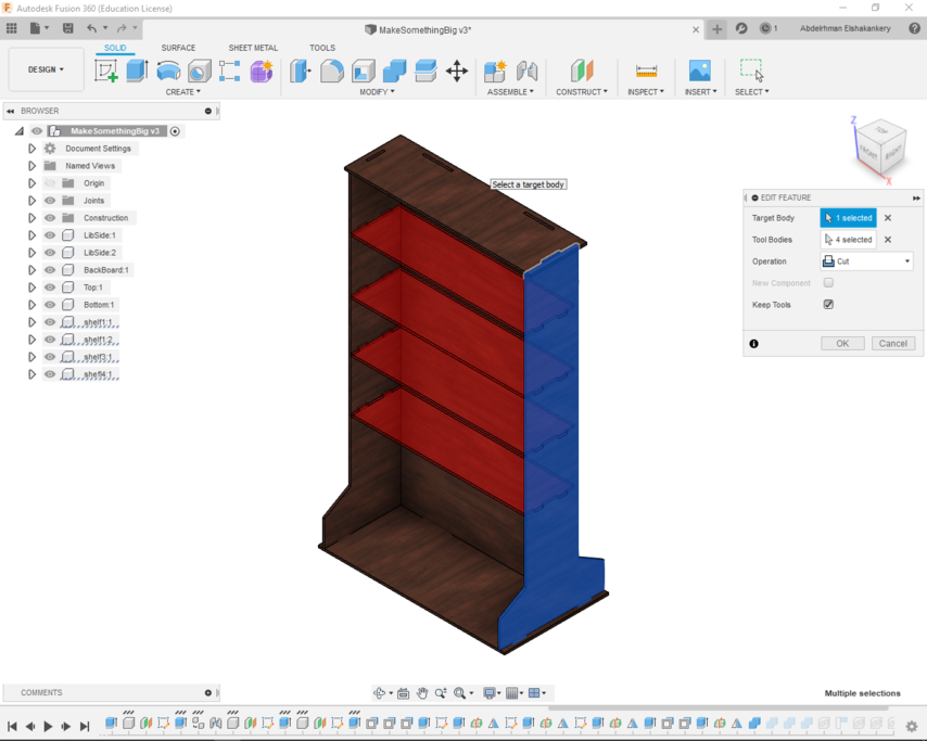
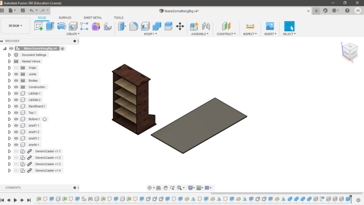
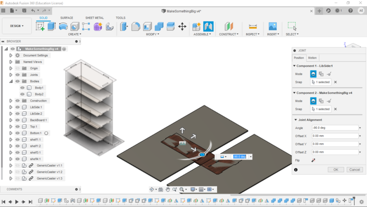
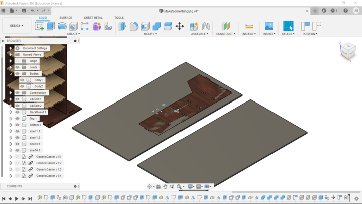
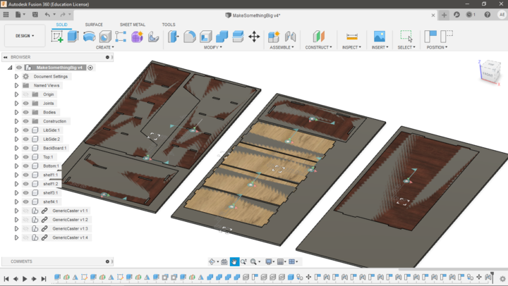
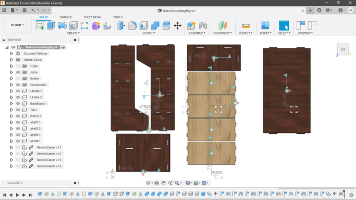
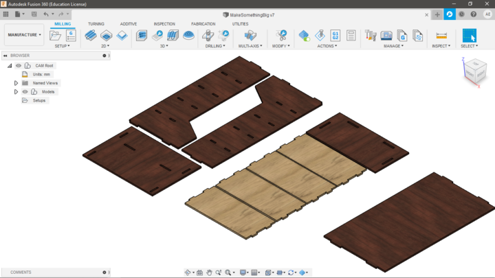
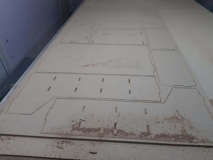
  • Flattening the design

    Start by laying all of my design part flat for preparing for CNC.

    Responsive image
  • create a box to simulate the stock I'm going to use.
  • Responsive image
  • Make a planner joint connection between the part and the box.
  • Responsive image
  • Move the part to fit inside the borders of the stock.
  • Responsive image
  • arrange all of the parts following the same steps.

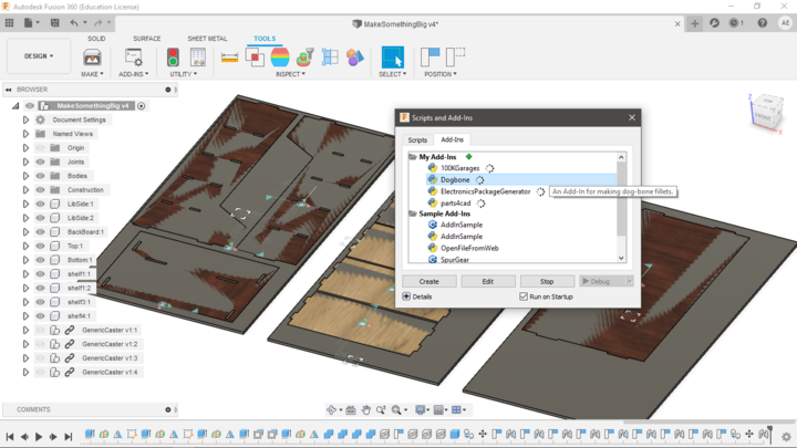
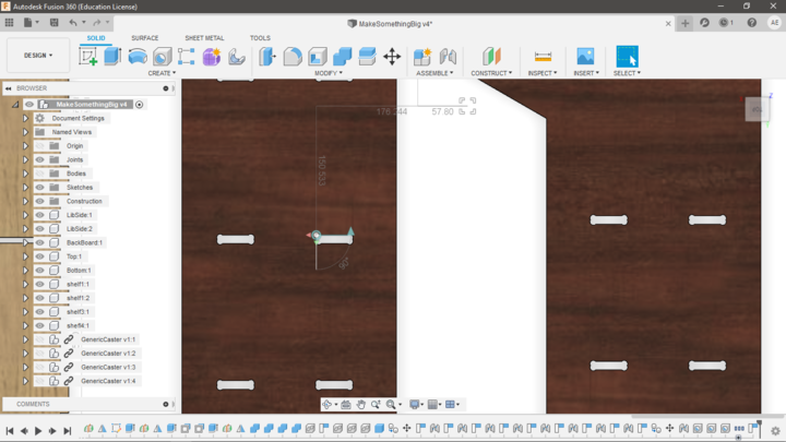
  • Creating the Dogebone fillets

    Due to the roundness of the drill bit it can't create the inside corner sharp edges. so we have to create a dog bone fillet to smooth the manufacture operation.
    instead of doing this manually I have downloade this online Dogbone Addin to automate the process

    Responsive image
  • Under Tools choose Add-Ins then run Dogbone Add-Ins I have installed .
  • Responsive image
  • choose the inner edges of the fillet with tool diameter = 6mm.
  • Responsive image
  • Now everything is ready for the manufacture process.

  • Machining Process

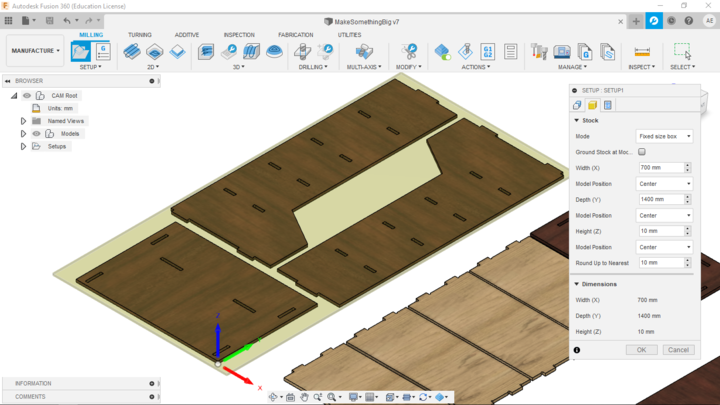
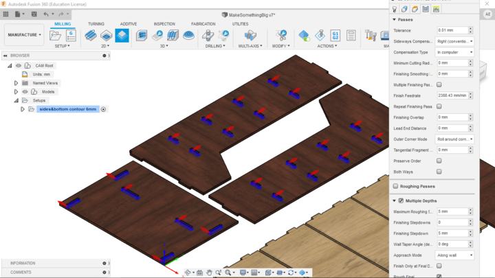
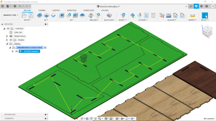
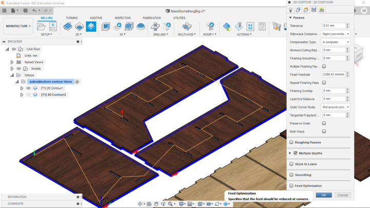
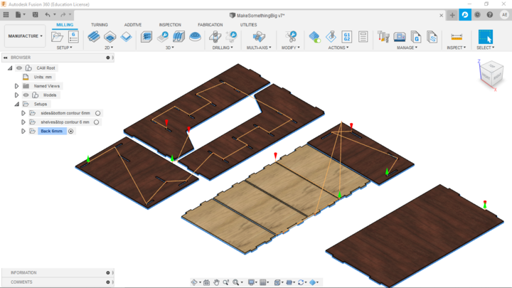
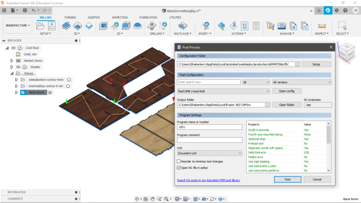
    1- CAM in Fusion 360

    Follwoing this simple and step-by-sgtep tutorial I was able to prepare my design for CNC manufacture.

    Responsive image
  • Change Fusion 360 workspace from Designing to Manufacturing
  • Responsive image
  • Create the first setup with the Origin points and the stock size.
  • Responsive image
  • Start by 2D contour the inner fillets of the first wood stock.
  • Responsive image
  • Then create a 2D contour around the parts outer edge.
  • Responsive image
  • The first stock is now ready for Milling.
  • Responsive image
  • Doing the same for the rest 2 wood stock
  • Responsive image
  • Post process the G-code.

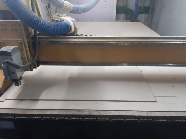
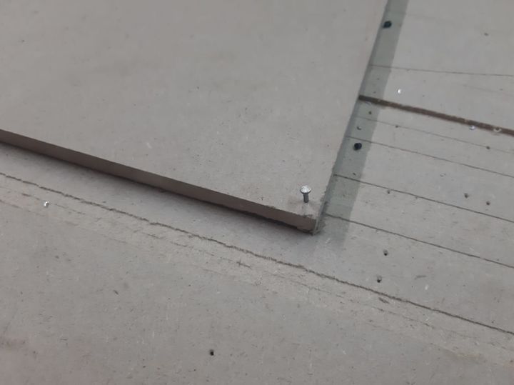
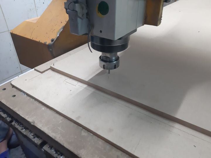
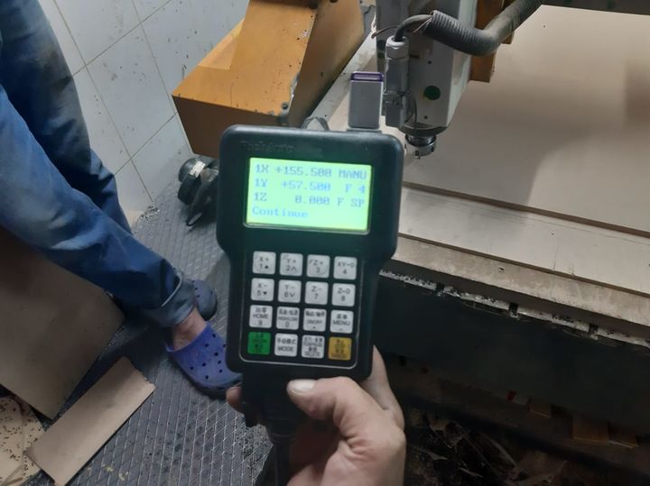
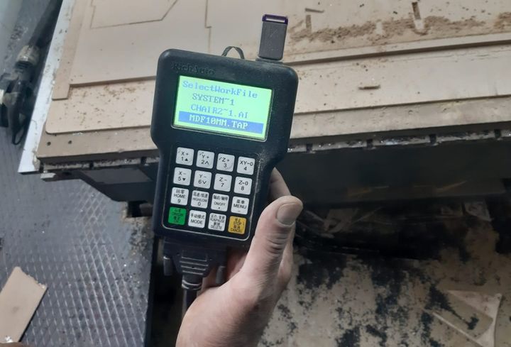
  • 2- Machining using HH-CR1325 cnc router

    Some of the machine specifications::-
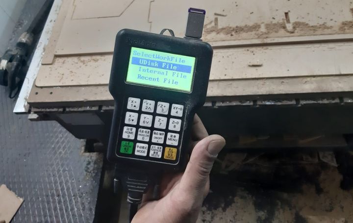
  • X/Y Axis Working Size: 1300mm*2500mm
  • Z-Axis working Size: 200mm
  • Working Table: Vacuum Adsorption /T-slot table /Aluminum working table.
  • Working Materials: Wood,MDF,Acrylic,stone, iron,alum,copper,bamboo,jade,etc.
  • Responsive image
  • Allign the MDF sheet on the workingArea.
  • Responsive image
  • Fixing the sheet using four nails in the four corners.
  • Responsive image
  • Using 4mm flatendmil tool and adjust the Z-level of the machine.
  • Responsive image
  • Set the Z-level, adjust the spindlespeed=15000rpm and the travlingspeed= 50m/s.
  • Responsive image
  • Choose flash memory to read the G-code file.
  • Responsive image
  • Choose the file you want the machine to start with.
  • making the first part.
  • Responsive image
  • Finishing all the parts.
  • Responsive image
  • The final ShoesCabinet.

  • Files:

    Find below the files that I made for this assignment. Please do not hesitate to download it!!

  • StorageUnits.f3z
  • ShoesCabinet.f3z
  • Top.dxf
  • Bottom.dxf
  • Back.dxf
  • shelf.dxf