Week 10. Molding and Casting
Molding & Casting
This week we learnt about molding and casting. A lot of contents have been covered in this week, including:
- the different types of molding
- different types of materials
- the process of molding and casting
- safety guidelines
- machining types
- Software needed
I’ll share some concise notes of what I learnt about the above-mentioned contents:)
Types of molding
1.Injection Molding
I’ve visited some injection molding factories in Shenzhen, where they have huge machines of making the metal mold, and then inject plastics into the mold to make the actual parts (some might be a part of a headset or power bank case etc.)
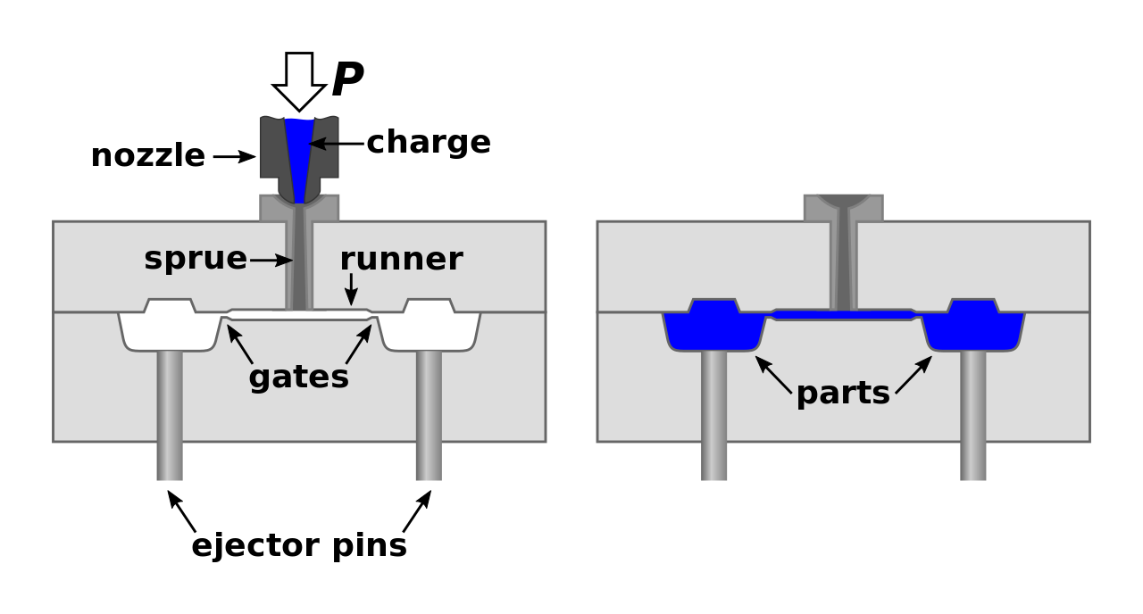
(a simplied diagram of the process of injection molding, credit: Wikipedia)
Injection Molding is adopted usually only when you go to a fairly large production, because the cost of making molds are not cheap.
2.Insert Molding
“Pre-moulded or machined components can be inserted into the cavity while the mould is open, allowing the material injected in the next cycle to form and solidify around them. This process is known as Insert moulding and allows single parts to contain multiple materials. This process is often used to create plastic parts with protruding metal screws, allowing them to be fastened and unfastened repeatedly.” – Wikipedia
3.Vacuum Molding
Vacuum molding is also known as vacuum forming, which is usually used in making packages. Back in 2014, my colleagues at Seeed DIYed a vacuum forming machine.

(Vacuum Forming Process, Credit: Wikipedia)
And Mayku team from Makerversity in London came up with this super cool Formbox vacuum forming machine that has a great success with their crowd-funding on Kickstarter. Mayku Formbox allows you to make artwork, food, home/office decoration projects easily.
4.Blow Molding
Blow Molding, quite self-explanatory is to inflate/blow materials into a mold. Blow molding is usually applied at making hollow objects, such as bottles/glasses etc.
“In general, there are three main types of blow molding: extrusion blow molding, injection blow molding, and injection stretch blow molding.” – Wikipedia

(Blow Molding Process, Credit: Wikipedia)
5. Rotational Molding
Rotational Molding requires you to rotate the mold which will make the softened material to disperse and stick to the walls of the mold. ” In order to maintain even thickness throughout the part, the mold continues to rotate at all times during the heating phase and to avoid sagging or deformation also during the cooling phase. ” - Wikipedia
(Rotational Molding Process, Credit: Wikipedia)
Types of materials
- Wax: Low-temperature wax, machineable wax etc.
- Rigid Foam
- Wood
- Alginate gel
- Rubber: Urethane Rubber, clear rubber etc.
- Polymers, epoxy
- Silicone
- Aluminum
- Clay
- Sand
- Glass
- Ceramic
- Food
- Many more…
Software Needed for Molding & Casting
- ShopBot VcarvePro
- Fusion 360
- Fab modules
This week’s group assignment is reviewing the safety data sheets for each of the molding and casting materials and then make & then compare test casts with each one.
And the individual assignment is designing a 3D mold based on the materials we have in stock and the tools we’ll use; mill it and use it to cast parts.
Group Assignment
The group assignment is to review the data sheets of each of the molding and casting materials we have in the lab.
For the molding material, we use wax, and the casting materials we have are PU resin 8017-A and 8017-B.
WAX
PU resin 8017-A and 8017-B
-
Safety Tips
-
Keep the material in locations with good ventilation.
-
Wear goggles and gloves when working with the materials, keep the materials from touching your skins especially eyes.
-
Usage
-
The ratio for mixing 8017-A and 8017-B is 1:1.
- Stir the mixed materials and pour it into the mold (need to work quickly, it will get solidified within 2~3 minutes.)
- Wait for about 30~60 minutes and you can get the cast.
Indivisual Assignment
Design No.1
The materials we’ll be using are:
- Urethane Mold Compound
- Rubber Mold Compound
(material images to be uploaded)
And the machine we’ll be using for milling the mold is
- Roland SRM-20
(machine image to be uploaded)
And I decided to make a stamp. The reason why I need a stamp is: we organize a lot of events at at Chaihuo x.factory. And I’d like to have a stamp that I can step our logo at the back of participants’ hands as a sign that they’ve sign in. In this way, we won’t bother them by asking them to sign in again when they go out & come back in. What’s more, the stamp can also be used to stamp your maker passport when you visit us at Chaihuo x.factory.
So the elements needed for the design should be:
- a logo of Chaihuo x.factory
- a round shape stamp
- dimension of the stamp shape: 2cmx3cmx0.5cm (width x length x thickness)
I decided to use Fusion 360 to make the design.

I need to turn the Chaihuo logo into the dxf. file.
Step 1 I used Gimp to convert the logo file into black-white png image.
(1) Open the Chaihuo Logo.png file with Gimp

(2) Color => Brightness-Contrast => Change the value of Contract to 127 => OK. This step will help sharpen the edges of the parts.

(3) Image => Mode => Indexed => choose “Use black and white (1-bit) palette” => Convert

(4) File => Export As => click to unfold “Select File Type (By Extension) => select “PNG image” => Export => Export.

Now I have a new png version of Chaihuo logo.
However, when I use Inkscape to open the png file, I noticed the flame part (which should be white in the png file) was missing.

So I tried other methods. And I noticed if I change the whole logo from colors to white, the exported dxf. file was blank. This means I can only use black image (white as the background).
I tried to use Mac’s built-in image edit function to change the image from colored jpg to black/white jpg file. And then use the previous steps at Gimp to convert it into png file. And it was recognized by Inkscape.
As the 3 versions of the Chaihuo x.factory logo below, only the last one works.

And when I finished the whole process, I tried an experiment. I can use Mac’s built-it image edit function to convert it from colored jpg file to black/white png file, which means you do not need to use GIMP in this step if you use MacOs (see the following steps).
(1) Double click to open the image file
(2) Tool => Adjust Color

(3) Move Point A to Point B (as shown in the image below), and the colored image will be turned into black/white image.

(4) File => Export, to export it as png file.

Step 2 I use Inkscape to convert the png file into dxf. file.
(1) Terminal => type “inkscape” => press “return” button to open inkscape on XQuartz
(2) File => Open => select the previously converted png file.
(3) Path => Trace Bitmap => Change the threshold value to 0.850 => click to select “Live Preview” => OK => close the “Trace Bitmap” window.

(4) File => Save As => select to save the file as “dxf. file”.
(5) When I open the Chaihuo Logo.dxf file, I got it as the paths in vector format.

I separate the letters/characters part from the flame+open source hardware part, and only use the image part for the next step.

Thank you for the detailed tutorial: Converting Png and Other Raster Files to Dxf Format.
Step 3 I use Fusion 360 to turn the dxf. Chaihuo logo into 3D file.
(1) Open Fusion 360 client
(2) Insert => Insert DXF => a window of “Insert DXF” will pop up => click “file” and select the Chaihuo Logo new.dxf file on my desktop => ??? However at this step, it showed the dxf. file is not recognizable. So I decided to try other methods.


(3) I tried exporting a SVG. file from the previous stl file on Inkscape, and repeat the previous two steps. And it worked!

(4) I selected the logo (all parts), and right click the mouse, choose “extrude” and see whether I can create a 3D file from this imported SVG file. It worked!

(5) So I canceled the previous step. Instead, I created the shape of the stamp in Fusion 360 through the following steps: Sketch => Ellipse

(6) Select the ellipse shape => right click => extrude => 5mm
(7) Select the local parts => right click => extrude => -3mm
(8) Export as Stl. file.
However, I came across two problems here. First of all, the Fusion 360 interface showed my free trial has expired and the icon “Make” is gray, there is no option of “export” or “save”. I clicked the “Make” icon, and with a few steps, I let Fusion 360 know I only use it for non-commercial projects. And then I am able to save and export.
And here comes the second problem: There is no option of “saving it as stl. file”. When expect “export”, there are 5 file format options, non of them stl.

And when I click “Make” icon, there is no trace of saving it as a stl. file either. And then I Googled for a solution. Great to see this article on Sketchfab. And I managed to export the 3D models into 3D files. The solution: File => 3D Print => UNcheck “Send to 3D Print Utility” => CHECK “Preview Mesh”, and then you can save it as a stl. file.
You can see two versions of my 3D design below.


I converted the files into GCode and used our 3D printer to print out the part. I want to see the 2nd version in solid object, so that I know how I need to improve it before actually milling it with the machine. And here is the outcome from the 3D printer. It looks fine. But, I neglect another part, I need to build a thin and a bigger outfit, so that when I make the cast part, there is an extra base of the stamp instead of a bare logo.
So I created the upgraded version of the 3D file. You can see the 3 different versions below. I am thinking about change the size and maybe make necklace or earrings from this :D
_
_
Now I have the 3D designed files ready to make molding and casting. Will go to SZOIl to us the machine & materials to finish this assignment. Can’t wait!!_
Software and Machine: Modela Player 4 & Roland SRM20
Today I came to SZOIL to continue working on my assignment about molding & casting with Aisling. We used the following software & tools:
-
Software: Modela Player 4: for setting the cutting path and generate rml. files of roughing & finishing for milling.
-
Roland SRM20: for milling the mold.
Since the Modela Player 4 doesn’t have a MacOs version for me to use. I used the one on Aisling’s laptop to set the milling path. However, we noticed that Modela Player 4 on hers did not have sufficient options when we were setting the end mill. So we switched to the Modela Player 4 on the Desktop computer, and use 3mm end mill for the cutting.
With the first setting, the preview cutting showed some parts are missing. We assume the reason is the mold is small and yet the end mill is too large to mill small parts. So we readjusted the mold and make it a bit larger, the preview showed OK. So I went on with it.
However, even with the 3mm end mill, some of the design parts were missing. What’s more, the design was too shallow for me to make the cast of the stamp. So I redesign my file, to make the cut traces deeper. Also, this time, I chose 2mm end mill to cut both the roughing and finishing. The initial intention was to use 3mm end mill for the roughing and 2mm for the finishing part. However, When Aisling tried it this way, it’s not easy to adjust the Z axis, so she suggested me using the 2mm for the whole process, both for roughing and finishing.
Here is the process of using the Modela Player 4:
-
Open the Modela Player 4 client on the computer
-
File => Open => select the STL file of my design => Open
-
Model (on the upper right corner) => check the dimension of X,Y,Z => change the dimension if necessary (Note: check the item “Keep XYZ ratio” before changing any value, or the design will be deformed.) => OK
I changed my dimension, because when I used the origional dimension, some small parts (especially the edge parts are missing). So I changed the dimension to: XYZ = 80mmx89.7mmx20.66mm. -
At the same interface, click “Origion” to set the origion of cutting.
The default origin is in the middle. I changed it to the left corner. -
Set => New Process => Roughing => Next => Next => Change the Tool value (In our case, we used “2mm Square”) => Next => Next => Next => Finish This will generate the tool path for the roughing part.
-
Set => New Process => Finishing => Next => Next => Change the Tool value (In our case, we used “2mm Square”) => Next => Next => Next (in this process, you can change the speed of XY or Z axis) => Finish
-
File => Preview cutting
Here you can see a preview of the cutting outcome -
File => Select Machine => Model Name: SRM-20 => Command Set: RML-1 => Printer Name: Roland SRM-20 => OK
-
File => Cut => It will pop up a window, check “Output to file”
In this way, it will generate the tool paths of roughing and finishing into two files respectively. Please make sure you save them at the file that you can find easily. I created a file named VS on the desktop, and save them there.
Now it’s time to use the Roland SRM client for the cutting:
1. Open the client of VPanel for SRM-20, which will be controlling the Roland CNC in making the mold.
-
Set the origin: Click the arrows to change the position, when it’s confirmed, click XY and Z to set the origin for XY axis and Z axis respectively.
-
Cut => select roughing first, when it’s dine, select finishing to continue.
After several attempts, I still couldn’t made a good milling part from the above-mentioned processes and settings. The other day it took me 7+ hours to cut out a mold, which was actually not in a very good quality.
I had a conclusion that my design has too many shape curves and the drill dip couldn’t go to very detailed angles. And it also took much more time in the process.
So I decided to make a simple design.
Design No.2
This time, I used Fusion360 to design a heart shape.
I followed this tutorial to draw a heart shape.
- Sketch => Spline => draw; to draw the first half of the shape.

-
Sketch => mirror => create the other half

-
Here I have the heart shape in sketch.

-
click the heart shape, right click to “extrude”, and also click the background circle to extrude.
-
Now I have a 3D version of the heart shape ready.
_
Software setting & machine operation
And then I used Modela Player 4 to create tool paths for milling. For the detailed steps, I’ve already listed above. Here I share some screenshots of the process.
- Open the file, please note even though when scroll your mouse and the shape seems to be lying flat, the orientation is not correct.

Do look at the upper right corner of the screen, and select the right top surface, and you can see the orientation changes.

- Choose origin

- New process - roughing

-
Drill dip diameter setting (I chose 2mm for both roughing and finishing)

-
New process - finishing

-
Tool paths created

-
Preview cutting

-
Output the files and I used Roland CNC -SRM20 for milling.
-
I choose 2mm drill dip, set the X,Y,Z axis and began cutting.
-
And here is the result.

Silicone mold
Now it’s time for making a mold!
I decided to make a silicone mold. I used the following materials:
- silicone 881#
- curing agent

According to the instruction on the material package, the ratio should of the above two materials should be: 100:2~2.5.
I prepared gloves, measuring cap, container, and a mixing rod.

After mixing the silicon 881# with the right ratio of the curing agent, I pull them onto the wax mold I made.

Now just be patient and wait for about 6 to 8 hours!
I noticed there are small bubbles when I first poured the silicone onto the mold, but after a while, the small bubbles began disappearing.
PU Resin
While I was waiting for the silicone mold to be ready, I was eager to see what my mold looks like. So I made another wax mold with the Roland CNC. And this time I used PU resin 8017-A and 8017-B.
Here is the new wax mold I made, with slightly larger dimensions.

And here are the PU resin 8017-A an 8017-B.

I got the mold, the PU resin 8017-A & 8017-B, measuring cups and containers ready.

Use measuring cups to get exactly the same volume of 8017-A and 8017-B, aka ratio 1:1.

After stirring a little bit, pour the mixed chemical into the mold. And here shows the mold in progress.

In less than 30 minutes, I got the PU resin mold here.

Note: Since the wax I used here was soft wax, when pouring the resin 8017-A&8017-B. into the mold, the heat generated in this process melted the edges a little bit. You can see from the above mold, the surface is not very smooth. What’s more, the thin layer on the top, which should be covered with resin, was not shaped properly, leading to a hollow mold, without a base. It seems soft wax is not suitable to be used with PU resion in this way.
File-A wax + PU resin 8017-A & 8017-B
Since our local instructor Yufei has also prepared some File-A wax for us. I decided to try it as well.
I used the same method on Modela Player 4 and Roland CNC SRM20. Since the File-A wax has a much smaller dimension, I changed the dimension of the mold I wanted to make as well.
The smallest tool diameter I can choose on Modela Player 4 is 1mm, so I chose this one. And I used the 0.8mm drill dip on the CNC.
It was actually quite fast. And here is the file-A wax mold.

I remembered in the previous steps, it was actually quite difficult to get the PU resin mold out from the wax mold. So this time, I smoothed some vaselin on the wax mold.

Mix 8017-A & 8017-B in ration 1:1, stir a little bit and pour it into the wax mold.

And the vaselin did help! I got the PU resin mold very easily!

After taking out the PU resin mold, I noticed the file-A wax mold remained the same without any damages. I pour silicon into this tiny mold as well. Now I have three different dimensions of silicon molds in the process of taking shapes. Will update when they are ‘born’ :D
Casting
I chose the following two materials for casting: polymer clay and ultralight clay. Since we used to have a lot of workshops for kids back in 2016, and we still have some of these materials in stock. It’s convenient for me to get access to these materials for casting.
polymer clay
“Polymer clay is a type or hardenable modeling clay based on the polymer polyvinyl chloride (PVC).” (Source: Wikipedia). It usually needs to be put into an oven to harden.

(Polymer clay)
The polymer clay was quite hard when I first got it out from the package. It requires me to knead the polymer clay for a few minutes to soften it. And then I put the soften clay into the mold I made previously for casting.

When the shape is fully formed, I got the heart-shape clay out. It requires to be put into the oven for about 15minutes at the temperature of 130°(Celcius) for curing.

ultra-light clay
Ultra-light clay is a new and environmental-friendly material, which can be left for curing by itself without extra procedures in a machine such as an oven.

(ultra-light clay)
As long as the ultra-light clay is sealed in the package, it remains soft. I took out a little bit of it, kneading it to squish out the air. And then put it into the mold for casting.

When it’s fully formed, wait for about 24 to 48 hours and it’s cured. You can see the result below.

Also, since my previous mold can be designed on a 2D software. And I should design a 3D mold that should be design on a 3D software and couldn’t be design on a 2D software. So I design a half sphere on Fusion360.

(screenshot of the sphere design on Fusion360)
And similarly, I used Modela Player 4 to create the tool path files for milling the mold.

(creating roughing)

(selecting tool diameter)

(rouhing preview)

(finishing preview)
 (molding simulation)