
TARS version 1.0
2D Modeling with InkScape
After this section I should rename TARS into Timber. Astronomical. Robotic-like. Stereopticon.
Firstly I was dead sure that TARS' chassis will be 3D printed. In the designing process I realized that it is unnecessary efforts and shapes are dangerously similar to bricks. This somehow pushed me to create case in InkScape and TabbedBoxMaker. It is a Python based application, which may be downloaded from GitHub. After extraction following files has to be copied into following folder:
\Inkscape\share\extensions: Boxmaker.inx, Schroffmaker.inx and Boxmaker.py.
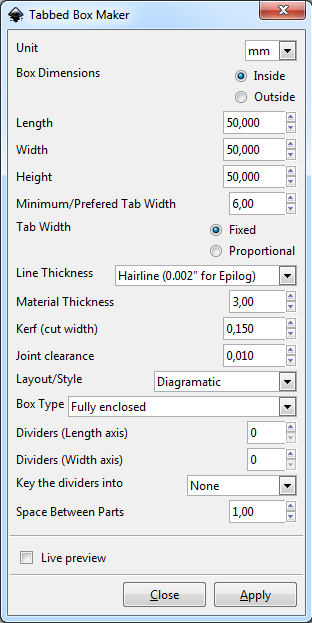
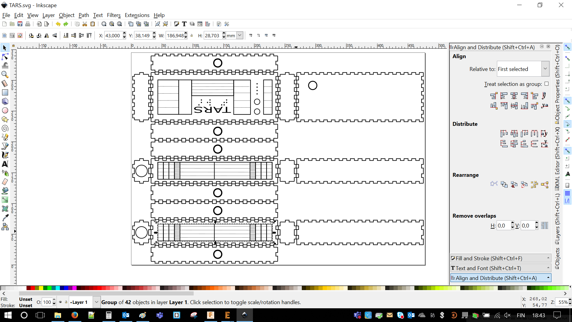
As I wasn't using it previously I feel it require a bit of explanation. Below there is a screen shot, which shows how to find this toolbox.
Side note: For laser cutting it's important to to set the line thickness to "Hairline (0.002 for Epilog)", Kerf (cut width) and Material thickness according to the used material (in my case 3 mm MDF). Other setting define dimensions and shape of the box.
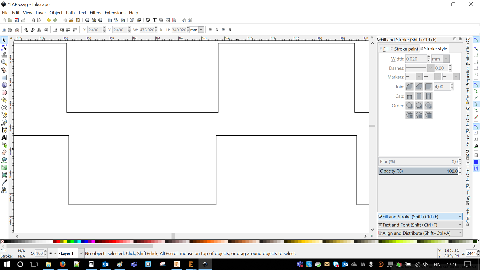
In general chassis designing was time consuming. Especially after I'm very much into straight lines and right angles. It means that I didn't accept any other angles and I had to correct everything from time to time. As I said I made a box using previously mentioned tool.
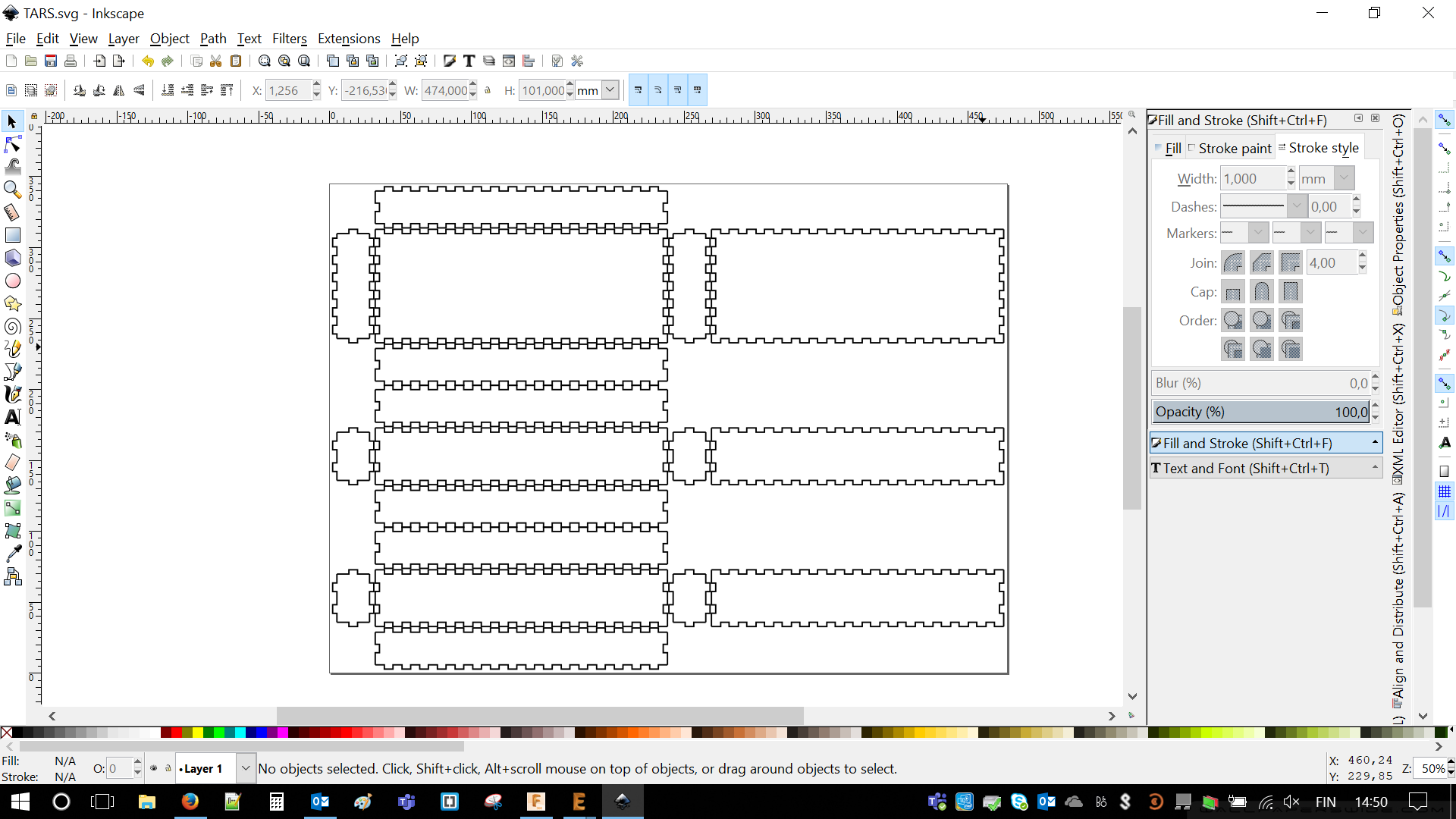
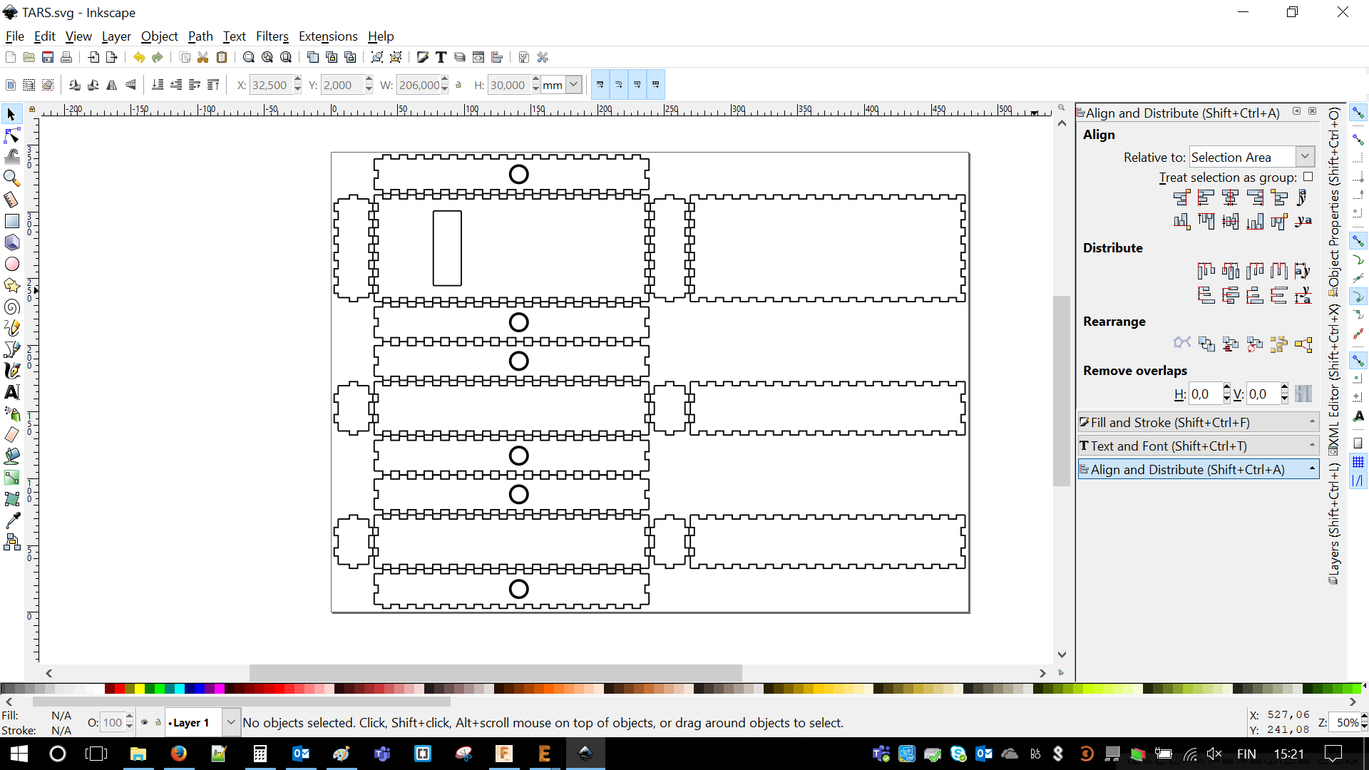
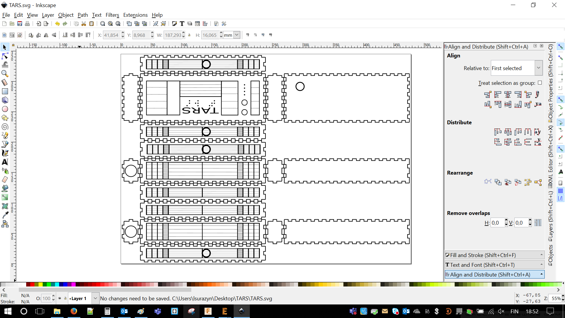
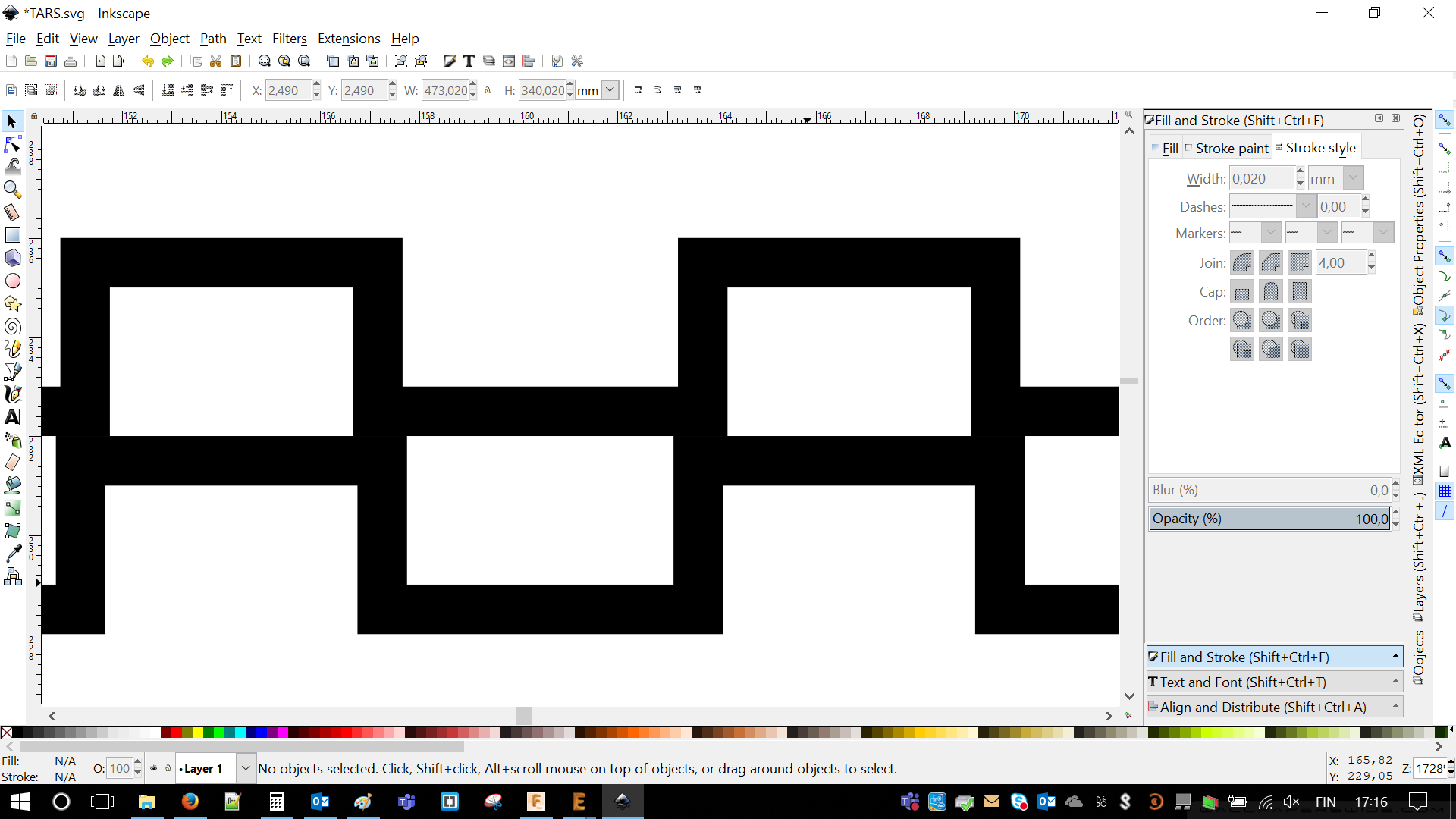
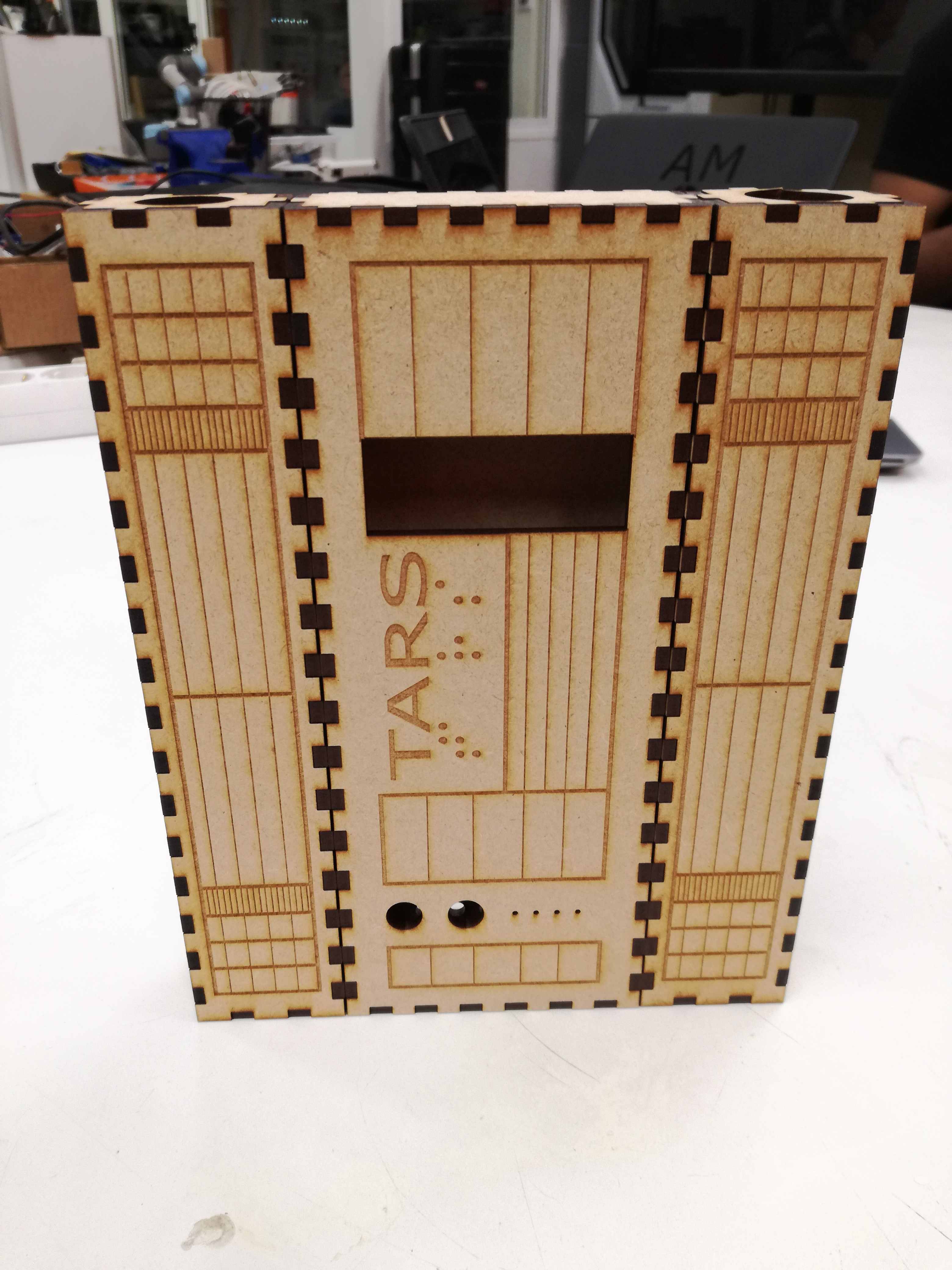
Then I started putting holes, which will be cut trough. There was a place for LCD screen and wiring for both Rainbow Generator and Dark Sky Map, those were placed on the sides. Just for my own sanity I changed width of all lines to see them properly.
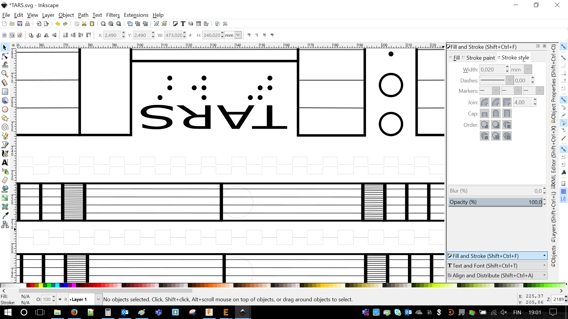
Then I started creating details, which will be engraved on the chassis. Peek onto TARS from the movie. Creating lines, aligning them. Another peek another lines. At this point I started to question if I really need that many details.
So I continued adding details. I was trying to make TARS looking as much similar as in the movies. Even that differences may be very minor, amount of time I spent on it was very major.
When I was ready and satisfied with all straight lines, angles and perfect circles I changed width of lines. I had to return to previous 0.002 mm of thickness in order to cut them trough.
I even created Braille letters, which TARS originally had. Distances are based on golden proportion.
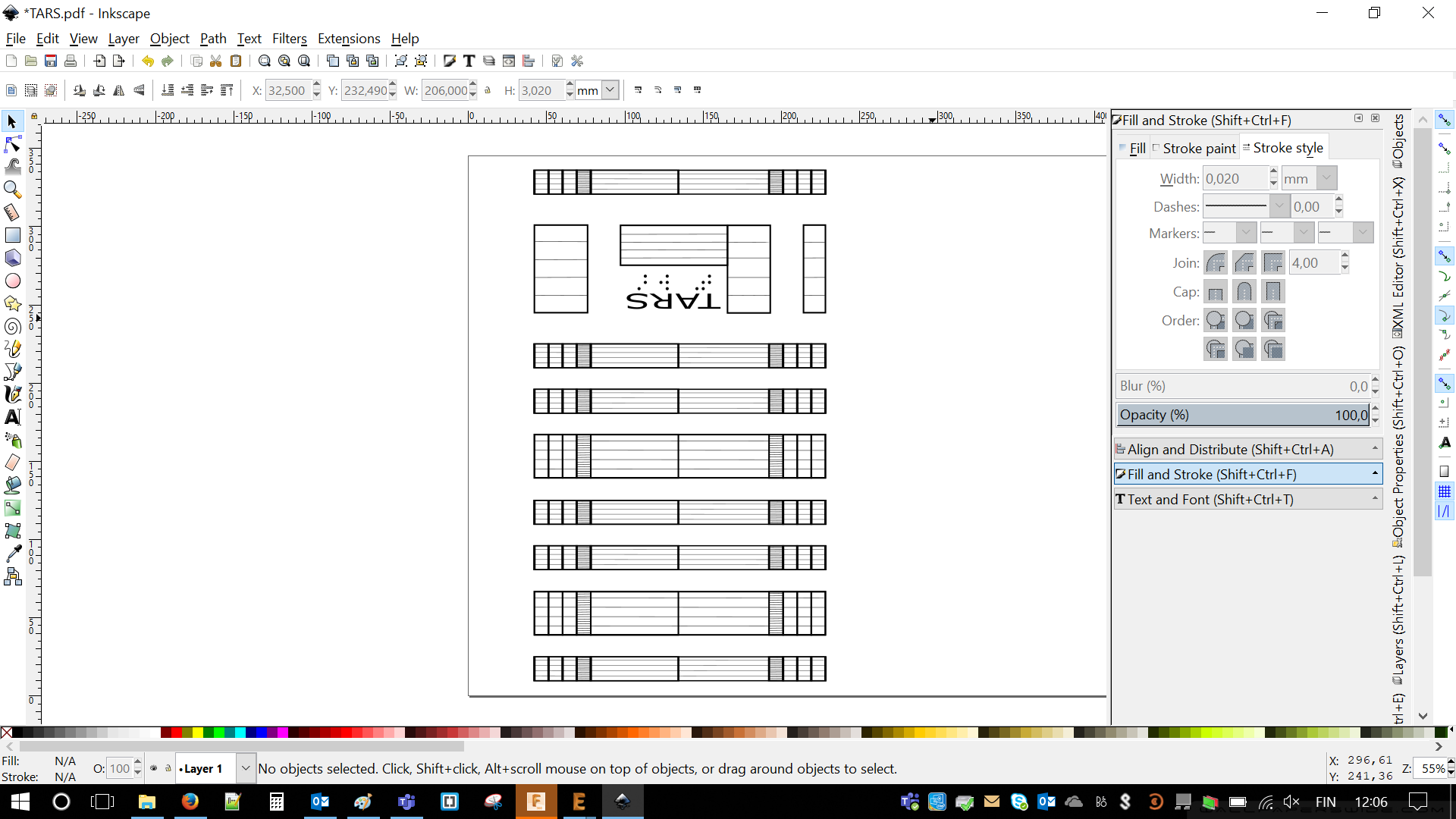
As I was not engraving anything before I prepared a little comparison of line width. Usually lines, which are going to be cut trough are not visible. Nevertheless, they are really there. This is a proof.
 |
 |
3D Modeling with Fusion360
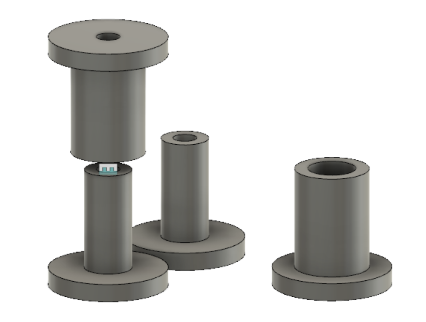
I never planned any movement. However, I created two pair of pins, which could allow robot's movement. Those are featuring holes for powering wires as two circuits will be located in TARS arms. Pins were designed with Fusion360.
Design was very simple as I knew size of the holes it required two sketches and a bit of extruding
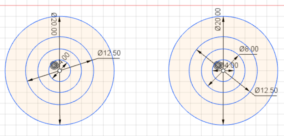
It required pinch of imagination and caliper to extrude those pins. I'm happy with a fact that estimated time of printing was equal less than 30 minutes and used material was exactly 7 [ccm].
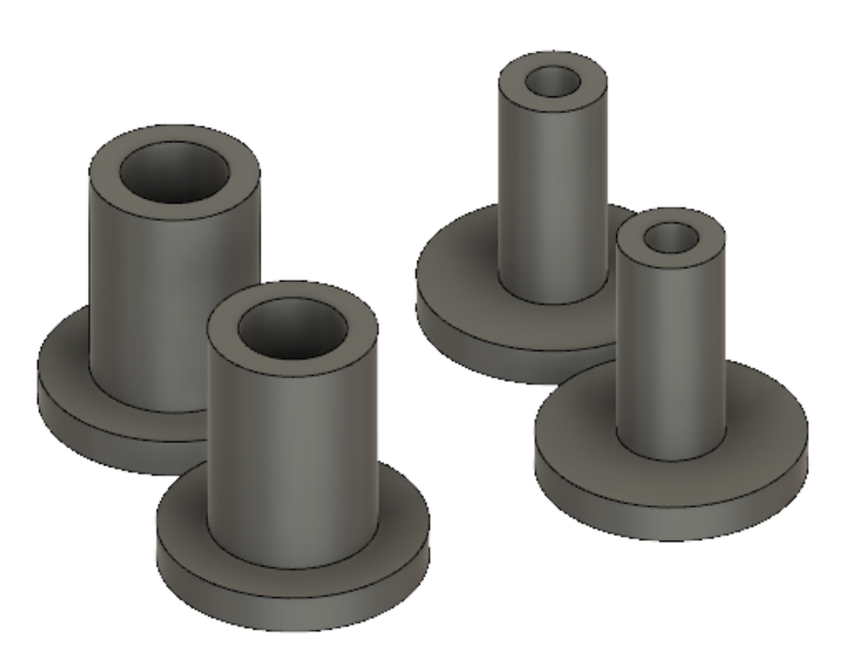
Just to be sure I aligned everything together and moved parts to check if nothing overlaps and pins fit to each other. Somehow I felt that I don't want to print those parts again, especially at this time 3D printer was heavily loaded.
Hero shot
This part of workload was learn during following:
Troubleshooting and conclusions
It is important to left some tolerance in fitting parts. It is enough to leave around 0.2 [mm].Without it there is a bit of scratching or work with sandpaper required.
In case of laser cutting it is important to remember about line width, 0.02 [mm] will be cut, where wider lines will be engraved.
Different sort of glue can be used to ensure MDF connections. Consider it as gluing paper to paper.