5. Electronics production
In this week, I made an in-circuit programmer, milled a PCB and programmed it. In the group task, we characterized the design rules for the PCB production process by trying different milling bit diameter sizes and cutting depths.
Group assignment
- Characterize the design rules for your PCB production process
The group work was done with Michael and Arash.
mods
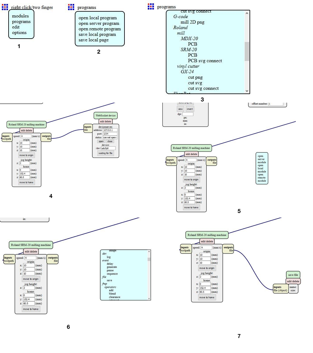
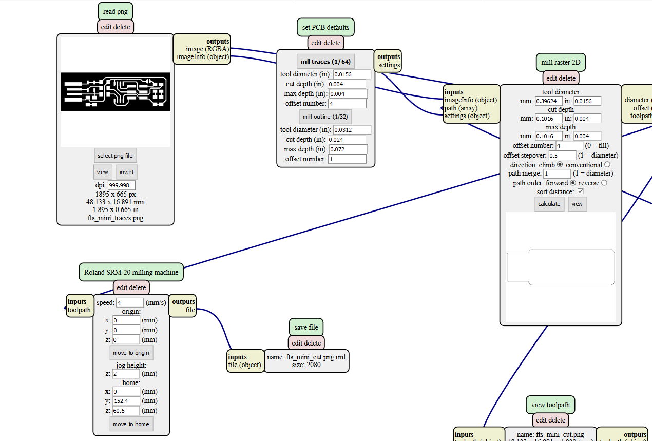
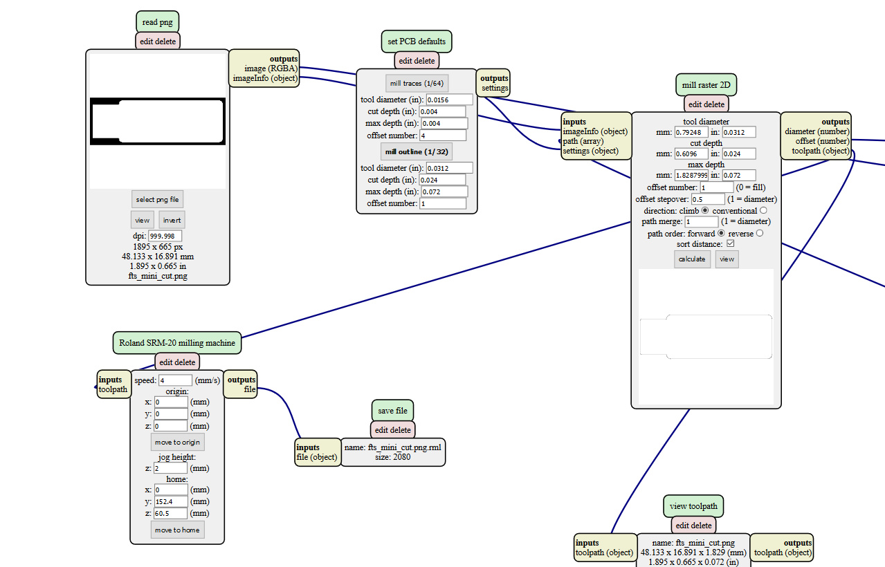
The following procedure was done at mods to generate the required files. As shown in subfigure 1, right click and select programs. Then select “open server program”, then choose Roland/mill/SRM-20/PCB. After this the default program will open which wants to communicate with the Roland over sockets, but since in our case Roland is not connected to the same PC, so instead of sending the output to a socket we send it to a file. So as shown in subfigure4, delete the websockets module, right click to add a new server module called file/save. Connect the input port of this module to the output port of “Roland SRM-20 milling machine” output port.
|
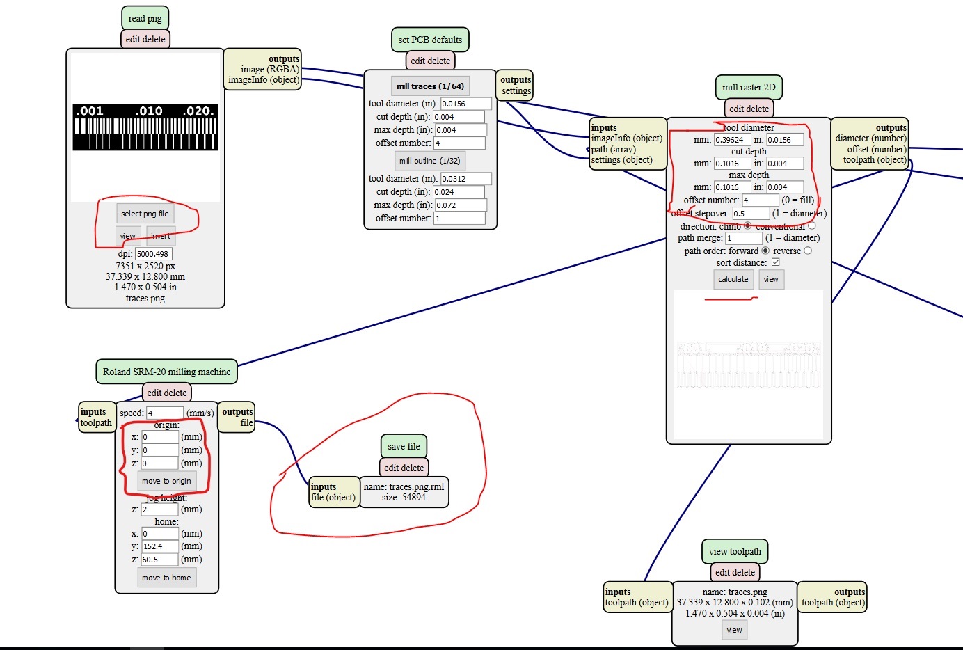
We used the mods software to generate the rml files needed by the roland cnc mill. In the picture below we have marked with red all the places where some change was done. In the top left corner, we had to put in the png file name. In the right corner we have the tool settings. In the middle “mill traces” is selected as we are milling the traces and not cutting the outline. In the bottom left the origin is set to 0,0,0. These are the rml files for milling traces and cutting the outline.
|
Milling Process
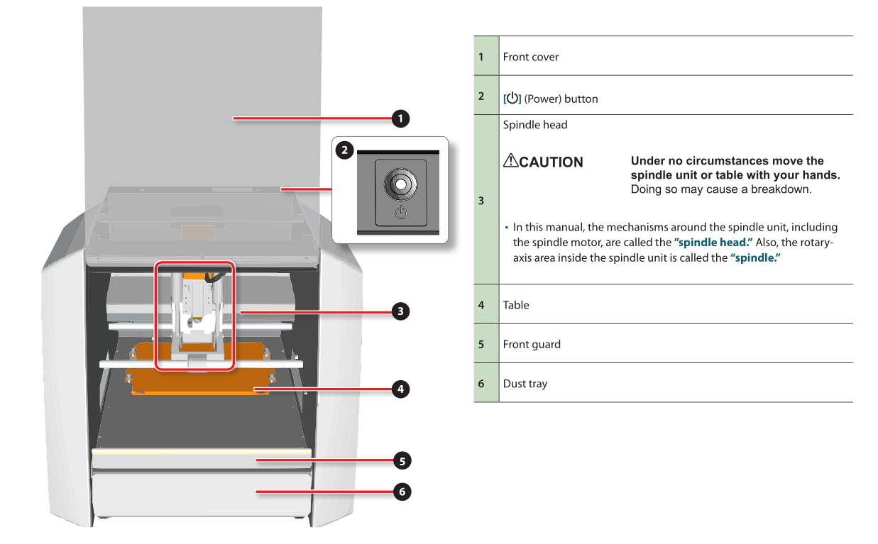
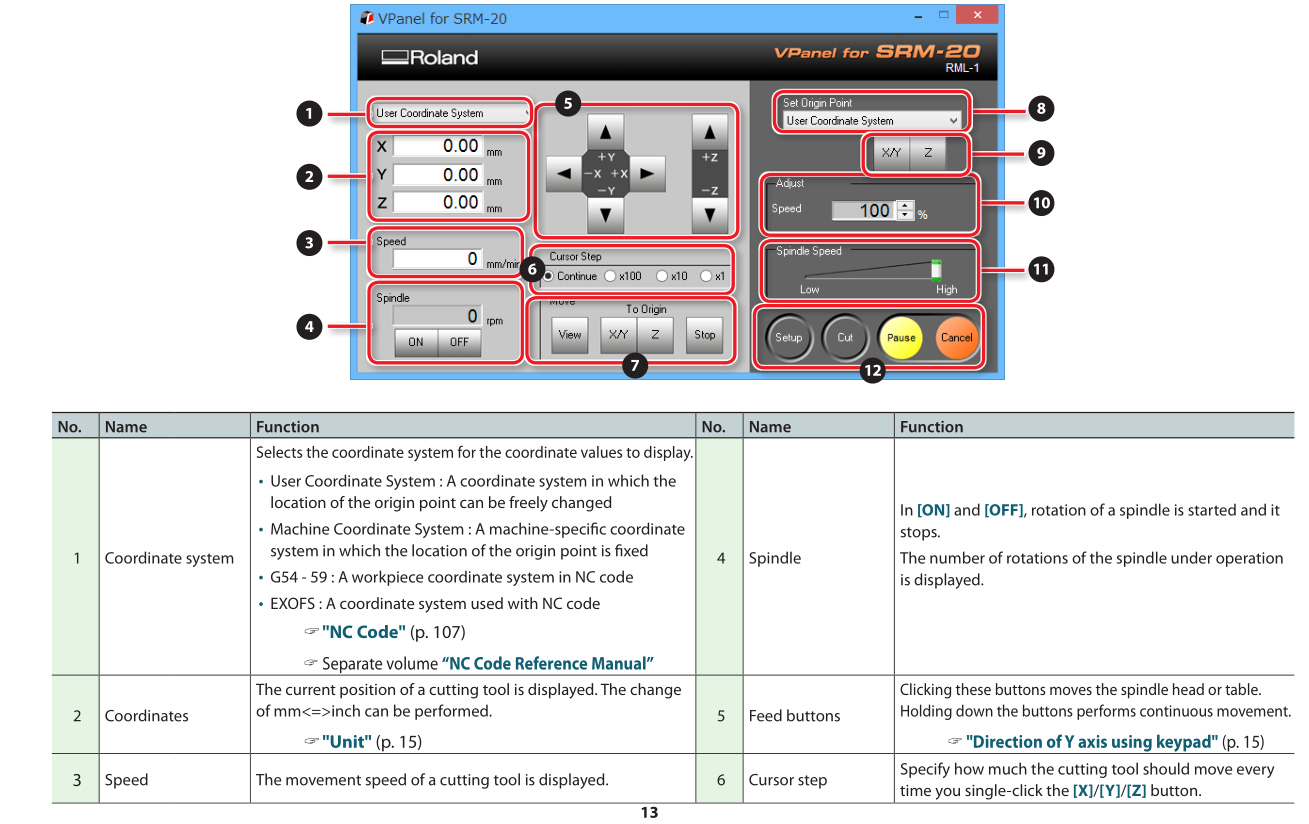
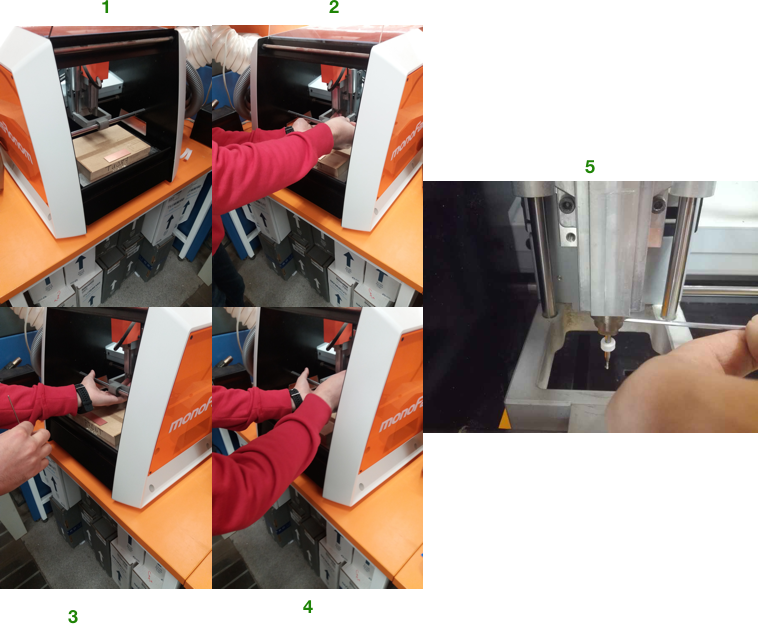
For the milling, we used a Roland SRM-20 milling machine. In order to operate the machine, you need to turn it on from the top right corner. Below are screenshots of some of the important pages of the SRM-20 manual. The manual can be downloaded from here.
|
|
|
|
|
|
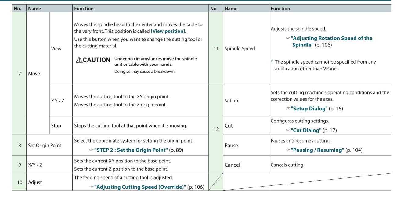
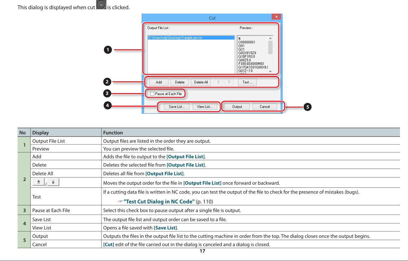
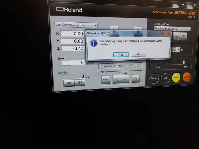
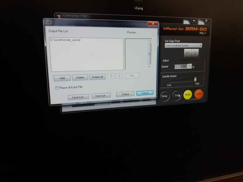
X/Y button on the VPanel software (No. 9). Then position it vertically and when the bit is near the board, you should loosen the collet with the hex key and carefully lower the bit to the surface of the board. Save the Z origin settings using the Z button on the VPanel software (No. 9). Finally upload the file to be milled by first pressing Cut button on the VPanel software (No. 12) which will open a dialogue box where you will ‘Add’ the file and the press ‘Output’ which will start the milling process.
|
|
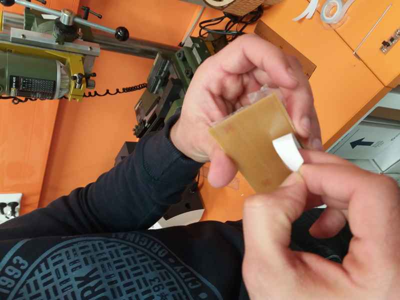
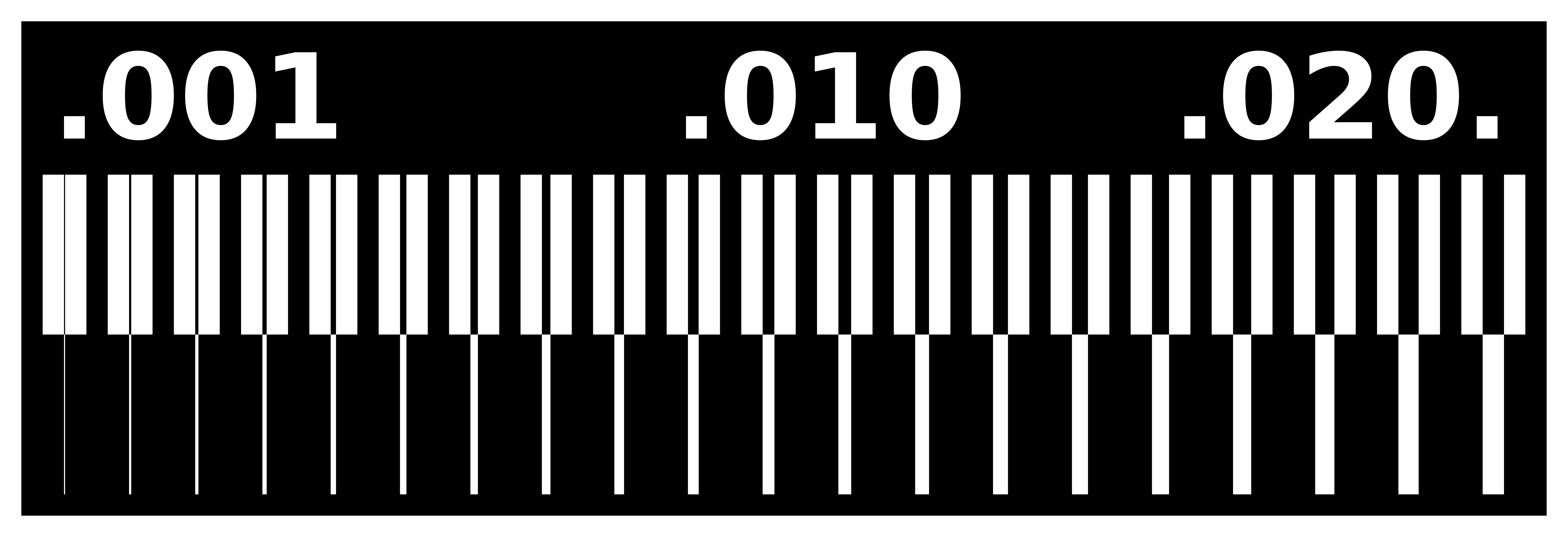
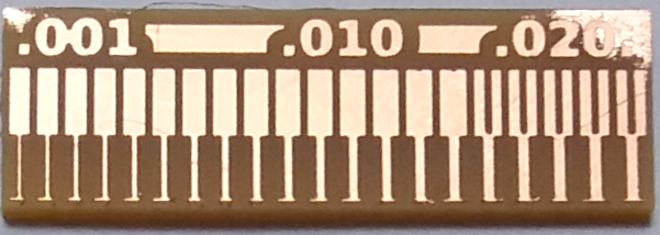
We used 3 different parameters (shown in the table below) for the milling bits. We first milled the PCB with a flat bit of diameter 0.4 mm with a cutting depth of 0.1 mmm. Then for the other two we defined the diameter settings in the software of the program.
|
| Tool | Cutting Depth Setting | Tool Diameter Setting | Output (Actual) | Design Rules |
|---|---|---|---|---|
| Flat - 0.4mm | 0.1mm | 0.4mm |
|
Thinnest trace: 1 mil, Spacing b/w traces : 16 mil |
| V Shape | 0.1mm | 0.2mm |
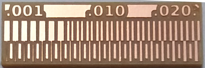
|
Thinnest trace: 5 mil, Spacing b/w traces : 8 mil |
| V Shape | 0.06mm | 0.1mm |
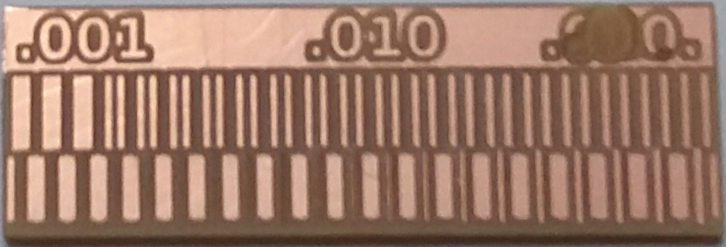
|
Thinnest trace: 14 mil, Spacing b/w traces : 5 mil |
Individual assignment
- Make an in-circuit programmer by milling the PCB
- Program the PCB
PCB Fabrication
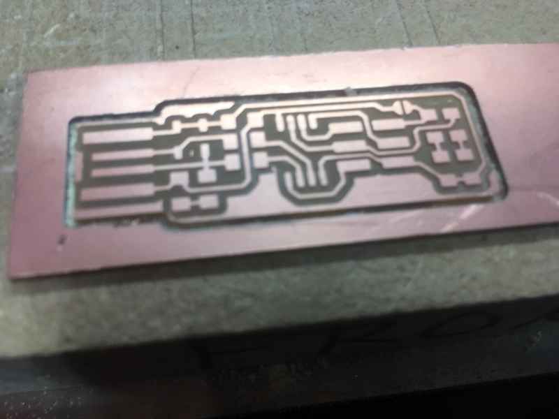
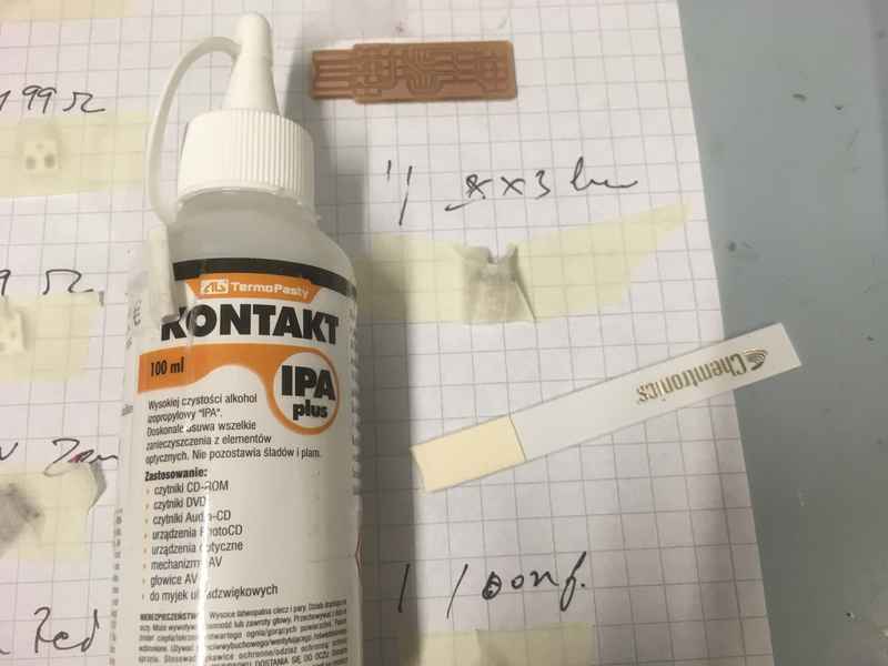
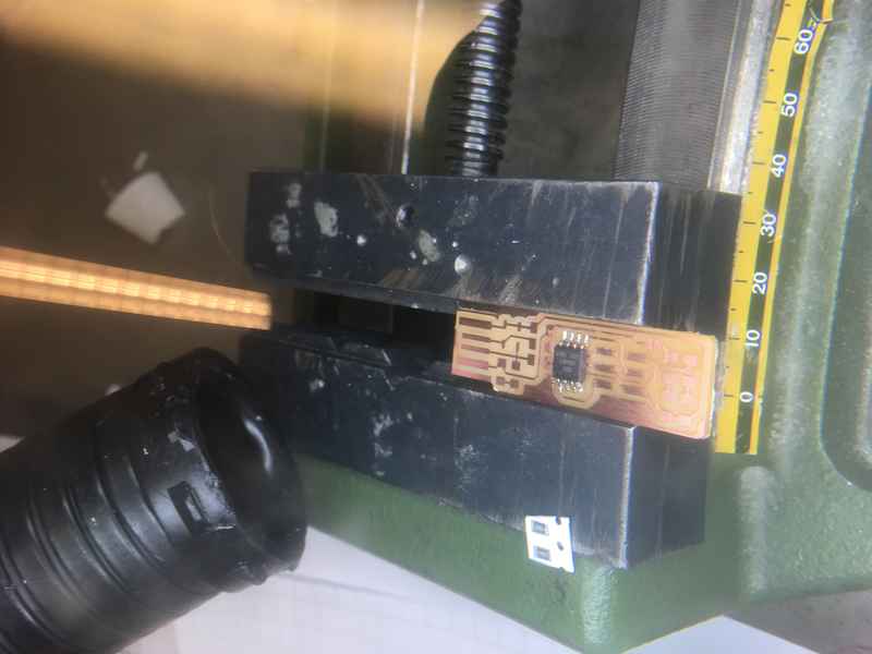
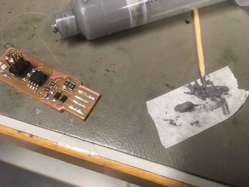
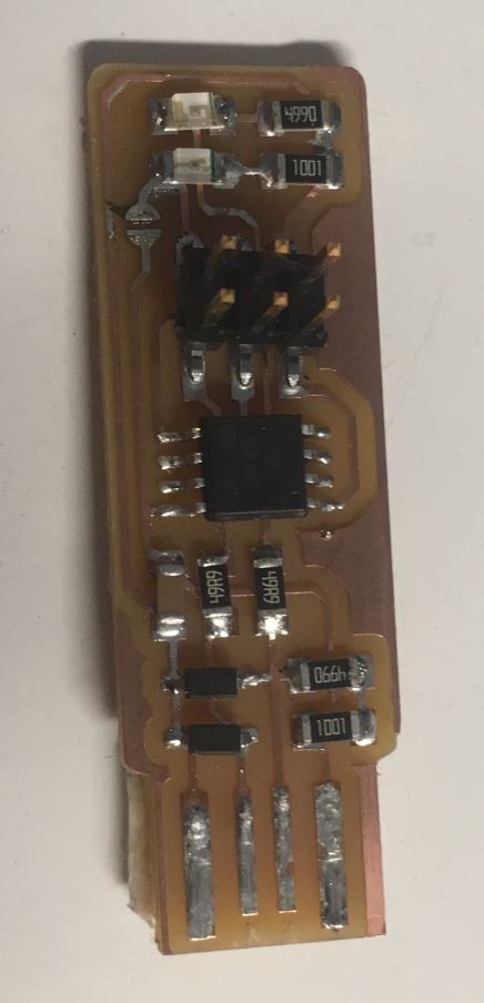
I used Brian’s version for the design.Below are the pictures for creating the rml files for creating the traces and outline. I used 0.4mm flat bit for milling and 1mm bit for cutting the pcb. These are the rml files for milling traces and cutting the outline. The finished pcb is shown below.
|
|
|
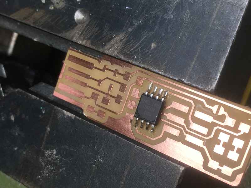
Assembling the PCB
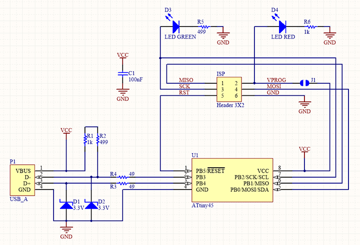
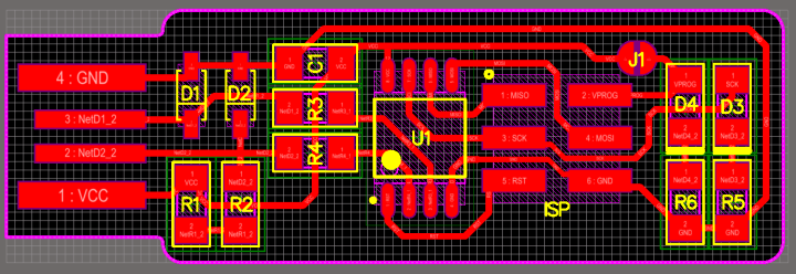
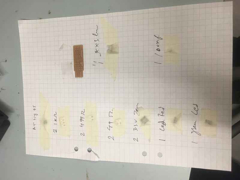
Below are the schematic, PCB layout and component list, as taken directly from Brian’s page.
|
|
| |
|
|
|
|
|
|
After soldering every component, I made sure that there was no short between the power pins and the relevant signal pins.
Programming the ATtiny45
Again, I took the source code from Brian’s page. Since I am using windows linux subsystem, I used the apt to download the required tools.
sudo apt install avrdude gcc-avr avr-libc make
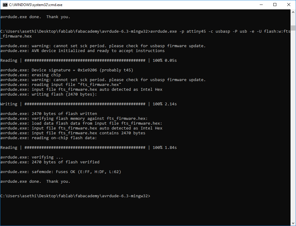
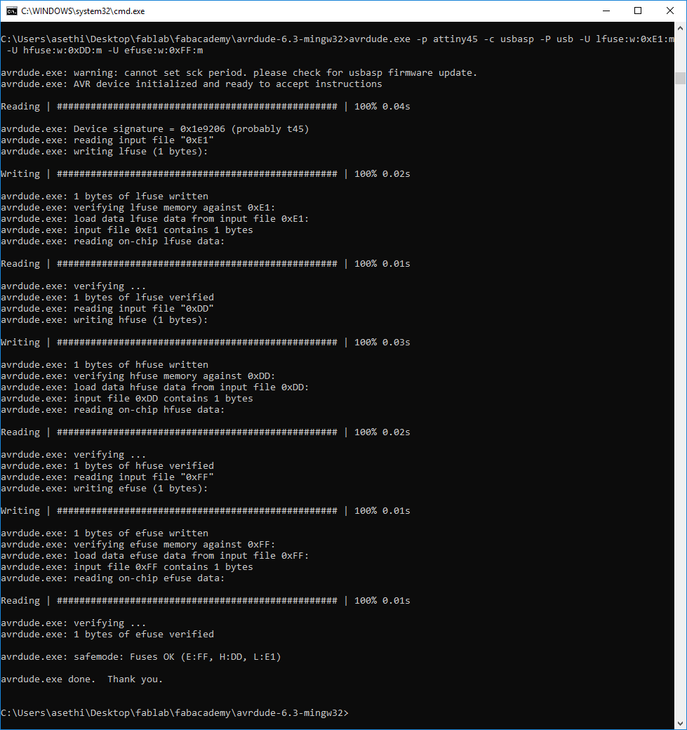
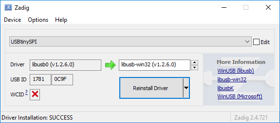
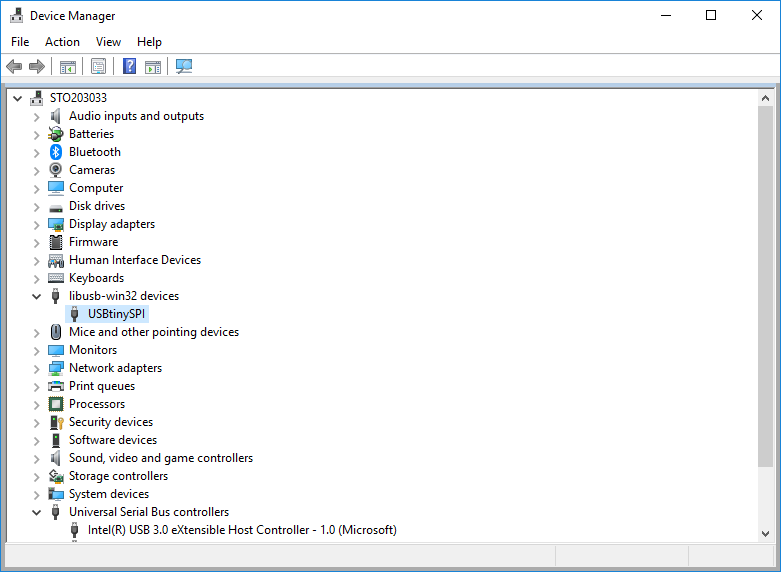
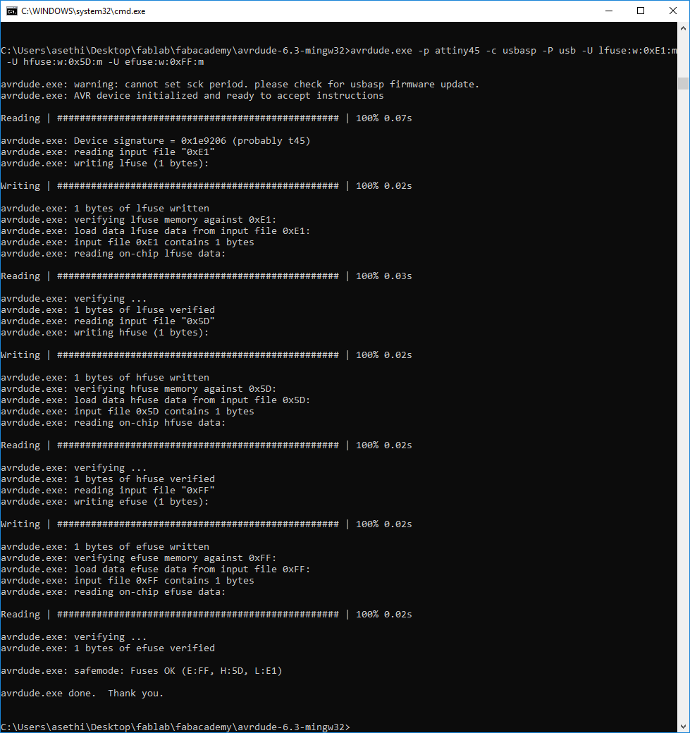
I compiled the code but soon found out that WSL does not support USB sub system, which meant I could not use WSL for programming the board. So, I got the windows binary of the avrdude and used that for programming. Furthermore, I was using usbasp programmer, so I had to change the commands for flashing the microcontroller. zadig was used to provide a generic signed driver for the windows. After successfully programming the microcontroller and verifying that it appears as a USB device, the reset fuse was blown. After that VCC was disconnected from the VPROG pin on the ISP header by removing the bridge on the solder jumper.
|
|
|
|
|
|
|
|
Files
Problems
-
Emergency stop by the Roland mill. While going through the third pass of making the outline, I got the following message on the PC and it didn’t go away till I pressed the power button. I was worried that I would lose the origin but after turning the machine on again, the software was fine and it did remember the origin. What actually caused the problem, that I don’t know.
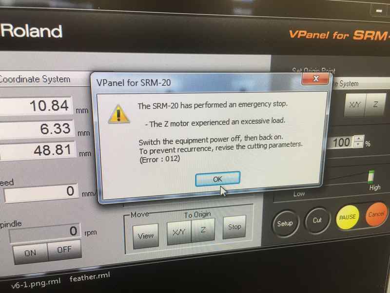
Emergency stop by the Roland mill. -
Windows linux subsystem does not handle the USB sub system, so could not use avrdude in WLS to program the microcontroller.