_stage 2
Sensors+programing
The logic of the project
I started the project with the idea of using solenoids as my triggering system to lock and unlock the
door. I followed up two main tutorials to understand the function and how to use an RFID reader and
solenoids as a locking system:
1_DIY smart lock with Arduino and
RFID, which I tested during STAGE 1 I modified the code and it all worked smooth.
2_RFID Cat Door,then I tested and
studied this code which has a lot of useful resources and inputs. But after setting up the code with all
the components I was having issues controlling the and triggering the solenoids when reading the tag.
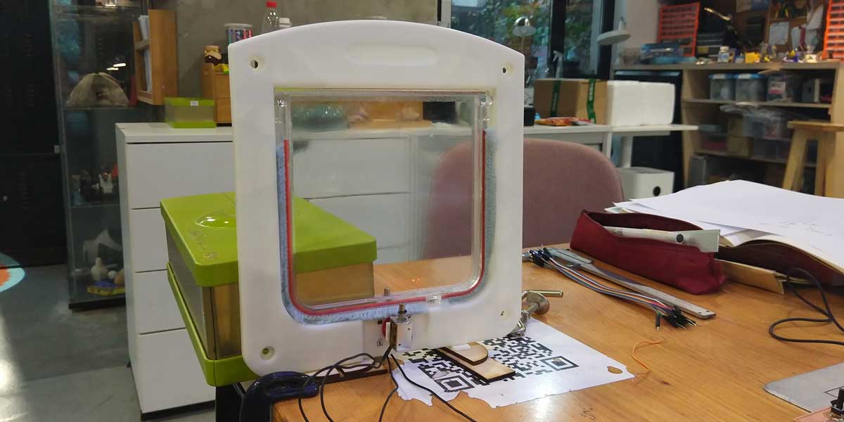
I bought an existing product, a flap door for cats/dogs to study it and to test it while figuring out how
the sensors work and what I needed to develop. This was a good exercise that helped me to visualize and
understand better my project.
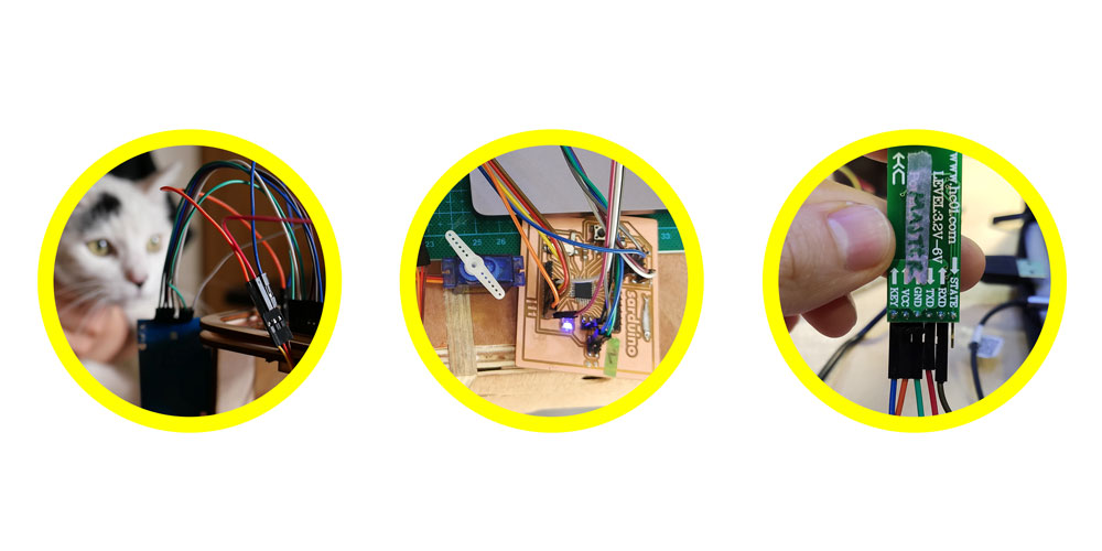
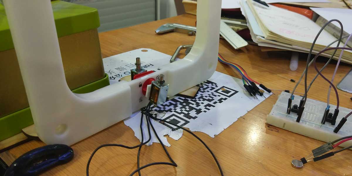
Here are some photos of the second iteration I tried for the door locking system:
These trials took me some time to work through, so in parallel, advised also by my instructor, I started trying to use a 5V servo motor to use how it worked for the triggering system.
After long trials I decided to use a servo motor instead for the locking system. Why?
1_I was having some difficulties with the solenoids and I was trying to work in series as Neil always
recommend us, and I noticed I was loosing more time figuring out the right code using solenoids.
2_I also tried to design an interface where the user could control the solenoids via Bluetooth. So I
started to use MIT app inventor
together with a bluetooth module, and i tried to control the solenoids like any other output device, to
say an LED, and it was not so simple to make it work, but instead with the servo motor it worked the
first time.
The documentation on how I built the app and used the bluetooth module is STAGE 5.
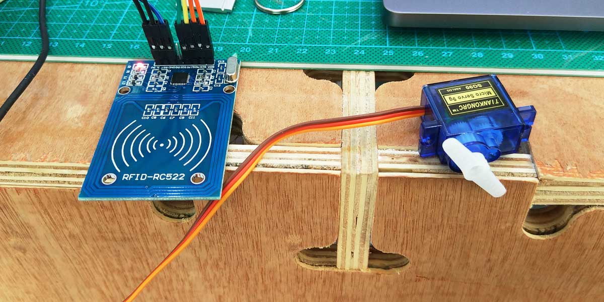
RFID & SERVO MOTOR
I found some useful documentation online on how to use a servo motor and an RFID tag reader that helped
me to develope my project.
Some of the tutorials I found very useful, and that helped me to program the locking system of my
project are:
1_RFID lock door
2_Arduino RFID Servo Box
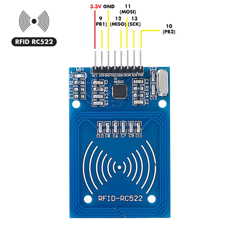
First thing to point out is the sensors I will be using at this point and their pinout for both the servo
and the RFID tag
reader: (for more details about the type of module I am using go to STAGE
1)
After understanding a bit more how I could use a servo motor and an RFID tag reader for my locking
system, I modified an existing code from
viral science website
adapting it to what I needed.
This is how it looks like the first code I started to use to move the servo motor to unlock the door
when a certain tag ID is recognized:
*
Servo moves when RFID reads recognized tag
Version1_works fine
//inspired on: Viral Science tutorials
//---RFID + SERVO MOTOR = MIRRU IN MIRRU OUT CODE---
//adapted and modified by Pamela Martello
//04 June 2019
Pamela Martello
*/
#include SPI.h> //peripheral communication
#include MFRC522.h> ///RFID library
#include Servo.h> // Servo library
#define SS_PIN 10 // RFID PINS
#define RST_PIN 9 //RFID PINS
#define ACCESS_DELAY 10000 //delay open the lock 10,000millis=10secs
#define DENIED_DELAY 1000
MFRC522 mfrc522(SS_PIN, RST_PIN); // Create MFRC522 instance
Servo myservo; // create servo object to control a servo
//int pos = 0; // variable to store the servo position (not needed)
void setup() {
Serial.begin(9600); // Initiate a serial communication
SPI.begin(); // Initiate SPI bus
mfrc522.PCD_Init(); // Initiate MFRC522
Serial.println("Put your card to the reader...");
Serial.println();
myservo.attach(3); // attaches the servo on pin 3 to the servo object
myservo.write(100);
mfrc522.PCD_SetAntennaGain(mfrc522.RxGain_max); //If you set Antenna Gain to Max it will
increase reading distance it increases about 1-2cm
}
void loop() {
// Look for new cards
if ( ! mfrc522.PICC_IsNewCardPresent())
{
return;
}
// Select one of the cards
if ( ! mfrc522.PICC_ReadCardSerial())
{
return;
}
//Show UID on serial monitor
Serial.print("UID tag :");
String content= "";
byte letter;
for (byte i = 0; i < mfrc522.uid.size; i++) { Serial.print(mfrc522.uid.uidByte[i] < 0x10
? " 0" : " " ); Serial.print(mfrc522.uid.uidByte[i], HEX);
content.concat(String(mfrc522.uid.uidByte[i] < 0x10 ? " 0" : " " ));
content.concat(String(mfrc522.uid.uidByte[i], HEX)); } Serial.println();
Serial.print("Message : ");
content.toUpperCase();
if (content.substring(1) == " 09 5E BB 59") //change here the UID of the card/cards
that you want
to give access (to know the code use examples inside MFRC522>DumpInfo)
{
Serial.println("Authorize mirru access");
Serial.println();
delay(200);
myservo.write(0);// lock position
delay(ACCESS_DELAY); //delay to keep the lock open and let the cat go in
myservo.write(90); // unlock position
}
else {
Serial.println(" CATccess denied");
delay(DENIED_DELAY);
}
}
With the antenna set to Max the tag can be read up to 4cm, without the max gain activated the distance reading is up to 2.5-3cm of distance.
Until this point my main source of information for the programming was this tutorial Arduino RFID Servo Box , and the previous code I used during STAGE 1
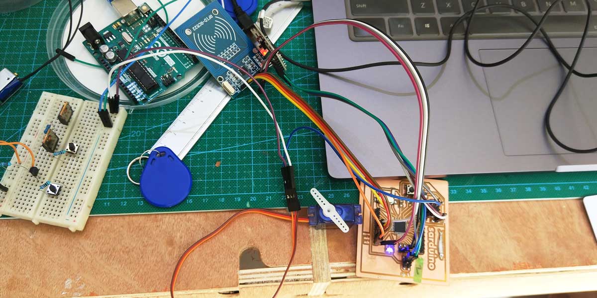
Here are some photos and videos of how it works.
As the locking system doesn't require big force to block
the door, I decided at this point that I would stick to use the servo for my system instead of the
solenoids.
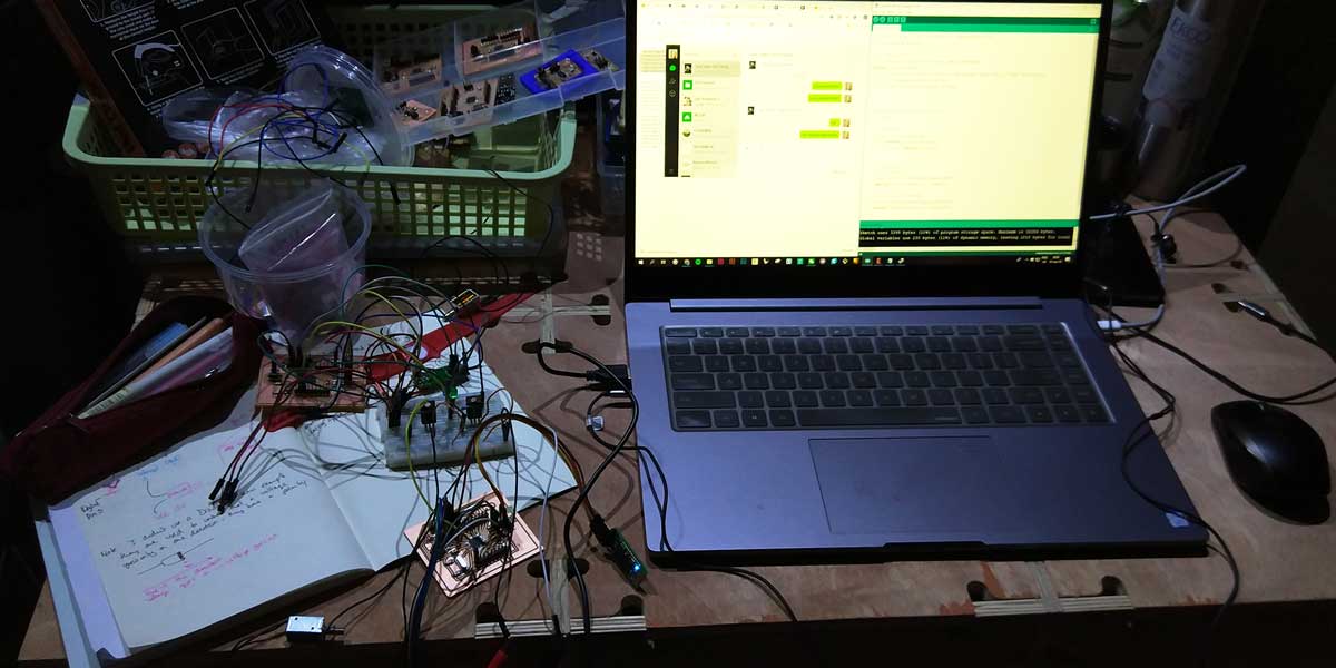
This is how my brains looks like these days...
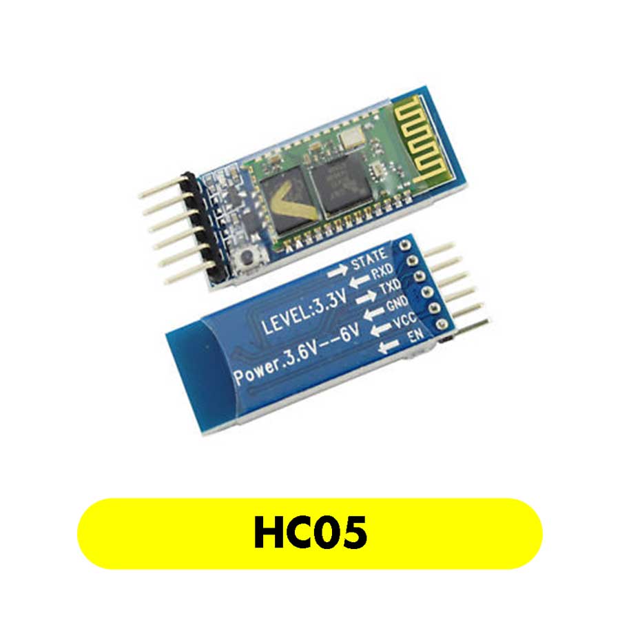
RFID + SERVO + BLUETOOTH
Once I had this code working, (always working on spirals in the meantime I was working on the PCB design and the structure), I decided to integrate a Bluetooth module HC05 as part of my plan was to design an App to control the opening and closing of the lock.
As using the bluetooth module for my project involved several tasks, I divided the documentation as it
follows:
_1 On this page you will find infrmation about the code I wrote for Arduino (the latest version I
used)
_2 You will find all the information about how I created the app inside the STAGE 5
_3 You will find the information about the integration of the module into the PCB inside STAGE
3
So first thing I started by reading and watching some tutorials about how to use a bluetooth module to
control a servo motor and how to design an app using MIT app inventor.
Some useful tutorials that helped me greatly to create my next code were:
1_
About MIT App
inventor
2_
Control 2 DC Motors Via
Bluetooth
3_
RGB LED with Arduino and
Bluetooth
4_ The documentation and wise advices from
a
Kirk
a FabAcademy graduate from Taiwan that also works in our lab.
THE FUNCTION OF THE BLUETOOTH MODULE
Basically the function of the bluetooth module is of a messanger between the code I wrote on Arduino IDE
to control the sensors and with the app.
The bluetooth will receive and send a message (and vice versa) between both codes, enabling the
communication between them and as a result controlling the opening and closing of the door.
To develop the app you need to integrate into the Arduino code certain integers, enable the Bluetooth.begin inside the void setup (works under 115200 baud rate), and add the set up inside the void loop. Inside the void loop you have to assign the states that you want to communicate to the bluetooth module, in my case I have two states to assign which are open & close so I assigned a character for these two states that I would then recall on the app code.
I explain more in depth the pin out of the bluetooth inside
assignment week 14, but is important to remark that the
bluetooth pins RX and TX can't be used at the same time if you are using an FTDI cable as this
works with RX/TX to tranfer-receive information.
You need to either disconnect and re-connect while programming it or you can connect as well to pin 10
and 11, but as I am using pin 11 (MOSI) for the RFID pin out, I had to find another solution.
From Kirk's documenation, mentioned above, I found out that he used the following pinout to connect the
bluetooth module to its mcu:
TX pin 6 PD6
RX pin 7 PD7
After all the previous considerations I re-wrote the code and this is the I will be using to control the servo motor, RFID tag reader and the integration of the bluetooth module:
/*
//MIRRU IN MIRRU OUT
//CODE TO CONTROL OPENING SYSTEM
RFID+SERVO MOTOR+BLUETOOTH
//latest version
//17 June 2019
Pamela Martello
*/
//For Bluetooth communication//
#include
SoftwareSerial BT(6,7); //TXD,RXD pin for Bluetooth module
#include SPI.h> //peripheral communication
#include MFRC522.h> ///RFID library
#include Servo.h> // Servo library
#define SS_PIN 10 // RFID PINS
#define RST_PIN 9 //RFID PINS
#define ACCESS_DELAY 10000 //delay open the lock 10,000millis=10secs
#define DENIED_DELAY 1000
//For Bluetooth communication//
int state; //the current state
int i;
int flag=0; //makes sure that the serial only prints once the state
MFRC522 mfrc522(SS_PIN, RST_PIN); // Create MFRC522 instance
Servo myservo; // create servo object to control a servo
void setup() {
Serial.begin(9600); // Initiate a serial communication
BT.begin(115200); //enable bluetooth communication
delay(3000);
SPI.begin(); // Initiate SPI bus
mfrc522.PCD_Init(); // Initiate MFRC522
Serial.println("Put your card to the reader...");
Serial.println();
myservo.attach(3); // attaches the servo on pin 3 to the servo object
myservo.write(100);
mfrc522.PCD_SetAntennaGain(mfrc522.RxGain_max); //If you set Antenna Gain to Max it will
increase reading distance it increases about 1-2cm
}
void loop() {
if (BT.available())//condition to find and read BT device //if the bluetooth is
available functions
{
state= BT.read(); //initialize reading
flag=0;
}
if(state=='O'){ //this is the message that will be sent to the bluetooth that will
enable the opening
myservo.write(0);
}
else if(state=='C'){ //this is the message that will be sent to the bluetooth that will
enable the closing
myservo.write(90);
}
delay(200);//delay between pressing open/close button
// Look for new cards-this is the loop for the RFID tag reader
if ( ! mfrc522.PICC_IsNewCardPresent())
{
return;
}
// Select one of the cards
if ( ! mfrc522.PICC_ReadCardSerial())
{
return;
}
//Show UID on serial monitor
Serial.print("UID tag :");
String content= "";
byte letter;
for (byte i = 0; i < mfrc522.uid.size; i++)
{
Serial.print(mfrc522.uid.uidByte[i] < 0x10 ? " 0" : " " );
Serial.print(mfrc522.uid.uidByte[i], HEX);
content.concat(String(mfrc522.uid.uidByte[i] < 0x10 ? " 0" : " " ));
content.concat(String(mfrc522.uid.uidByte[i], HEX));
}
Serial.println();
Serial.print("Message : ");
content.toUpperCase();
if (content.substring(1) == "09 5E BB 59") // MIRRU NECKLACE 09 5E BB 59
change here the UID of the card/cards that you want to give access (to know
the code of your tag use MFRC522 examples inside MFRC522>DumpInfo)
{
Serial.println("Authorize mirru access");
Serial.println();
delay(20);
myservo.write(0);// lock position
delay(ACCESS_DELAY); //delay to keep the lock open and let the cat go in
myservo.write(90); // unlock position
delay(ACCESS_DELAY);
}
else {
Serial.println(" CATccess denied");
// delay(DENIED_DELAY);
}
}
IMPROVEMENTS
_1 Make the servo move twice when closing, this will ensure the flap closes well in case it is not
aligned. I probably need to add a boolean function into the code.
_2 The delayI have now to keep the door open is not 10secs (is less like 7secs), somehow my delay
variable is not working properly, I need to revise this.
TASKS COMPLETED
_MCU PROGRAMMING ✔
_DOWNLOAD FILES
_SOLENOIDS code from tutorial
_RFID+SERVO MOTOR.ino
_RFID+SERVO MOTOR+BLUETOOTH.ino