_week 14
networking and communications
During this week our assignment consists on making two or more of our PCBs communicate through different protocols.
Group assignment
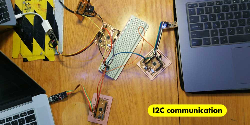
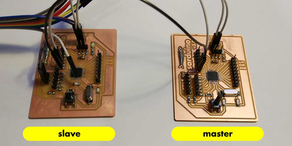
For the group assignment we decided to use I2C protocol using all our four satshakit
inspired boards.
But what exactly means I2C communication?
The Inter-integrated Circuit (I2C) Protocol is a protocol intended to allow multiple "slave" digital integrated circuits ("chips") to communicate with one or more "master" chips. Like the Serial Peripheral Interface (SPI), it is only intended for short distance communications within a single device. Like Asynchronous Serial Interfaces (such as RS-232 or UARTs), it only requires two signal wires to exchange information. *source sparkfun
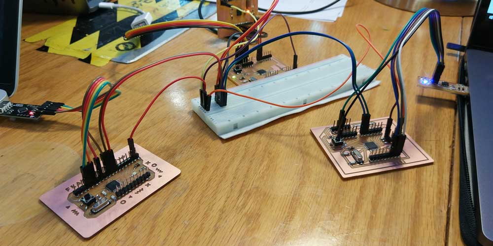
The I2C communication protocol works by setting up a MASTER and a SLAVE(S) connected by two
signal wires for communication, this is SCL (Serial Clock) and Serial Data
(SDA) connections.
Once you set up who is the master and who is the slave you have to upload a code into each of them to
start the I2C communication.
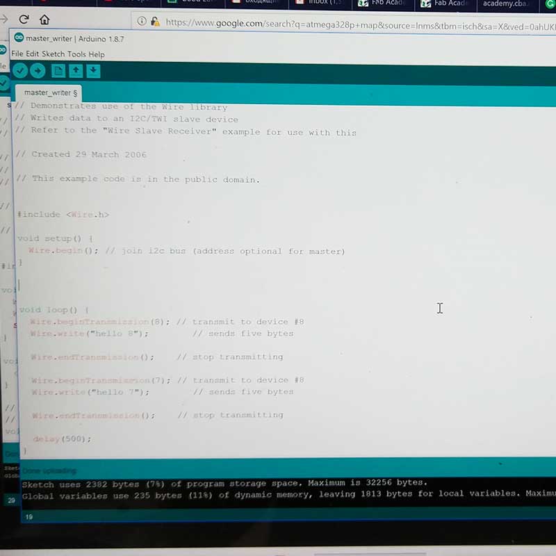
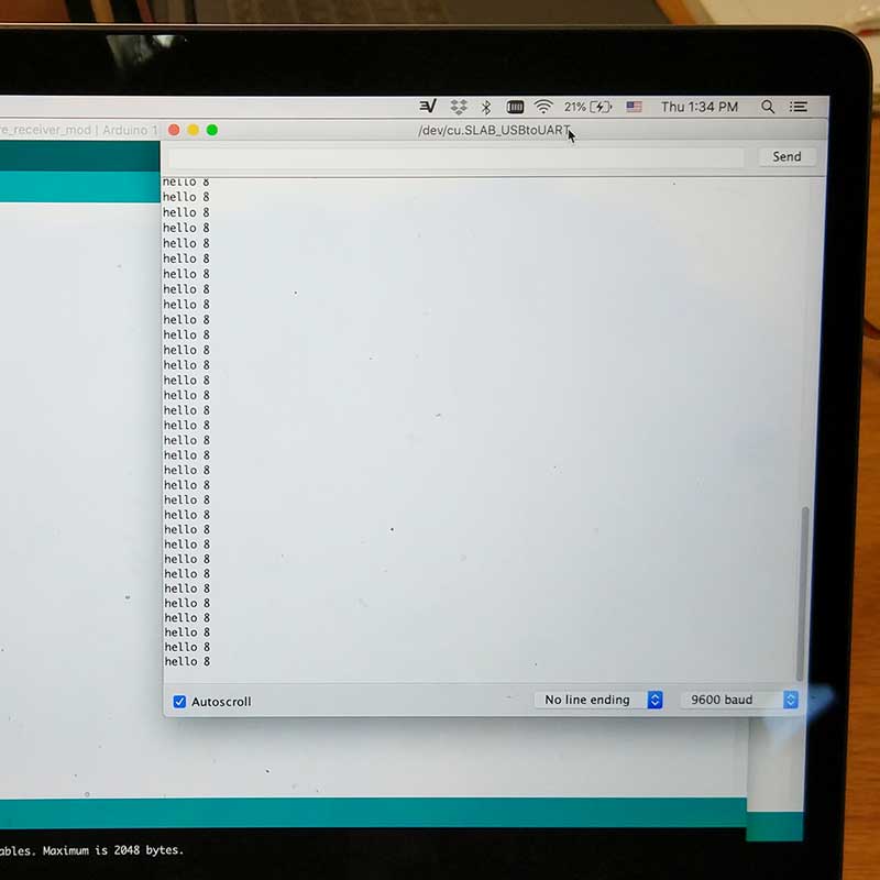
In our case we used Arduino IDE to upload the codes into the master board and the slaves. (Note that master and the slave(s) have their own code).
As we used 4 boards at the same time, we used a breadbord to share SCL (PC5), SDA (PC4),
VCC and GND.
The codes we used are available at the end of my documentation otherwise you can find them inside
Arduino IDE "wire" examples. Also, this week our classmate Flavie did the groupal
documentation, you can find more details about this test we did under this
link
.
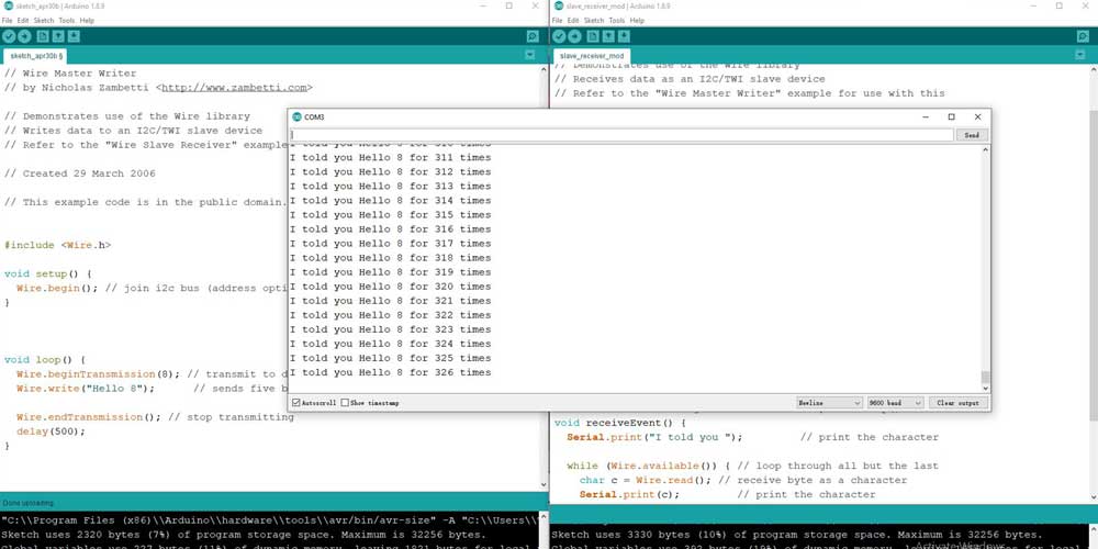
These series of photos show (from the left) the master's code, and the slaves serial monitor message that was displayed when uploading the codes and connecting them.

Individual assignment
_SARDUINO 3.0 iteration
Before starting this weeks assignment I decided to end this love hate relationship with my dear
Sarduino and find out the problem I was having with my FTDI connection.
It was a long week as it took me several days to mill and solder new boards and try to find out the
problem. I was quite frustrated and sad that things were not working fine every time I did a new board
or tried fixing the existing ones, but helped by my super instructor Saverio we found the issue and I am
super glad my boards are up and running!
The whole process is worth to document it so that I know next time what was the issue, how we solved it
but specially remind myself is worth the effort and the long nights spent at the lab trying to solve the
issues.
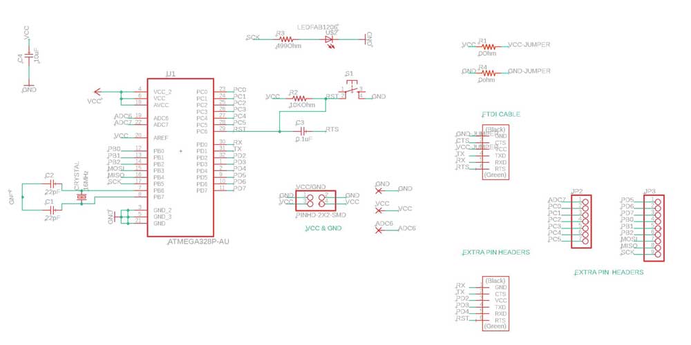
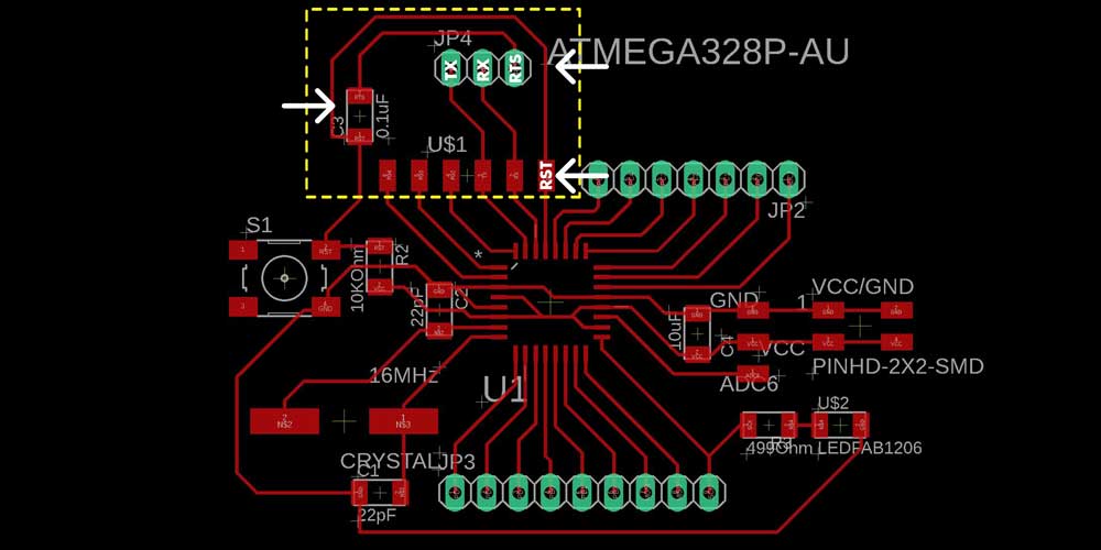
First thing I did was to redraw from scratch on Eagle my PCB, this way I could go over each connection
and component and try to see if I found any error. Before redrawing my board I checked carefully my
three classmates Eagle schematics and boards, even though we all did our own version of the Satshakit, I
thought it was important to analyze them crefully to see if there was any difference or error. I also
reviewed carefully the Satshakit.
At this point I couldn't find any issues, so I proceed to redraw my Eagle schematic/board being very
careful of using FabDesign rules.
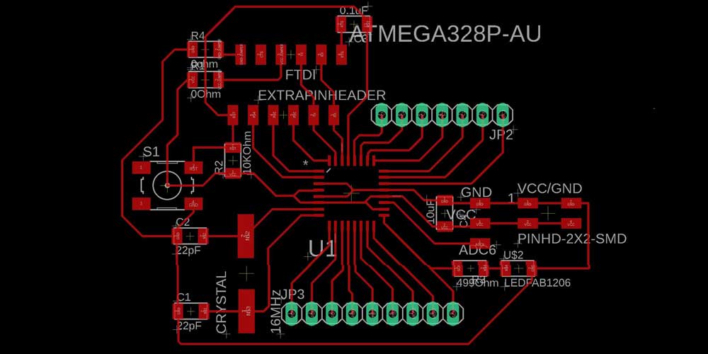
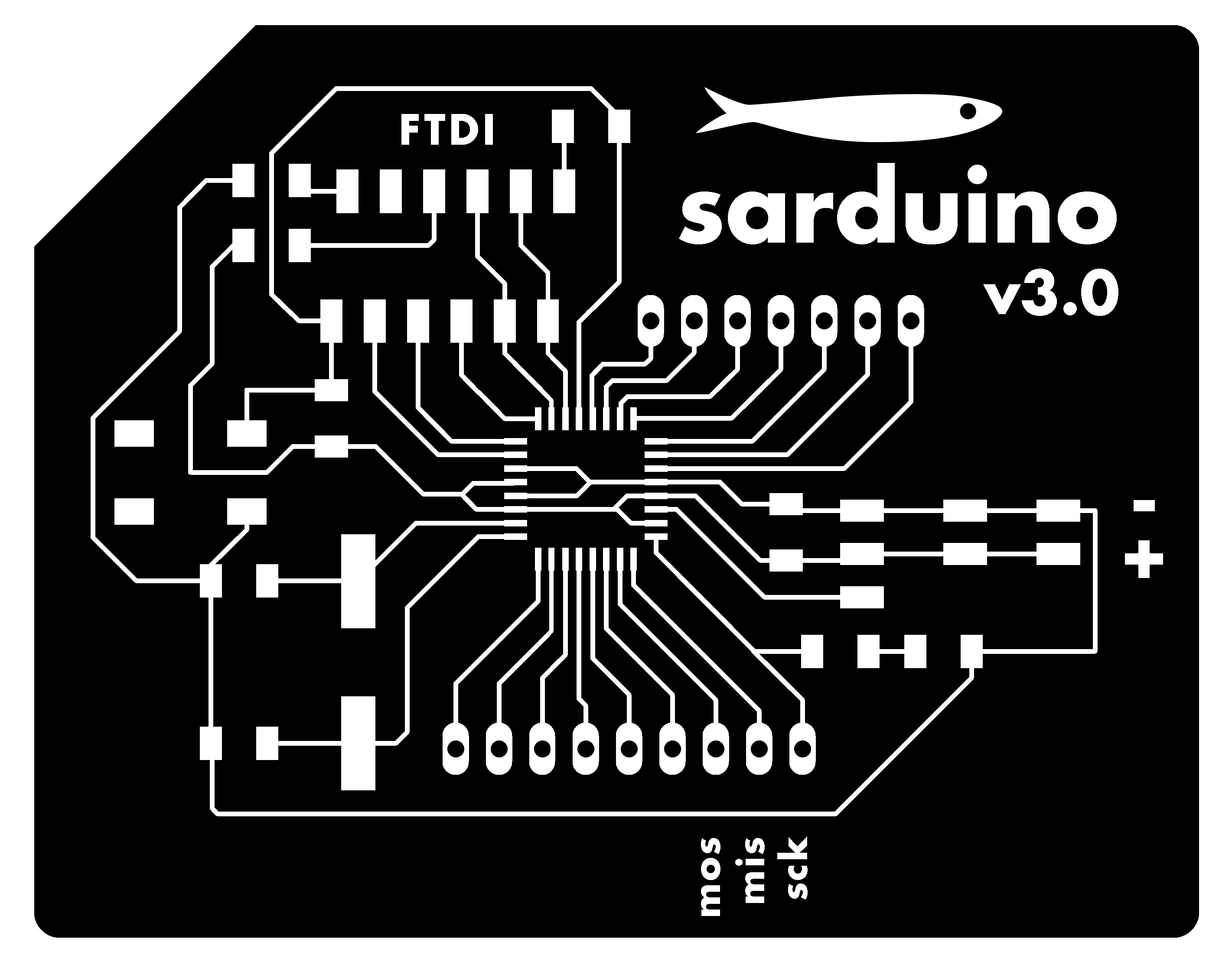
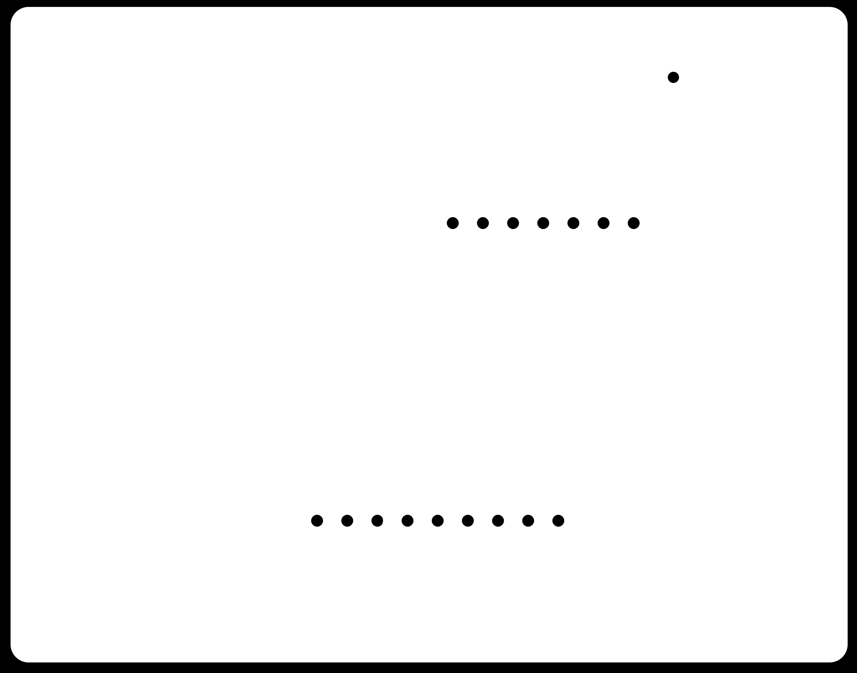
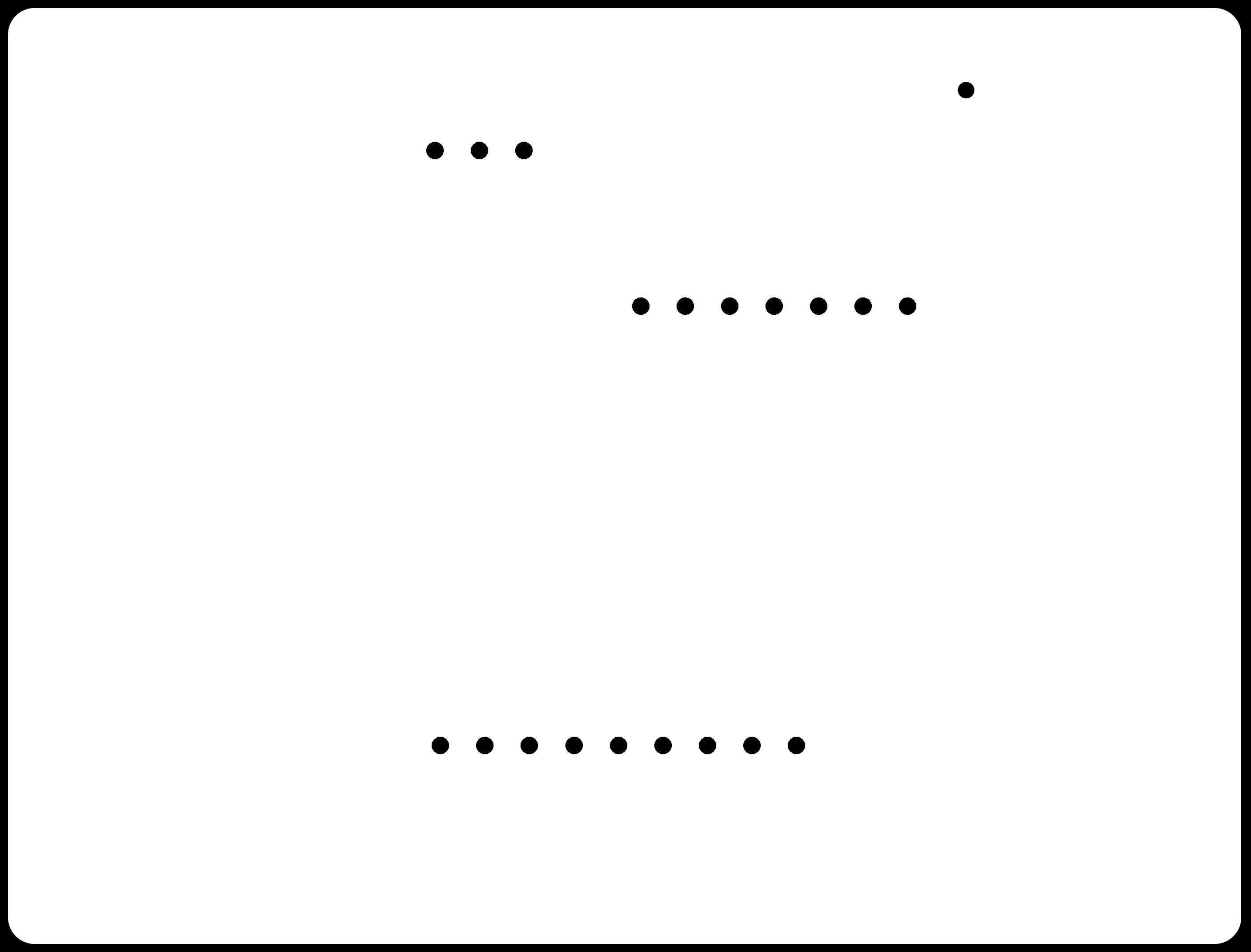
Here are photos of both the Eagle files and the final outcome once I milled and soldered carefully all the components.
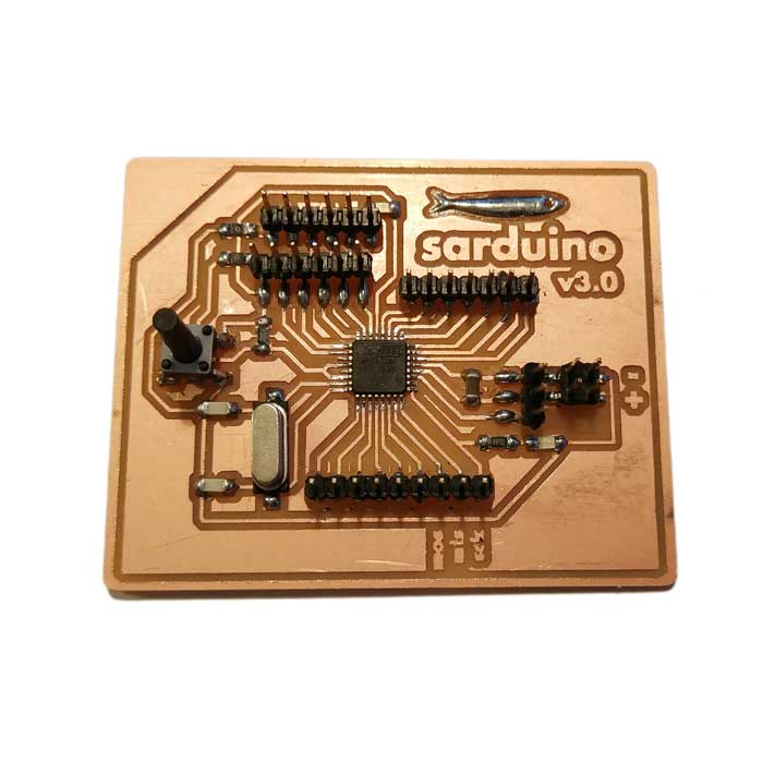
After redoing the board from scratch, milling it (cleaning it very well before soldering), then soldering
all the components carefully I proceed to upload a code using Arduino IDE through my FTDI connection.
And...
Same error as before the code uploading through my FTDI ports didn't work. I checked all the
connections, cleaned again, tried from another computer and using a different FTDI cable but nothing...
I could only use my FABISP to upload programs into it, same issue as the last two Sarduinos.
I had the sensation the problem was related to my RESET pin and the way I connected the 0.1uF capacitor, so again I decided to try a next iteration of my board and modifying the way I connected my RST and the capacitor.
_SARDUINO 4.0 iteration
One of my classmates Flavie, did a version of the Satshakit that worked since the beginning, so I decided
to analyze well here schematic and follow the way she connected RST and the capacitor ?(as I thought
this was the issue).
So I redraw from scratch a new schematic on Eagle, I checked carefully all the traces of the components
I was using (as I downloaded several libraries like the one of the ATMEGA328).
This is the schematic and board I did of the 4th iteration.
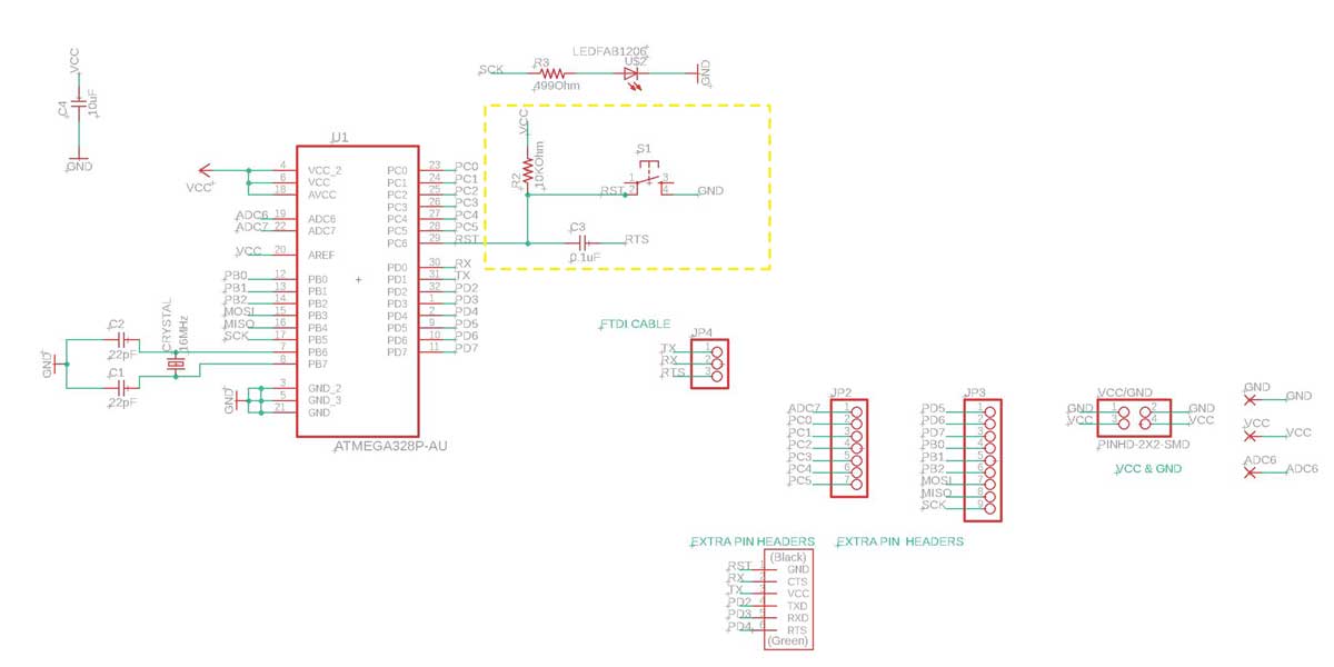
As you can see I modified the connections of RST and the capacitor on the board but not on the
schematic.
I then proceed to mill it and solder the components.

So... this was already Sunday late night, and I connected my board to see if I could upload a code
through the FTDI cable, and...it worked!
That moment I felt a relief I thought I had solved the issue on this new iteration. As I was not sure
this new model would work I thought it would be a good exercise to mill and solder a board that has been
tested and worked, and I thought of doing a Satshakit. This way I
could narror my possibilities of errors, if it worked it meant I did something wrong with my connections
in my Sarduinos, and if it didn't worked it meant that probably my soldering was not that good.

As I was interested in trying other codes for I2C communication protocol, so the next day I tried to use both the Satshakit and my new working Sarduino. And surprise! none of them worked the FTDI connection...
At this point I really thought I had a bad energy towards PCBs, I scratch my head and rechecked both boards connections, I cleaned very well the paths with a sharp knife, I tried different FTDI cables, I tried connecting the RTS of the FTDI cable instead to the RST pin on my pin headers, I tried on other computers, but it didn't work. All my boards under the same spell and I couldn't find the issue. It was weird that my last Sarduino worked the day before but now not anymore, I started to think that was all an illusion...
I couldn't go further on my assignment as I wanted to solve the problem, I am quite stubborn and although
Neil always advises us to work in spirals, I desperately wanted to solve this problem.
It took a
while to solve it, a couple of days of short sleep and help from my instructor... but we did it!
_SOLVING THE MISTERY OF THE FTDI CONNECTIONS!
WE FOUND THE PROBLEM!!!!!!
Thanks to the patience and help of Saverio, we managed to find the problem (although it is still strange why this happens and would be nice to know the reason behind it, will try to research more about it).
Somehow, when the problem was on the burn bootloader profile/settings we did from the first
to our ATmega328 through the Arduino IDE.
Saverio found out that when re-uploading the burn bootloader using the Arduino Pro or Pro
mini profile the FTDI connections worked perfectly fine after this, so we tried on all
my boards (including the Satshakit) to re-upload the bootloader using this profile. After doing this
they all worked! So we did a second test and after uploading this profile we did a third re-upload using
this time Arduino genuino/uno (which is the correct profile we should be using), and after
re-uploading this profile they all worked!
It is weird, but just re-uploading the bootloader using that profile it all seemed to reset and work fine. So now I have 5 working boards =) all this time and it was just the bootloader not my connections or soldering skills...
So, if you encounter a similar problem do the followinf steps:
1_Re-upload the bootloader using ARDUINO PRO/OR PRO MINI profile
At this point your FTDI connections should work (check)
2_Re-upload the bootloader with the correct profile ARDUINO GENUINO/UNO
your FTDI should be working!
Problem solved!!!!!
DISCLAIMER: this applies if you are using Arduino IDE
_I2C PROTOCOL
Ok! so finally I have my boards up and running, as I wanted to try a bit more the I2C communication first I tried using my boards the example we used during our group assginment, the master-slave code, to see if it worked fine.
After running this code I checked some other codes I could use to enable a chat conversation among two boards, and I found a simple code with a clear tutorial on how to do it (using Arduino IDE), on this website .
How it works? You just need two boards, upload the code into each of them and if you are doing it from
one computer as I did, you should open two different sessions in Arduino IDE (not windows but sessions)
to open the serial monitor of each board so that you can start chating.
The connections are very simple, first upload the code and connect each board using an FTDI cable
connection, then you need to connect the boards between them (obviously), using pins MOSI
and PB2 which will work as the RX/TX exchange channel of communication.
This is the code you have to upload on both boards:
/*
Simple Chat Program
Receives from the hardware serial, sends to hardware & software serial.
Receives from software serial, sends to hardware serial.
The circuit:
* RX is digital pin 10 (connect to TX of other device)
* TX is digital pin 11 (connect to RX of other device)
created 16 August 2014
modified 16 August 2014
by William Chang Wei Tan
based on SoftwareSerial example
modified by Pamela M
30 April 2019
*/
#include
SoftwareSerial chat(10, 11); // RX, TX
int text;
void setup()
{
// open hardware serial, TX = 1, RX = 0
Serial.begin(9600);
Serial.println("Starting Chat Program...");
// set the data rate for the SoftwareSerial port
chat.begin(9600);
delay(1000); // delay 1s to stabilize serial ports
chat.println("let's chat!");
}
void loop()
{
if (chat.available())
Serial.write(chat.read());
if (Serial.available())
{
Serial.print("Sarduino1");
while (Serial.available())
{
text = Serial.read();
chat.write(text);
Serial.write(text);
}
chat.println();
Serial.println();
}
}

_BLUETOOTH MODULE HC05
For my final project I used a bluetooth module as I wanted to design an application to be
able to control the opening and closing of the door.
So I will add on this assignmet the part related to this week's topic, and as I did an app as well, I
will add the documentation on how i built the app into the
interface and application programming week.
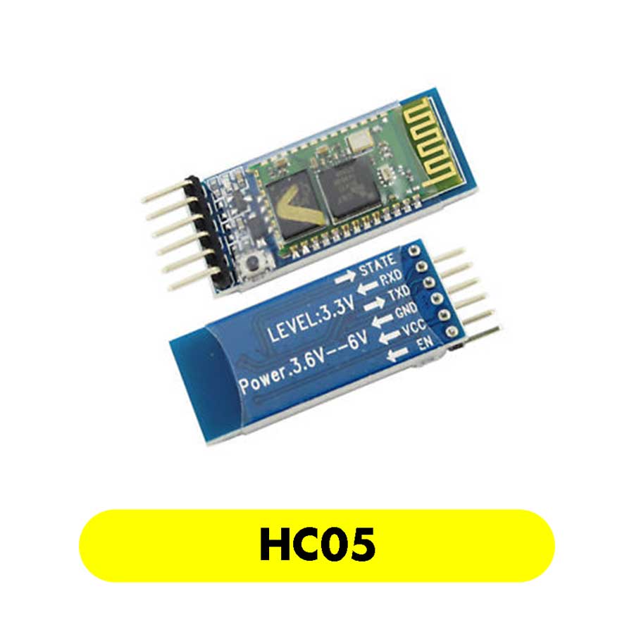
I am using the HC05 module which is a
SPP(Serial Port Protocol) module for wireless serial communication that allows you to interface with an
MCU.
The main characteristics of this module are (source:
instructables)
_1 Input voltage 5V
_2 This module can be set either as MASTER or SLAVE (will explain later what it means
and how to do it)
_3 Distance range 20-30m
_4 The pin out of this module is: GND-to GND, VCC TO 5V, TX-to RX, RX-to TX, KEY or EN-( pin used
to toggle between "Data Mode" (set low) and AT command mode (set high), by default it is in "Data
mode" source.) The button is used
when enabling the key/en to switch between Data and command Mode. STATE connects
directly to the LED on the board, serves to check the status of the Bluetooth connection. The blink
indicates the status:
Blink once in 2 sec: Module has entered Command Mode
Repeated Blinking: Waiting for connection in Data Mode
Blink twice in 1 sec: Connection successful in Data Mode
_5 The module communicates using USART (universal asynchronous receiver-transmitter) at 9600 baud rate
The HC05 module can be configured as a master or slave
_ESP8266
My target of this week is to understand how ESP8266 component works.
There are several models available in the market, I found out this two different chips being the one on the left a model from AI-Cloud TT-71 ESP8266 and the chip NodeMcu. I would like to use a wifi chip on my final project so that I can get data from internet about the weather forecast and possibly the AQI, therefore I decided to research a bit more about this chip during this week's assignment.
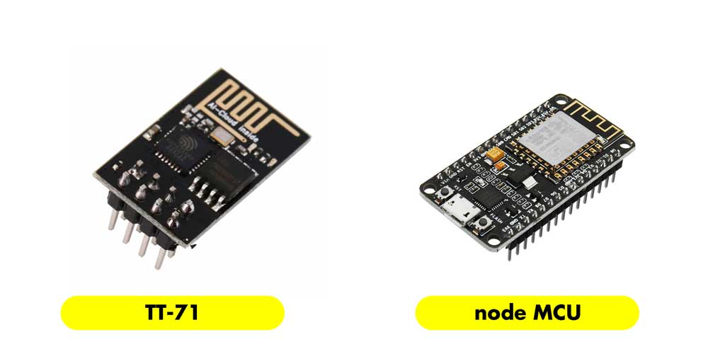
Both chips are a SoC (System on a Chip), the components consists of a and MCU (Tensilica L106 32-bit) and a WiFi transreceiver. This little chip has general purpose Input/Output pins GPIO and also analog input, meaning it can be programmed like any other MCU plus you can get Wi-Fi communication. (information source: ESP8266 tutorial).
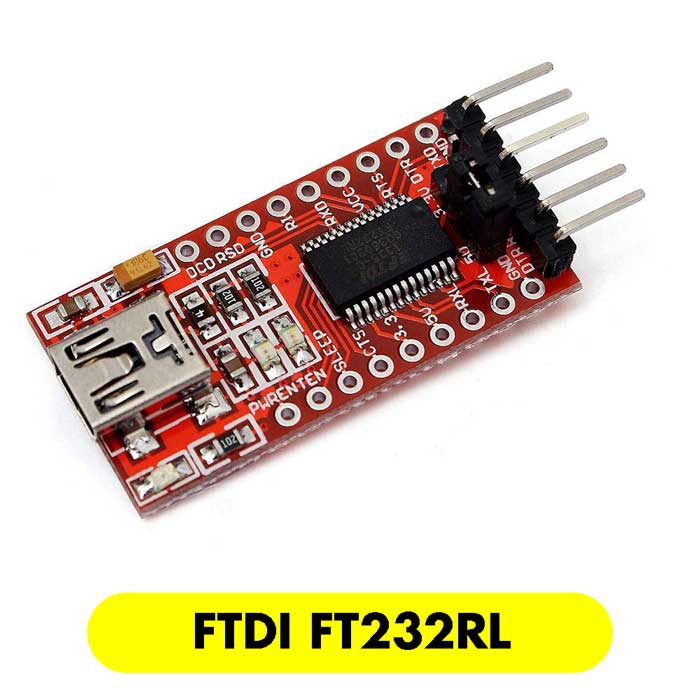
The chip TT-71 works with 3.3V, it is a very delicate chip if you provide more power you will kill it. The maximum voltage is 3.6V, also the I/O pins run at 3.3V. To program it you will need USB-to-Serial converter, you should use an FTDI FT232RL or a Logic Level controller which is pretty much the same, but I find more practical the FTDI FT232RL.
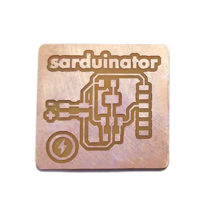
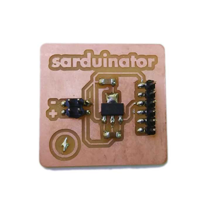
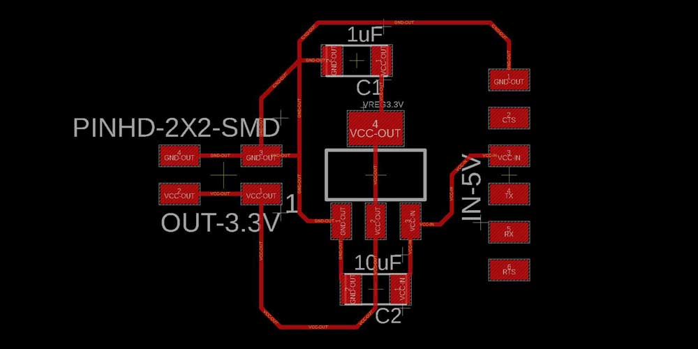
Also if you thought of trying to power up your chip with an Arduino using the 3.3V pin it won't work as this pin is not powerful enough to power the ESP8266, this is why (before knowing about this special FTDI FT232RL) I built an external power supply module, the Sarduinator with a voltage regulator (3.3V 1A) that could provide the 3.3V to the board, but in the end it is not that useful as the chip ESP8266 also needs 3.3V on the logic level TX/RX and with this sarduinator I did I can only provide 3.3V to VCC not to the logic level. In any case here is the module I did and might be useful for my RFID as it also works with 3.3V :
The chip ESP8266 TT-71 has 8 pins, and they are:
STEP 1
First thing you want to do and test is establishing the network connection, and for that you need to
carefully connect your chip to your MCU, and the FTDI (3.3V) or logic level controller.
In my case, as I am using an FTDI FT232RL, plus an external voltage regulator and my own MCU as a programmer, I tried to look for tutorials that explained how to do it, but I have to say what I found so far contradicts a lot on how to do the wiring, and the two tutorials I found most useful and that I've been following are these:
1_ Arduino tutorial
2_ A Beginner's Guide to the ESP8266
I used a breadboard for testing purposes, and to share common pins. This is how I did the wiring
following the tutorials above:
1_ESP8266 RX to TX on the FTDI
2_ESP8266 GND to GND on the FTDI
3_ESP8266 VCC and CH_PD to 3.3V on the FTDI
4_EXP8266 TX to RX on the FTDI
5_Sarduino VCC to external VCC sarduinator
6_Sarduino GND to external GND
7_Sarduino MOSI to TX on the ESP8266
8_Sarduino PB2 to RX on the ESP8266
After doing the wiring, if you are using Arduino IDE, you will have to install several libraries:
1_ESP8266
Arduino tutorial
2_ Copy this url inside Arduino preferences
http://arduino.esp8266.com/stable/package_esp8266com_index.json
http://arduino.esp8266.com/versions/2.4.1/package_esp8266com_index.json
So after installing my libraries, I followed this tutorial and this code
to upload to my chip. Remember to set up the correct profile inside Arduino TOOLS > BOARD >
generic board ESP8266 before uploading the code.
After doing so I should be able to see on my serial monitor the connection status and the IP address,
even after the code was uploaded successfully I can't see this message. So I am in the process of
understanding if there is any wiring problem and how to solve it.
I will try to update this documentation soon once I solve the correct wiring and issues.
_NODE MCU ESP8266
Useful resources about ESP8266
1_link to data sheet of model TT-71 data sheet
_FILES DOWNLOADS
_SARDUINO V3 schematic
_SARDUINO V3 board
_SARDUINO V3 traces
_SARDUINO V3 outlines
_SARDUINO V4 schematic
_SARDUINO V4 board
_SARDUINO V4 traces
_SARDUINO V4 outlines
_SARDUINATOR v.reg schematic
_SARDUINATOR v.reg board
_I2C Master code
_I2C Slave code
_Simple chat