13/ networking and communications
This week we need to design, build, and connect wired or wireless nodes with network or bus addresses:
1. Group I2C communication
2. Making FLAVINO 2.0
3. Making voltage regulation board
4. ESP8266 WiFi Board
5. I2C button control LED
← previous
→ next
⋯ assignment list
🏁/ final project
Group I2C communication
For group assignment this week we tried sending messages between two projects and more using I2C.
I2C (Inter Integrated Circuits) is a serial communication protocol that allows two or more boards to share information through a common clock signal. It has only two wires to share information: Serial Clock (SCL) and Serial Data (SDA).
More detailed explaination on I2C can be found on this circuitdigest page.
We first tried communication between two boards.
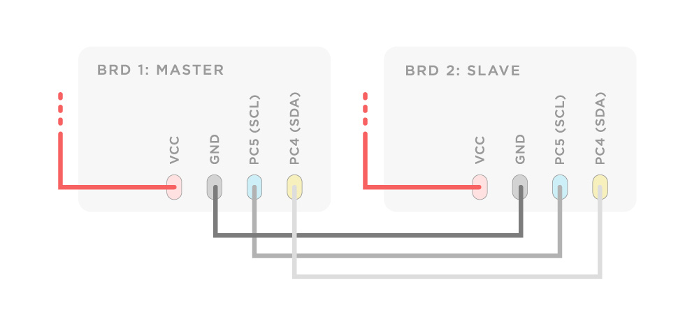
We need to decide one board to be master (send out message) and one to be slave (receive message). Connect the clock/SCL pin and data/SDA pin on the master board to their counterparts on the slave board. Make sure that both boards share a common ground. Each board can get power from its own power source (in our case laptops). In order to enable serial communication, the slave Arduino need to be connected to computer via FTDI cable.

For the test code we used the master_writer and slave_receiver example files under File>Examples>Wire in Arduino IDE. One important thing you need to pay attention to is address number should match in both program in order for the boards to communicate.
Below are some useful commands and their functions copied from the circuitdigest I2C tutorial page.
#include <Wire.h>
The library <Wire.h> should be included in the beginning of the program for using the functions for I2C communication.
Wire.begin(address);
This Initiate the Wire library and join the I2C bus as a master or slave. The 7-bit slave address is optional and if the address is not specified, it joins the bus as a master like this [Wire.begin()].
Wire.read();
This function is used to read a byte that was received from master or slave device, either that was transmitted from a slave device to a master device after a call to requestFrom() or was transmitted from a master to a slave.
Wire.write();
Wire.write(value);
Wire.write(string);
Wire.write(data, length);
This function is used to write data to a slave or master device.
Wire.beginTransmission(address);
This function is used to begin a transmission to the I2C device with the given slave address. Subsequently, build queue of bytes for transmission with the write() function and then transmit them by calling endTransmission() function. 7-bit address of the device is transmitted.
Wire.endTransmission();
This function is used to end a transmission to a slave device that was begun by beginTransmission() and transmits the bytes that were queued by Wire.write().
Wire.onReceive();
This function gets called when a slave device receives a data from a master. Here we can include Wire.read(); function to read the data sent from master.
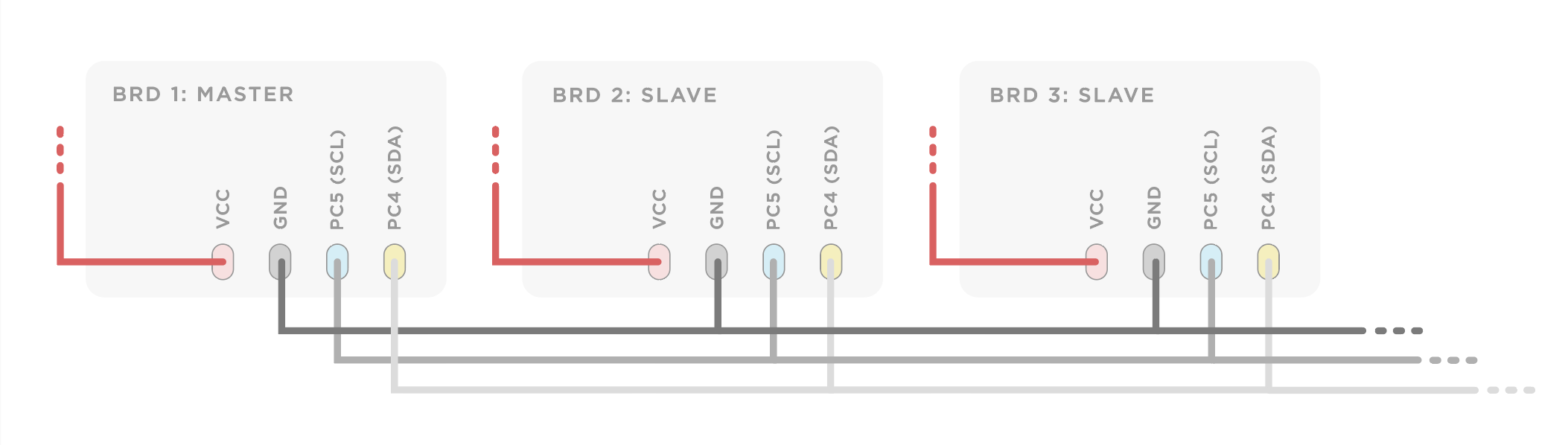
The process above was also applied to multi-board communication.
Below is the code for master writer board to send different messages to slave boards:
// Wire Master Writer
// by Nicholas Zambetti <http://www.zambetti.com>

// Demonstrates use of the Wire library
// Writes data to an I2C/TWI slave device
// Refer to the "Wire Slave Receiver" example for use with this

// Created 29 March 2006

// This example code is in the public domain.


#include <Wire.h>

void setup() {
  Wire.begin(); // join i2c bus (address optional for master)
}

void loop() {
  Wire.beginTransmission(8); // transmit to device #8
  Wire.write("Hello 8");    	// sends five bytes

  Wire.endTransmission();	// stop transmitting

  Wire.beginTransmission(7); // transmit to device #8
  Wire.write("hello 7");    	// sends five bytes

  Wire.endTransmission();	// stop transmitting

  delay(500);
}
And code for slave receiver:
// Wire Slave Receiver
// by Nicholas Zambetti <http://www.zambetti.com>

// Demonstrates use of the Wire library
// Receives data as an I2C/TWI slave device
// Refer to the "Wire Master Writer" example for use with this

// Created 29 March 2006

// This example code is in the public domain.


#include <Wire.h>

void setup() {
  Wire.begin(7);                // join i2c bus with address #7
  Wire.onReceive(receiveEvent); // register event
  Serial.begin(9600);           // start serial for output
}

void loop() {
  delay(100);
}

void receiveEvent() {
  while (1 < Wire.available()) {
    char c = Wire.read(); // receive byte as a character
    Serial.print(c);     // print the character
  }
}
You can also customize the print out lines :D
Below is the told you 120 times code:
// Wire Slave Receiver
// by Nicholas Zambetti <http://www.zambetti.com>

// Demonstrates use of the Wire library
// Receives data as an I2C/TWI slave device
// Refer to the "Wire Master Writer" example for use with this

// Created 29 March 2006

// This example code is in the public domain.


#include <Wire.h>
int x = 0;    // receive byte as an integer

void setup() {
  Wire.begin(8);                // join i2c bus with address #8
  Wire.onReceive(receiveEvent); // register event
  Serial.begin(9600);           // start serial for output
}

void loop() {
  //Wire.onReceive(receiveEvent); // register event
  delay(100);
}

void receiveEvent() {
  Serial.print("I told you ");

  while (Wire.available()) {
    char c = Wire.read();
    Serial.print(c);
    }

      Serial.print(" for ");
      Serial.print(x);
      Serial.println(" times");
x++;
}
We also followed a simple chat program for Arduino tutorial and tried to chat in Serial monitor with SoftwartSerial library.
"The SoftwartSerial library has been developed to allow serial communication on other digital pins of the Arduino, using software to replicate the functionality. It is possible to have multiple software serial ports with speeds up to 115200 bps. A parameter enables inverted signaling for devices which require that protocol."
For it to work you need to open two IDE sessions so that your computer can communicate with both your board serially, and print the results in the serial monitor.
Code below:
/*
  Simple Chat Program

 Receives from the hardware serial,
 sends to hardware & software serial.
 Receives from software serial,
 sends to hardware serial.

 The circuit:
 * RX is A4 (connect to TX of other device)
 * TX is A5 (connect to RX of other device)

 created 16 August 2014
 modified 25 April 2019
 by Flavie Liu
 based on SoftwareSerial example
 */
#include <SoftwareSerial.h>

SoftwareSerial chat(A4, A5); // RX, TX

int text;

void setup()
{
  // open hardware serial, TX = 1, RX = 0
  Serial.begin(9600);
  Serial.println("Starting Chat Program...");
  // set the data rate for the SoftwareSerial port
  chat.begin(9600);
  delay(1000); // delay 1s to stabilize serial ports
  chat.println("Hello World");
}

void loop()
{
  if (chat.available())
    Serial.write(chat.read());

  if (Serial.available())
  {
    Serial.print("Me:\t");
    while (Serial.available())
    {
      text = Serial.read();
      chat.write(text);
      Serial.write(text);
    }
    chat.println();
    Serial.println();
  }

}
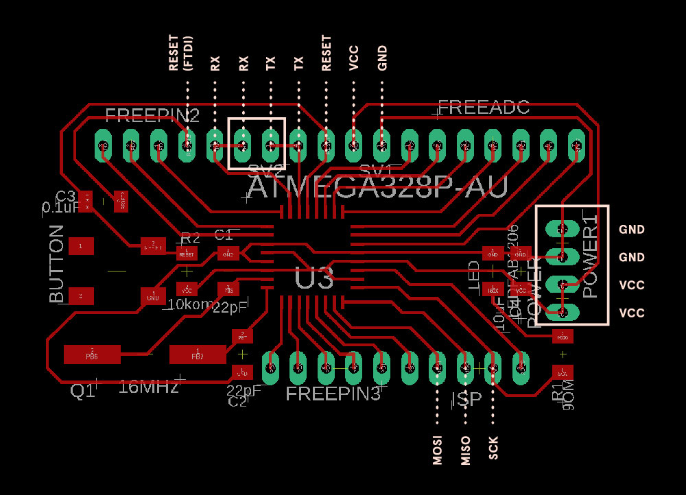
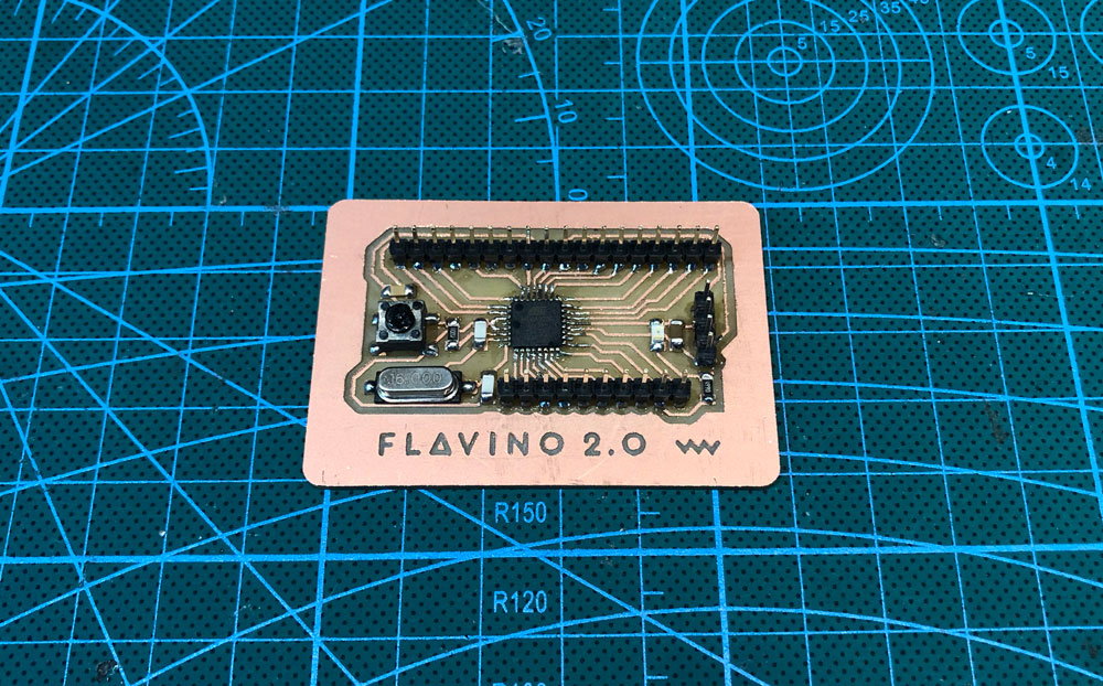
Making FLAVINO 2.0
While using FLAVINO 1.0 for input and output testing, I realize that it will be much more convenient if there were more VCC/GND or RX/TX pins on the board so the board can control several sets of sensors or output devices. So I modified the 1.0 design and started to make an 2.0 board this week.
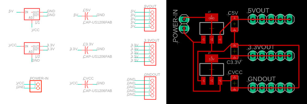
Making voltage regulation board
Since many sensors and modules work at 3.3V level, it is necessary to find a way to output 3.3V power. One way is to use a 3.3V FTDI cable, or to make a voltage regulation board that translate the high level power input to 3.3V and 5V using two different level voltage regulators. I design the board following the power board for satshakit and change the regulators to SMD types we have in our lab.
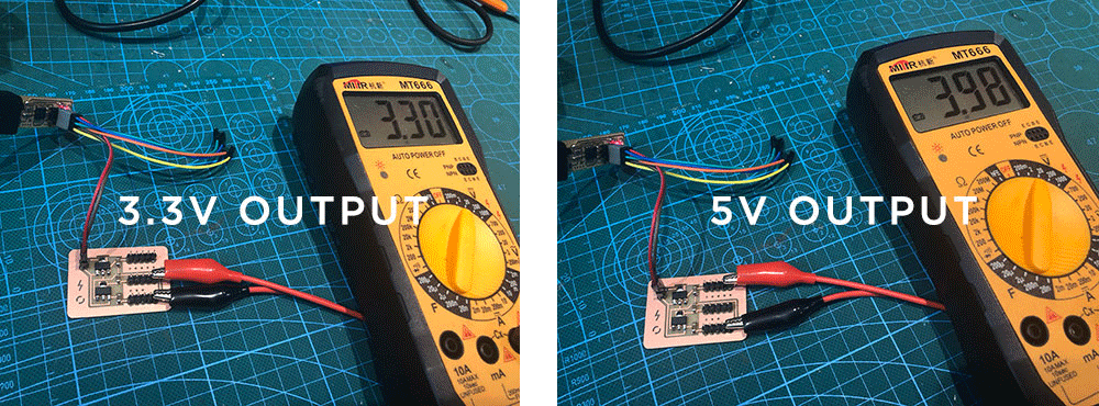
I tested the board with multimeter and it seemed to be outputting the right level of voltage. The input voltage might need to be higher than 5V in order to output 5V.
For modules like ESP8266 wifi and gesture sensor, where not only power but the SCL and SDA pins also need to be at 3.3V level, using this power regulation board is still not enough to make them work :/ I am planning to make a Flavino that runs at 3.3V/8MHz like the arduino mini pro for my next step.
ESP8266 WiFi Board
"ESP8266 is a wifi SOC (system on a chip) produced by Espressif Systems. It is an highly integrated chip designed to provide full internet connectivity in a small package. ESP8266 can be used as an external Wifi module, using the standard AT Command set Firmware by connecting it to any microcontroller using the serial UART, or directly serve as a Wifi-enabled micro controller, by programming a new firmware using the provided SDK."
More detailed intro page for ESP8266 link.
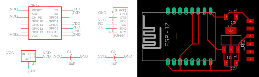
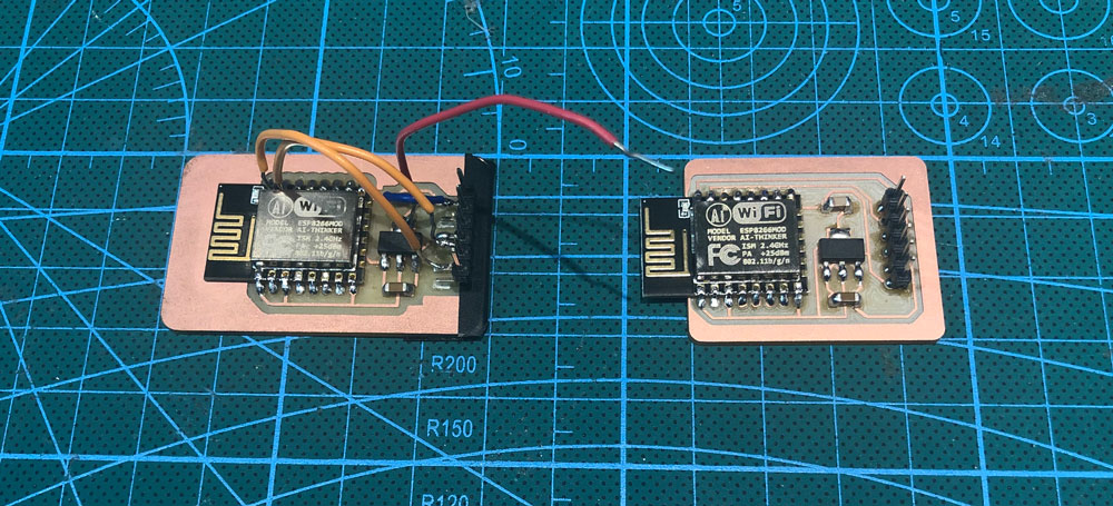
I made the wifi board based on Niel's example. I forgot to connect Rx and Tx pins on my first board (as the board view above), almost destroyed the pin headers while using hot air gun, so I made a second board.
(Updated 04.30.2019)
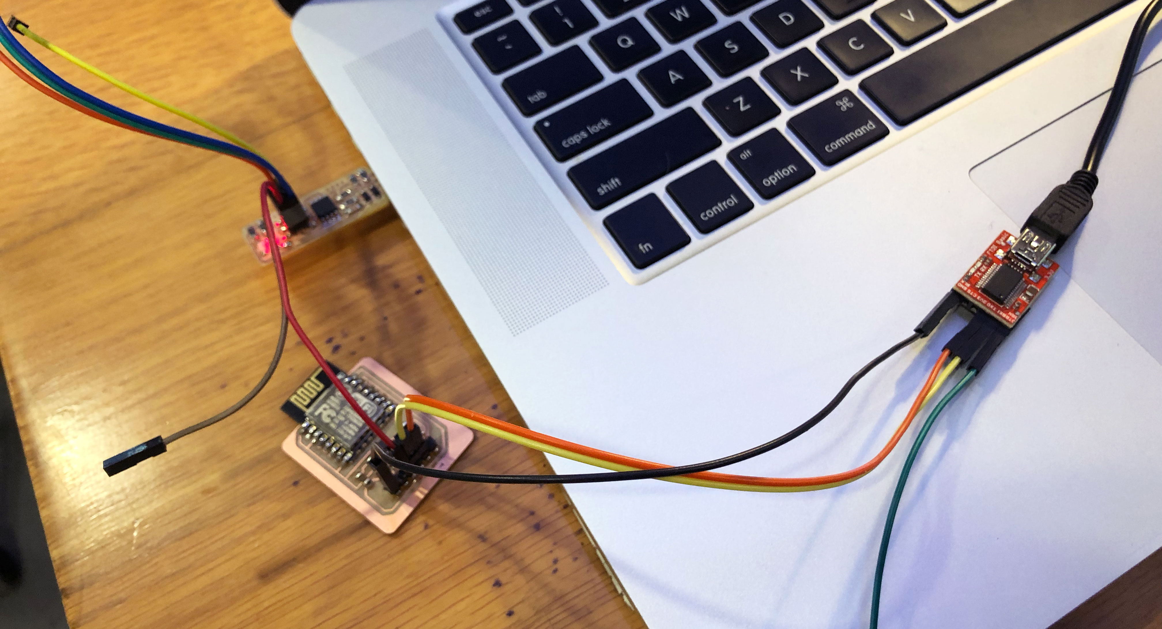
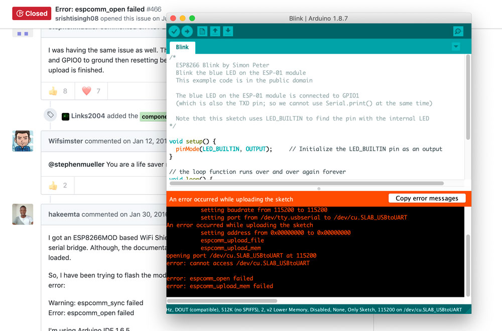
While programming it, I used the FTDI cable that has 3.3V on every pin, but I got problems uploading any program on to the board :/ I tried giving seperate 5V power from my ISP but it still not working. (on the image above, it's better to have power and GND come from the same source.) Since Niel used the original FTDI cable that has 5V on power but 3.3V for signal pins, I wonder if it's my cable's problem or what it can be :/
I2C button control LED
I decided to use I2C communication to control a LED on one board with a button from another board. Here is the instructables tutorial I followed. I used my FLAVINO 1.0 and 2.0, 1.0 as master controlling the button and 2.0 as slave connect to LED. The connection map is as below:
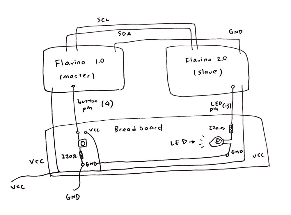

For the coding part, the logic is to have two numbers (1 and 0) representing two button status and send them to slave board once button status changes. Then slave board controls the status of LED base on the number it receives. The communication worked :D
Below is the code for master board:
//Master control button

#include <Wire.h>

int x =0;
const int buttonPin = 4;
int buttonState = 0;

void setup(){
pinMode( buttonPin, INPUT );
Wire.begin();
Serial.begin( 9600 );
}

void loop(){
buttonState = digitalRead( buttonPin );

if ( buttonState == HIGH ){
  x = 1;
}
else{
  x = 0;
}

Wire.beginTransmission(9);
Wire.write(x);
Wire.endTransmission();
delay(200);

}
And the slave board code:
//Slave output LED

#include <Wire.h>

int LED = 13;
int x = 0;

void setup(){
pinMode (LED, OUTPUT);
Wire.begin(9);
Wire.onReceive(receiveEvent);
}

void receiveEvent(){
x = Wire.read();
Wire.endTransmission();
}

void loop(){

if (x == 1) {
  digitalWrite(LED, HIGH);
  delay(200);
}

if (x == 0) {
  digitalWrite(LED, LOW);
  delay(200);
}

}
(Updated 07.09.2019)