_week 16
interface and application programming
This is an interesting week, it is about writing an application that will interface with our
microcontrollers and an input or output device.
In my case I would like to use this exercise for my final project to create an application where a
message is displayed letting me know when my cat goes in/out or a way for me to close or open the door.
Group assignment
Each of us at the lab has tried different interfaces, and programs for this week. This is a list of what each of us has tried and a bit of information of what you can do with each tool:
_Flutter
: is an open source SDK(software developer kit) from GOOGLE. It helps
you build and customize apps for Android and iOs devices (you can customize and choose the device where
the app will run). Apps are written in DART language which uses a C-style syntax
(information source: flutter website and wikipedia). It has something called
emulator which is very useful, it runs the app in a preview of the device you set up to
build the app on. The layout is a widget tree which is acomposition of widgets.
_MIT APP INVENTOR
: is an open source
...
_Processing
: is an open source software sketchbook with and IDE that helps to
visualize coded data. It uses JAVA language and is compatible with Windows, MaciOS and
Linux. In our case, we use it together with Arduino IDE to code and visualize data that comes from a
microcontroller.
_MaxMSP
: is a visual programming
language (like Processing) but for music and multimedia. It is not open source but you can use a 30days
free trial. It is the commonly used developing interactive music performance software.
_Blynk
: is an IoT (Internet of Things) platform that helps you connect your
smartphone to hardware devices, and design apps to be able to control them. It is free but you can pay
for additional features. It is compatible with Arduino so is quite handy to start controlling
input/output devices connected to your arduino compatible PCB.
Individual assignment
During the FAN5 in Seoul, Korea, we meet Fiore Basile, and another classmate (Rico from Kamakura lab) and me asked him some advice for this week's assignment. He mentioned us that we could have a look and try this platform called FLUTTER. I decided to take a look into Flutter for this week's assignment to write my first application that interfaces with my Sarduino and an input/output device.
I am completely new to this, but I thought it could be interesting to check out this platform, so I first started by understanding how it works and then how to run the installation process.
_FLUTTER
Together with the documentation available at flutter website and this tutorial from academind, you can understand better the installation step by step. The installation process differs depending on your operative system. Being a Windows user I have to say that the installation process took me more than half day, as it is not that obvious and simple, but it helped me to understand a bit more how this app developer works.
This is a summary of the important things not to miss for the installation process:
_1 Download SDK for windows, you have to unzip and and create a new directory for "flutter".
_2 Run the .bat file it will promot terminal window, after that is important that you set
the path for the flutter folder directory.
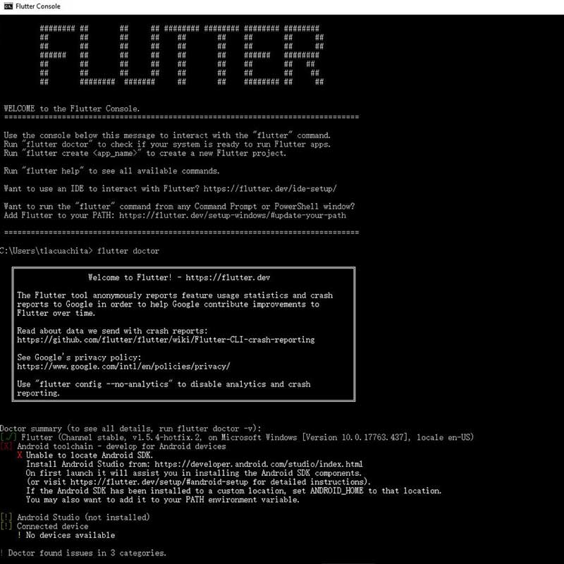
_3 Run flutter doctor inside the directory where you installed flutter, this will give you
a repor of the installation, and you will notice is missing the Android SDK:
_4 Install the Android studio using the .exe file, during the installation activate: ANDROID
VIRTUAL DEVICE, also once you start the installation wizard choose:CUSTOM>(choose
your theme)>Activate Android Virtual Device.
_5 Enable VM emulator
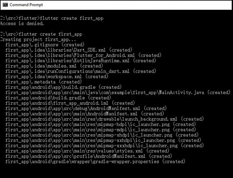
_6 Create a new folder for your new project, you can do it through terminal as well using flutter
create +name of project, for the name of the folder it is important you don't use spaces
or a dash -
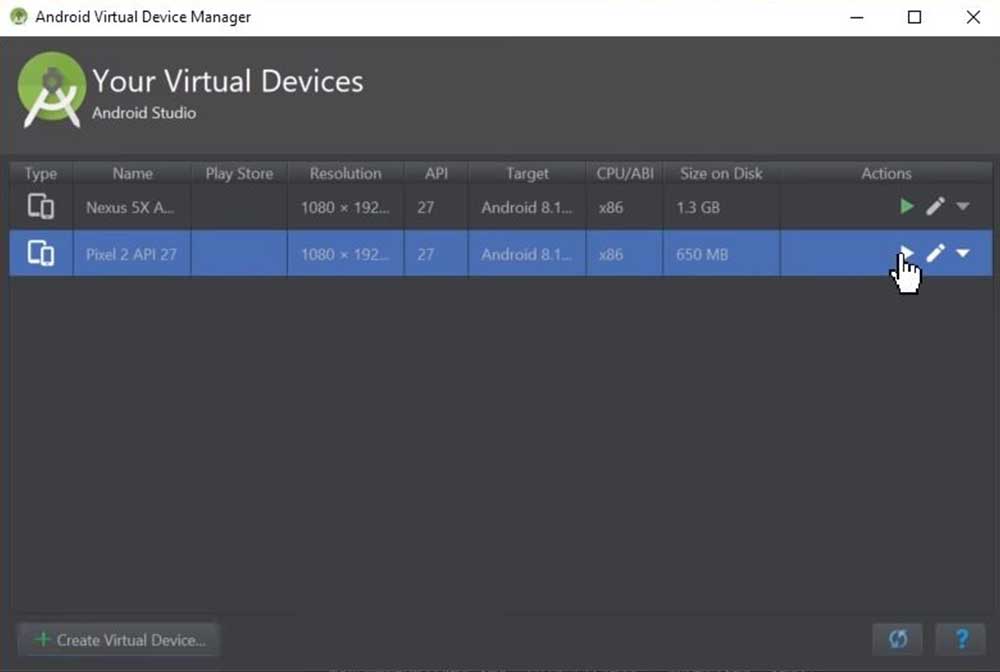
_7 Inside AVD set up the android version you want to use for the emulator. Go to TOOLS>AVD
manager and select the version you need, I used PIXEL 2>OREO 27 (download the
version if is not installed)>choose GRAPHICS-Hardware-GLES 2.0 which for some reason I
couldn't manage to activate the "Hardware emulated performance", so I am using the automatic one.
After doing this set up, you will be able to activate the emulator, which is a virtual representation of
the device you will be working with, quite useful! activate it here:
_8 After this we need to install all the plug ins that are missing, you will see the notice inside
AVD.
_9 Install GOOGLE USB drivers, you can do it inside AVD go toSDK tools> SDK tools> Google USB
driver or directly from the website.
_10 After the installation of the drivers, you should be able to see inside AVD the Android SDK
built for x86 so now you can run the emulator, it will take a bit the first time.

_11 After checking the tutorial and reading the documentation I decided to use VISUAL STUDIO CODE
is an open source IDE. The installation is simple and straight forward.
Like using Arduino IDE, you need to install extensions inside VSC (view>extensions), in our case we need
to install: FLUTTER and Material icon theme this is just for the icons
design.
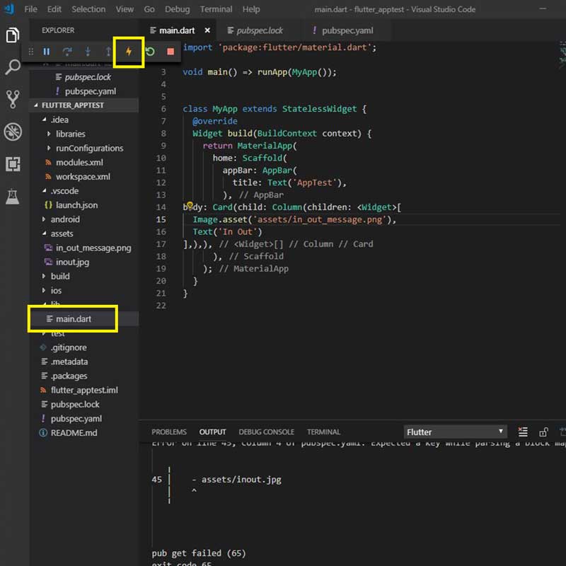
After this long process of installation, you are ready to start coding to create our first app. On the image below I highlighted the which is the hot run button that will run the code into the emulator. The main.dart is the main code of the app, you shouldn't change the name of it, because when you run flutter it will look into the directory for this file and if it has a different name it won't be able to locate ir (like when running make).
_FLUTTER FIRST APP
I followed the tutorial from Academind to build my first app,but I found myself a bit on a dead end, because this tutorial is focused into an app that is a bit far of what I need (which is even more simple) this example is interesting but it uses lots widgets and buttons plus I didn't figure out yet how to integrate into the code an input/output device and control it, something that is not obvious at all.
In any case here are some screenshots of the first app I was building and a short video of the emulator code:

_PROCESSING & ARDUINO IDE
After trying a bit flutter, and trying to work in spirals, like Neil advices us, I decided to try Processing so that I could try using my board and interface with a program with it once for all.
I started checking existing examples to begin with and I found this useful very detailed and clear tutorial from sparkfun that shows and explains 3 examples of processing with Arduino.
FIRST EXAMPLE-arduino to processing
The first example covered is very simple, basically it is what we do in Arduino IDE when using serial monitor to display "Hello World" or any other message, but instead of displaying it in Arduino IDE, it is displayed inside Processing.
_1 I first have to write a code in Arduino to upload into my board, and this is a simple code that runs like this:
void setup()
{
//initialize serial communications at a 9600 baud rate
Serial.begin(9600);
}
void loop()
{
//send 'Hello, world!' over the serial port
Serial.println("Arduino to Processing");
//wait 100 milliseconds so we don't drive ourselves crazy
delay(100);
}
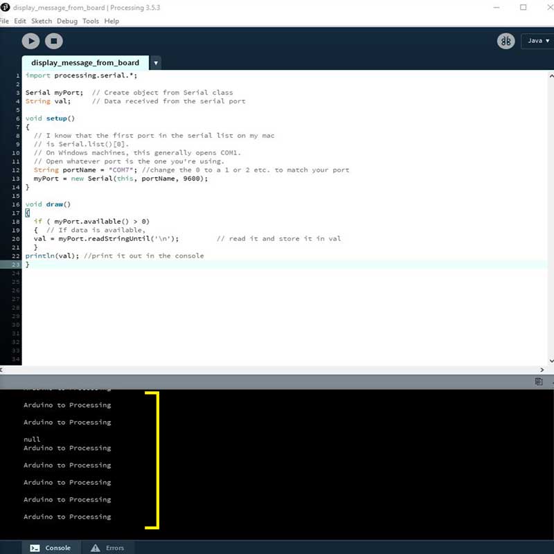
_2 The inside Processing IDE I have to write the code so that it listens what my board is trying to say.
The interface of Processing is very similar to Arduino IDE, the structure of the code works very similar
as well.
As we are establishing a communication with the code uploaded to my board and Processing IDE, is
important no to forget to add the libraries for the serial communication (as we do in Arduino). The code
to write in Processing IDE goes like this:
import processing.serial.*;
Serial myPort; // Create object from Serial class
String val; // Data received from the serial port
void setup()
{
// I know that the first port in the serial list on my mac
// is Serial.list()[0].
// On Windows machines, this generally opens COM1.
// Open whatever port is the one you're using.
String portName = "COM7"; //this setup is for windows port change the # to match your port
myPort = new Serial(this, portName, 9600);
}
void draw()
{
if ( myPort.available() > 0)
{ // If data is available,
val = myPort.readStringUntil('\n'); // read it and store it in val
}
println(val); //print it out in the console
}
IMPORTANT
I ran the code using the same example provided in sparkfun website, but it was not working, and I noticed that was because of the PORT setup. If you are using windows, you need to set up differently the PORT, normally you have COM7/13.. depending on the FTDI cable, you need to set up the port like this:
String portName = "COM7";
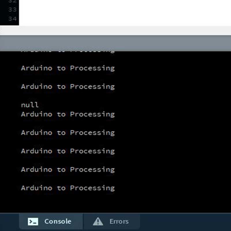
After this if you press RUN inside Processing IDE, you will see the message you uploaded into your board inside Processing console:
SECOND EXAMPLE-processing to arduino
This is a very simple procedure and code but it is amazing the way it works, when I ran it the first iit time was like discovering a new dimension.
Basically what we are doing on this example is to run a code in Processging IDE that will control the LED
pin on my board by simply clicking the Processing canvas.
The way it works is the following:
_1 You have to run this code into Processing IDE, remember to set the correct port (if you use Windows you shall use the COM# syntax)
Once you write this code if you run it you will see a lot of #1 displayed on the console of Processing IDE if you click on the grey canvas, something like this:
_2 After this you have to run the following code in Arduino Ide:
char val; // Data received from the serial port
int ledPin = 13; // Pin on digital pin13=SCK
void setup() {
pinMode(ledPin, OUTPUT); // Set pin as OUTPUT
Serial.begin(9600); // Start serial communication at 9600 bps
}
void loop() {
if (Serial.available())
{ // If data is available to read,
val = Serial.read(); // read it and store it in val
}
if (val == '1')
{ // If 1 was received
digitalWrite(ledPin, HIGH); // turn the LED on
} else {
digitalWrite(ledPin, LOW); // otherwise turn it off
}
delay(10); // Wait 10 milliseconds for next reading
}
IMPORTANT
If you have Processing IDE open together with the canvas and you try to upload a code into Arduino IDE you won't be able as the COM port will be busy and mark an error when running the code. When uploading the code into Arduino you need to have Processing IDE closed.
So, after closing Processing IDE, loading the Arduino code into my board I reopened the code from processing and ran it. And this is how interfacing (if this is a proper term) looks like! pretty cool no?!
_SHAKING HANDS ARDUINO+PROCESSING
The third example is about communicating in both ways, meaning that at the same time Arduino and
Processing are receiving and sending data in both ways.
What we do in this example is to combine the two previous codes, so basically Processing will listen
to the message we load from Arduino IDE and at the same time will be able to control the LED on/off
on the board, meaning that Arduino code has to send a message and receive the code from Processing
simultaneously in order to turn on/off the LED.
The code to upload into Arduino is the following:
char val; // Data received from the serial port
int ledPin = 13; // Set the pin to digital I/O 13
boolean ledState = LOW; //to toggle our LED
void setup()
{
pinMode(ledPin, OUTPUT); // Set pin as OUTPUT
//initialize serial communications at a 9600 baud rate
Serial.begin(9600);
establishContact(); // send a byte to establish contact until receiver responds
}
void loop()
{
if (Serial.available() > 0) { // If data is available to read,
val = Serial.read(); // read it and store it in val
if(val == '1') //if we get a 1
{
ledState = !ledState; //flip the ledState
digitalWrite(ledPin, ledState);
}
delay(100);
}
else {
Serial.println("Hello am processing it!"); //send back a message back
delay(50);
}
}
void establishContact() {
while (Serial.available() <= 0) { Serial.println("A"); // send a capital A delay(300); } }
After uploading the code to my board, I have to run the code inside Processing:
import processing.serial.*; //import the Serial library
Serial myPort; //the Serial port object
String val;
// since we're doing serial handshaking,
// we need to check if we've heard from the microcontroller
boolean firstContact = false;
void setup() {
size(400, 400); //make our canvas 200 x 200 pixels big
// initialize your serial port and set the baud rate to 9600
String portName = "COM7"; //this setup is for windows port change the # to match your port
myPort = new Serial(this, portName, 9600);
myPort.bufferUntil('\n');
}
void draw() {
//we can leave the draw method empty,
//because all our programming happens in the serialEvent (see below)
}
void serialEvent( Serial myPort) {
//put the incoming data into a String -
//the '\n' is our end delimiter indicating the end of a complete packet
val = myPort.readStringUntil('\n');
//make sure our data isn't empty before continuing
if (val != null) {
//trim whitespace and formatting characters (like carriage return)
val = trim(val);
println(val);
//look for our 'A' string to start the handshake
//if it's there, clear the buffer, and send a request for data
if (firstContact == false) {
if (val.equals("A")) {
myPort.clear();
firstContact = true;
myPort.write("A");
println("contact");
}
}
else { //if we've already established contact, keep getting and parsing data
println(val);
if (mousePressed == true)
{ //if we clicked in the window
myPort.write('1'); //send a 1
println("1");
}
// when you've parsed the data you have, ask for more:
myPort.write("A");
}
}
}
After running the code inside processing what will happen is that whenever I click inside the grey canvas I am turning on/off the LED and receiving the message I wrote inside Arduino code.
I wanted to personalize a bit this grey canvas so I started checking some tutorials about processing.
I found out that to add text on your canvas you first need to check what are the available fonts in
your systme, for that you need to run the following code inside Processing IDE, which will show you
on the console the family fonts names you can use (source: Processing).
This is the code to run and how it will display the console the names:
size(200, 200);
String[] fontList = PFont.list();
printArray(fontList);
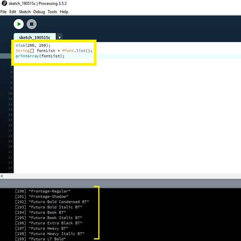
This will show you all the available fonts so you can add them into your code.
I also found a useful library called ControlP5, which is a graphical User interface (GUI) so you can add buttons, or other graphics in your programming.
APP DESIGN with MIT APP INVENTOR
For my final project I wanted to have an app where I could control the access of Mirru to the house.
So using MIT APP INVENTOR and a bluetooth module (together with my mcu and sensors), I
designed an app where you can close and open the lock of the door.
All the documentation on how I built the app interface and how to make your own app from scratch is
inside stage 5 (app design)
_DOWNLOAD FILES
Here you can find the files I used during this week:
_LED onoff controlled on processing
_display
message
_shaking hands processing led hello
_display message from board
_processing to arduino LED onoff
_processing to arduino led on off fancy button
_processing to arduino led on off fancy button
_text background simple