11. Input devices
This week I will generate an Ultrasonic sensor.
Group assignment
In this case all the remote students have been together testing different boards with a Oscilloscope for the analogic waves, and a photometer to check the digital ones. Our own one is the DS212 Mini Oscilloscope. We have checked the manual of how does it works here:
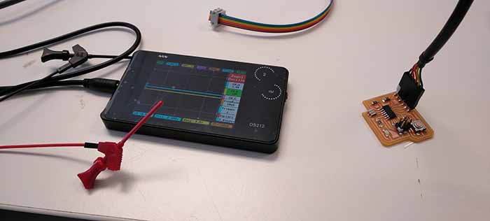
With these little tweezers we were choosing the paths to check it.
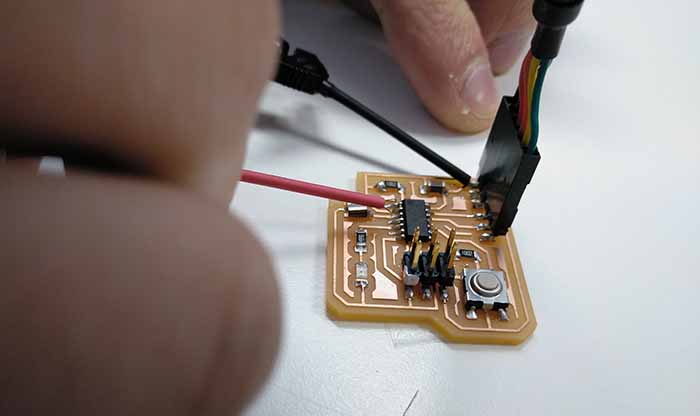
The problem with it is that this oscilloscope is very sensitive and we were not capable to adjust the screen to observe good the different waves. So we changed it for another one DSO SHEEL, that works the same as the other.
Here is the analogic signal with the “Hello board”
Here is the digital signal with the “photometer board”
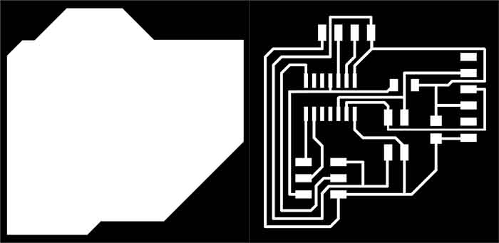
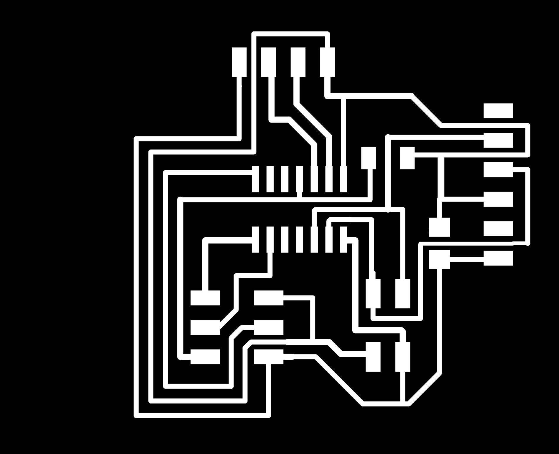
Generating the model in Eagle
As we did in assignment 7 we have to redo a PCB to achieve that our input device works.
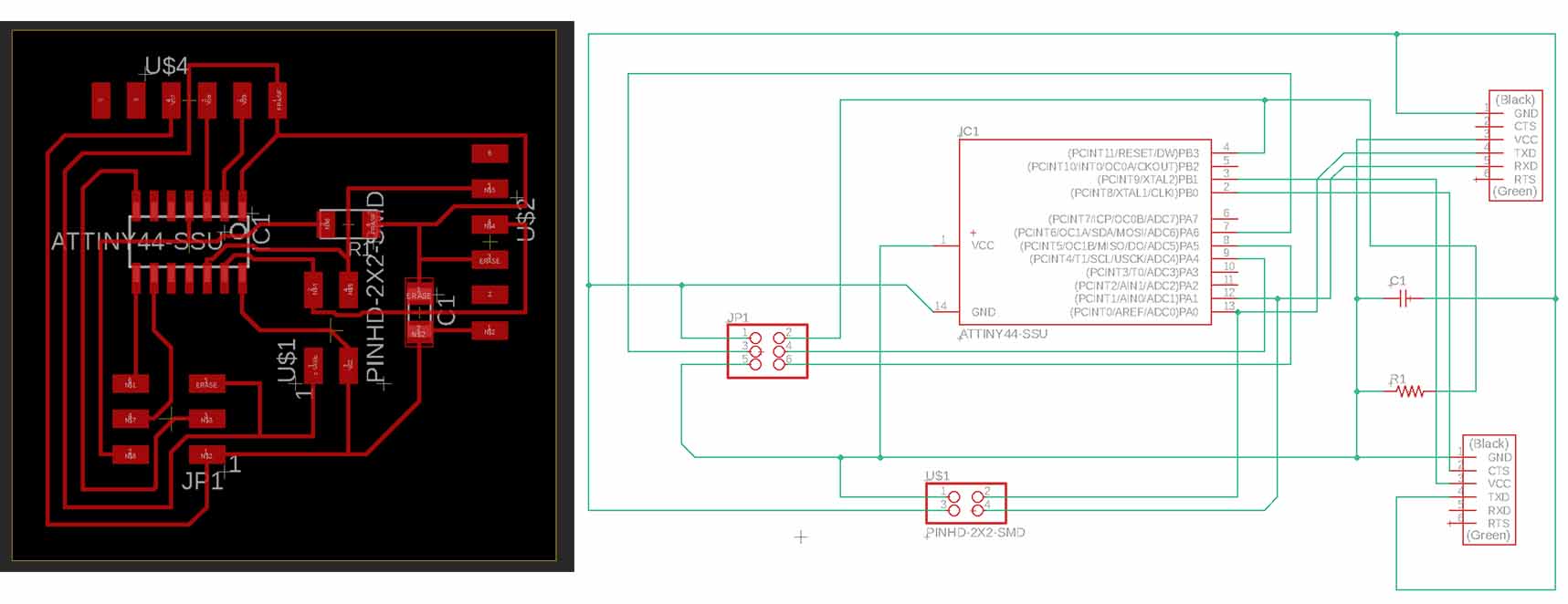
Our instructor Nuria, suggest to inspire ourselves in one old student, Szilard A. Kados that redo this board to combine it with the next assignment of communications.
Another thing to need to now is that I couldn´t find the resonator reference in the Fab library of EAGLE, so I asked what my college did, and Elena Cardiel used a FTDI module to adapt a resonator. I will erase the extra pines in photoshop. Just for learning, because I don´t know how to manage Eagle software, I did Elena´s one.
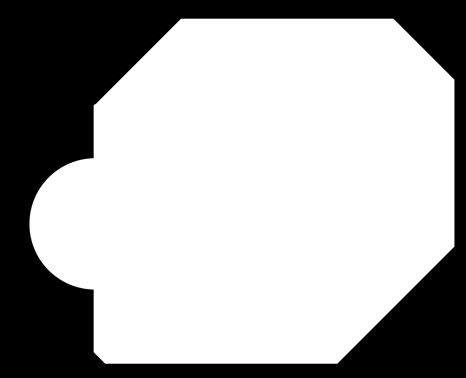
Milling the boards
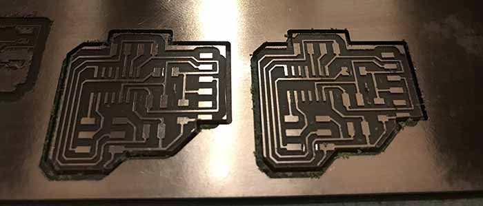
As we did in the last assignment assignment performing the milling machine, placing the base and fixed it, and calibrate Z axis and Origin.
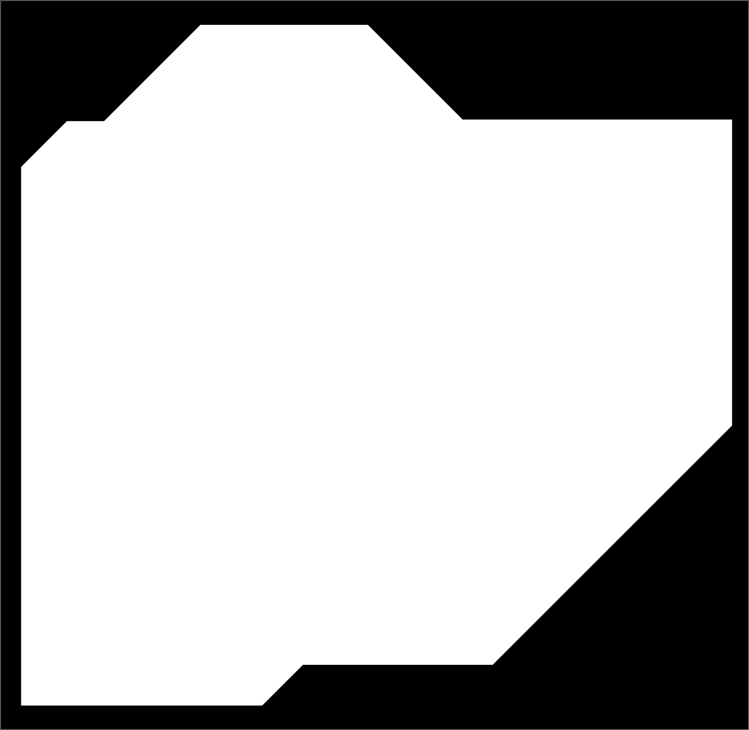
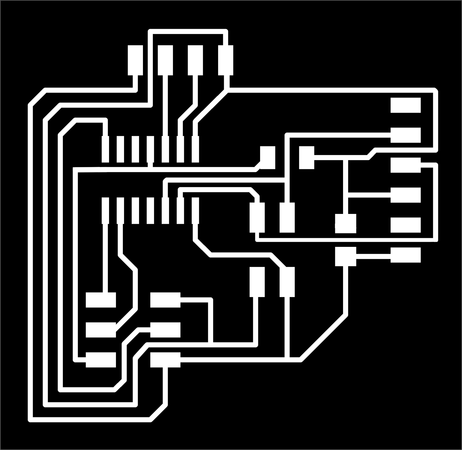
After that follow the steps to generate the traces for the milling machine and you will obtain something like this:
How I have to do my own PCB I repeat the same process but this time learning how to do in Eagle software and here are my files self-doing and different from my partner:
If anyone could suspect of my work, I did a third one because as our tutor Nuria told me, it is very similar to my partner Elena. Of course I have said, I am learning because it is my first time milling copper boards, opening Eagle program, design electronic circuits, etc. I have design by my own hand every file but I don´t want to fail this practice so I have redone my pcb, with the same components, because I am not engineer and I don´t have a 4 years degree designing pcbs, just few weeks so I can´t not assume the big knowledge that I must need to change so much my pcb.
But it´s true that I could improve it with a handle to manipulate it better when you move in the air to get data.
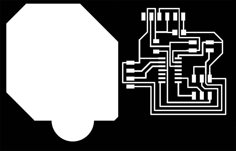
So here you can download the new ones:
Generating PCB
When we will have all the ingredients, its the moment to solder it all.
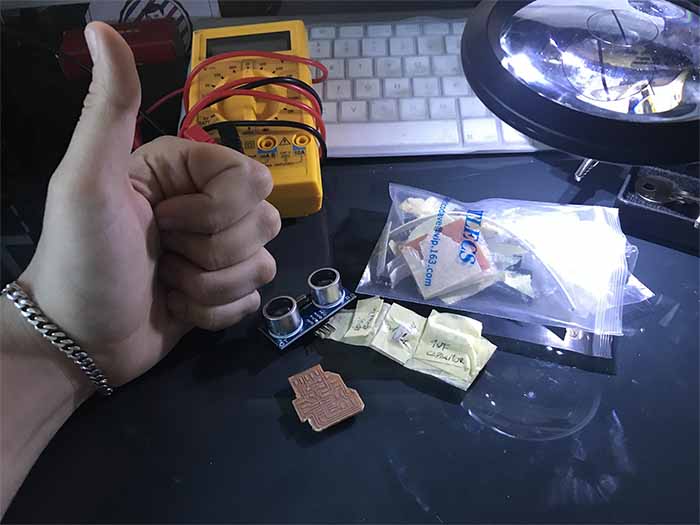
We will have the following components:
- 1 x Ultrasonic sensor HC-SR04
- 1 x ATtiny44
- 1 x 10kΩ resistors
- 1 x 1uF capacitor
- 1 x FTDI Connector
- 1 x 2x3 pin header
- 1 x 2x2 pin header
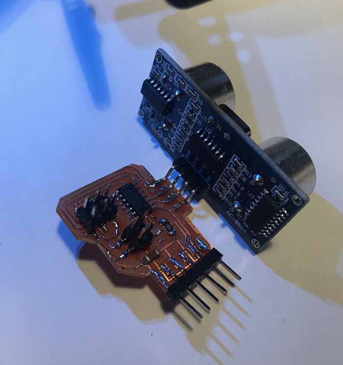
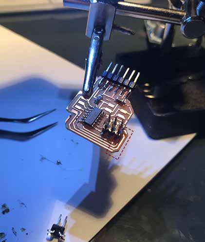
This is the result of my first PCB:
When I connected all the wires to press “burn Bootloader” I had an error in Arduino
avrdude: Error: Could not find USBtiny device (0x2341/0x49)
Error while burning bootloader.
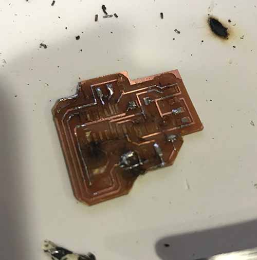
After a lot of time checking what was wrong I discovered this! The out traces was bad designed and it cut inner traces so it couldn´t communicate with nothing…
I had to desolder all the components and redesign the PCB and milling again…
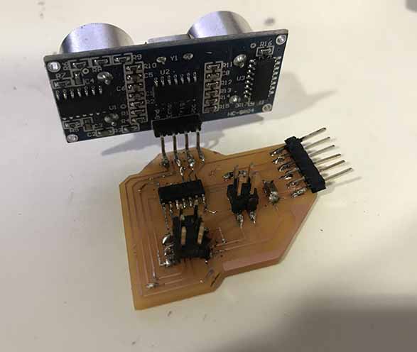
And finally here is the new PCB
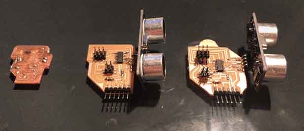
And as I have explain you I have done this practice with more than one sensor pcb so This is the final result of my last Ultrasonic pcb with handler:
Let´s programming
Now I try to connect everything again and burn Bootloader and it this time I achieved the glory!

Here you can find the program to turn on the Ultrasonic device I have redo after see my partners .Ino :
I have explained every step I did inside the sketch from Arduino.
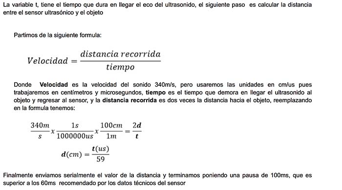
But actually I created "const" variables; adjusting the Baudrate;
Generating a Delay that will print every measure it takes;
print "cm" as the units it takes;
Later those variables need to carry a programing where every pulse of the ultrasonic sensor will delay, receive and write with a conversion each information.
Of course I have used this formula and it works accuracy so I didn´t need to calibrate the sensor
You will find this tutorial here:
And here a demo of how it works

Este obra está bajo una licencia de Creative Commons Reconocimiento-NoComercial-CompartirIgual 4.0 Internacional.