11. Input devices
For this weeks assignment I Patterned my board off the switch design.
Research
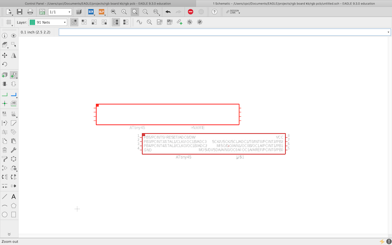
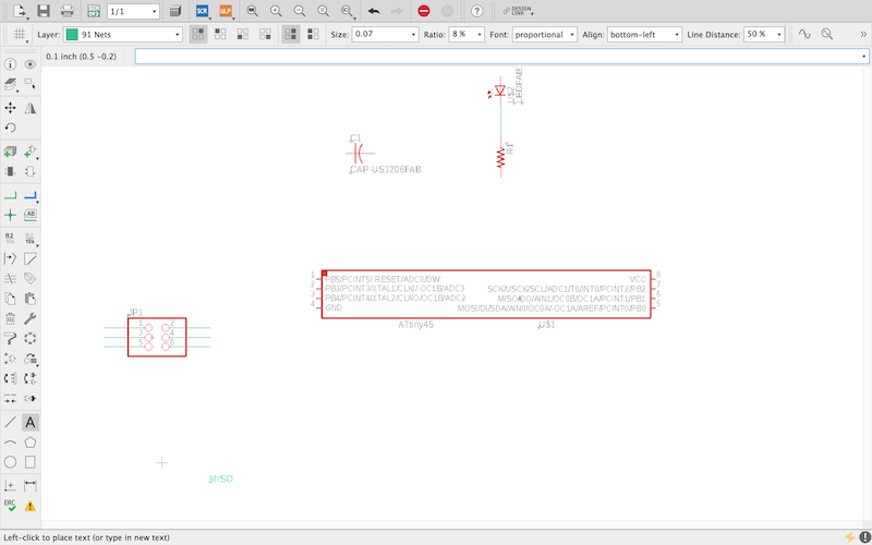 What I did was I sketched out the schematic in Eagle. Then altered the traces for the board made sure that everything was accurate according to the Board that I selected. It took me a while to figure out how to find the trace patterns. Then paid attention to how each pinhead or soldered to certain trays on the board.
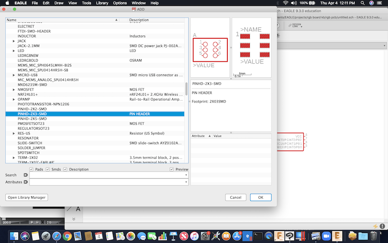
I then attach them to the pieces I pulled from the fab library file.I had to import the file from Github.Once I put all the components together on the schematic I created the board.
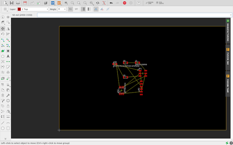
Once I upload of the board components are used the auto Router to afterOriented the components in a certain way. Once the auto router was done I had to select the design that had no vias.
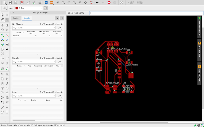
After I got the traces where I wanted them. I saved the file and then exported it as a PNG to my desktop. From there I cropped the PNG using clip studio. Then created a outline by tracing the outer parametersOf the layout. After that I filled the negative space with white. That created the outline. From there I Uploaded the files to mods. And converted the file to an Rml.
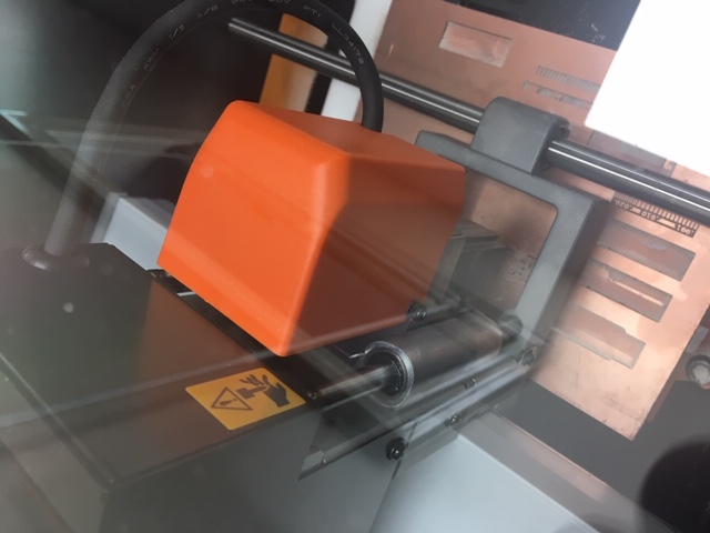
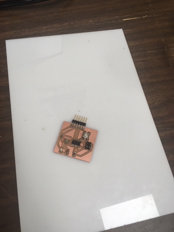
I then set up the milling machine , Mill the board, and added the components.
Useful links
Code Example
Use the three backticks to separate code.
// the setup function runs once when you press reset or power the board
void setup() {
  // initialize digital pin LED_BUILTIN as an output.
  pinMode(LED_BUILTIN, OUTPUT);
}

// the loop function runs over and over again forever
void loop() {
  digitalWrite(LED_BUILTIN, HIGH);   // turn the LED on (HIGH is the voltage level)
  delay(1000);                       // wait for a second
  digitalWrite(LED_BUILTIN, LOW);    // turn the LED off by making the voltage LOW
  delay(1000);                       // wait for a second
}
Gallery

Video
From Vimeo
Sound Waves from George Gally (Radarboy) on Vimeo.