mechanical design, machine design
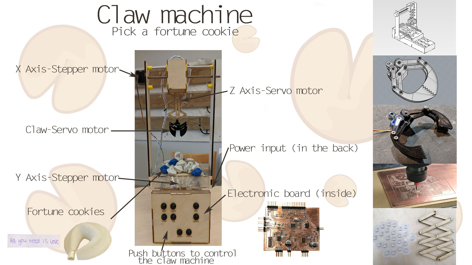
Intro to a claw machine
Inspiration
The idea began with this video of a claw machine. We thought that a claw machine is simple, but shows basic mechanisms for a machine which contains XYZ movement.
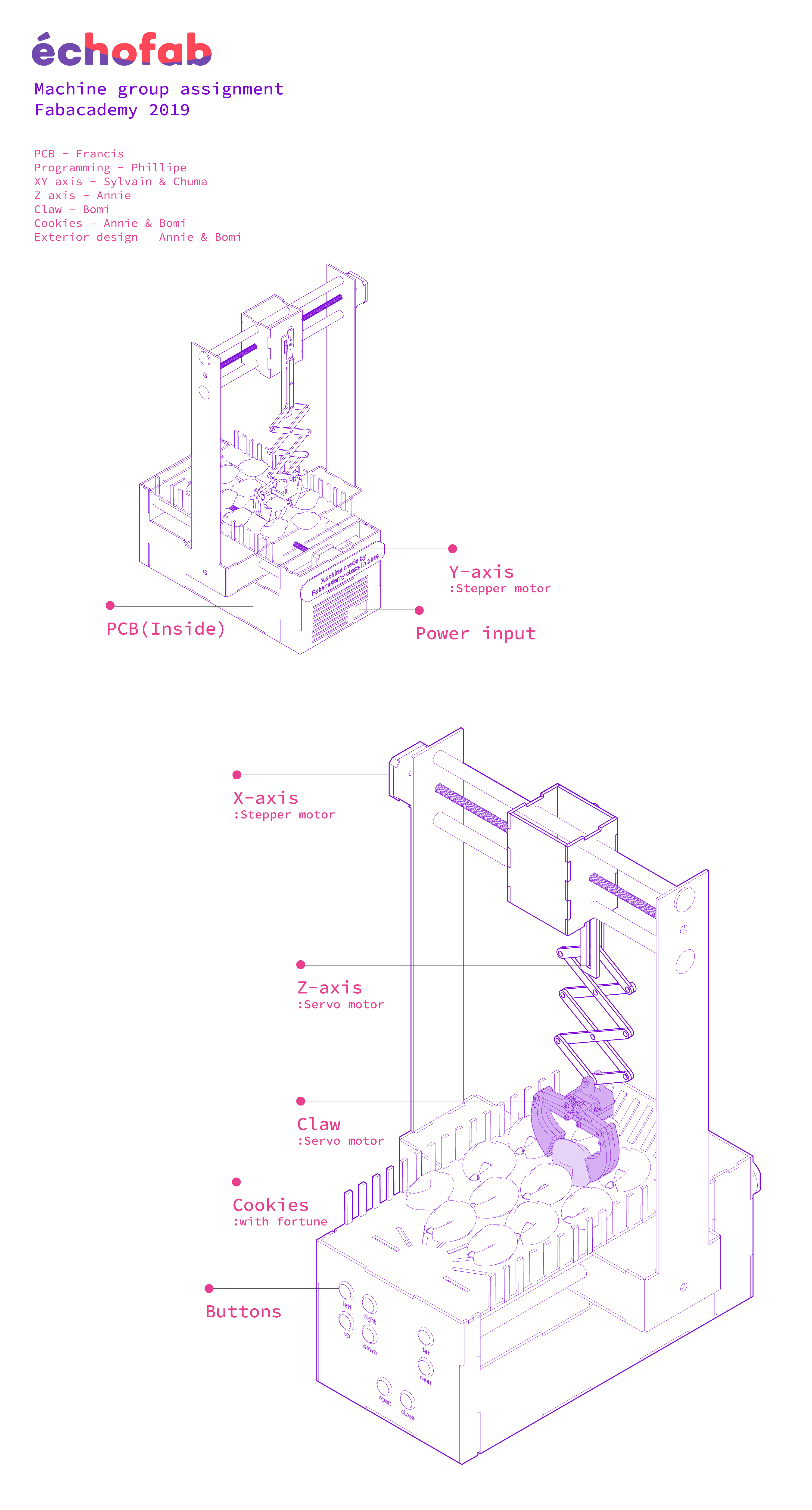
We designed a claw machine with fortune cookies that contain meaningful messages that could make people smile. All the machines are normally fully controlled by a human. We wanted to put the randomness in controlling so that the machine could have uncertainty and mystery of giving a fortune cookie when people play with the machine. To design a machine, we divided our roles into individual tasks like below. Then, assembled it together.
You can check how things are done in individual parts with more details on their website.
Sylvain Brunet - X-Y Axis and assemblyChukwuma Asuzu - X-Y Axis
Francis Lance - electronic hardware and assembly
Annie Ferlatte - Z axis and assembly
Bomi Doh - Claw and assembly
Philippe Libioulle - Software and assembly
#1 - x,y axes
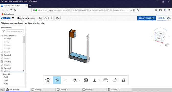
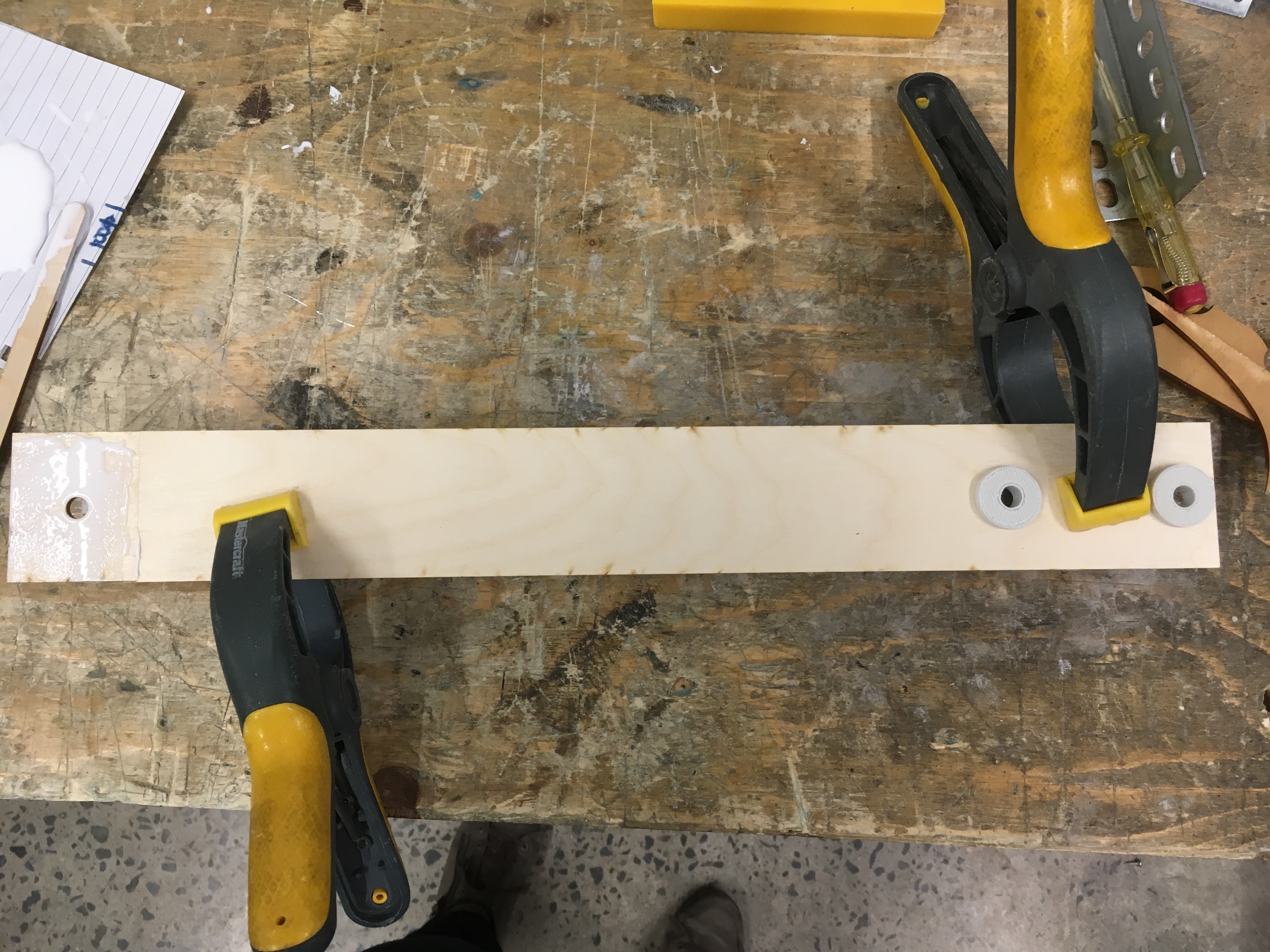
The x,y axes created with the similar principle as our CNC machine in échoFab lab. A frame can move and be guided by 2 rods. After 3D modeling and the fabricating by the laser cutter, we only need some glue and screws to assemble them like a puzzle (see the section of assembling the machine) Also, to help the guidance and hold the metal rods, Sylvain had the greatest idea of creating a little hardware 3D printed pieces(Yellow part) to complete the XY axes.
You can refer to Sylvain Brunet site for more details about that part.
#2 - The container
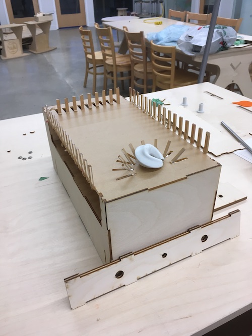
Design around the axes, the design of the machine followed the function of the previous axes. The design was considered to be delicate and light, we decide to eliminate the entire box around the mechanism and only do the table of the claw machine and the electronic integration. With plywood and acrylic, this container design has a little Asian taste because of the fortune cookie history, we band the acrylic to hold all these fortune cookies.
You can refer to Annie Ferlatte site for more details about that part.
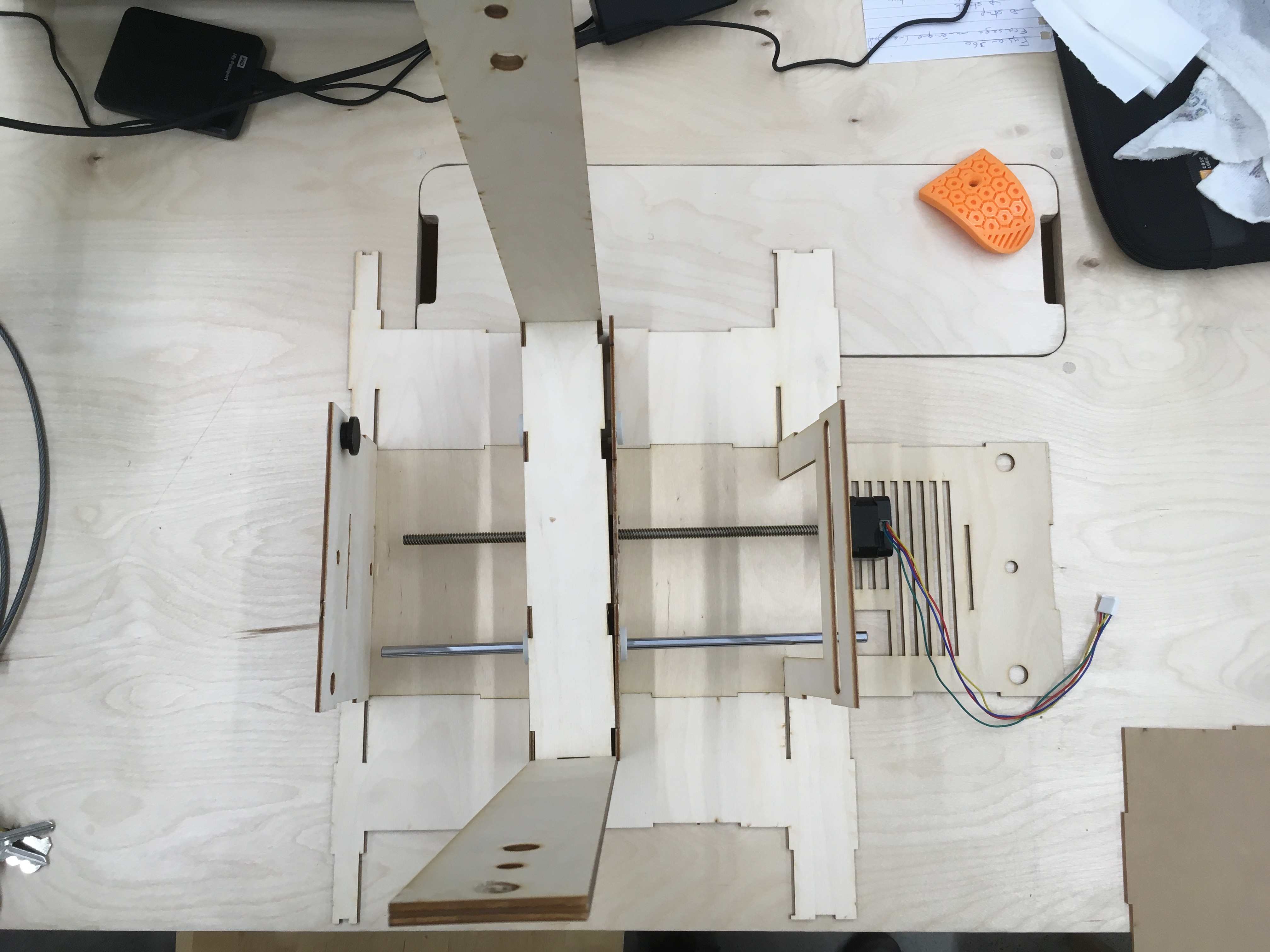
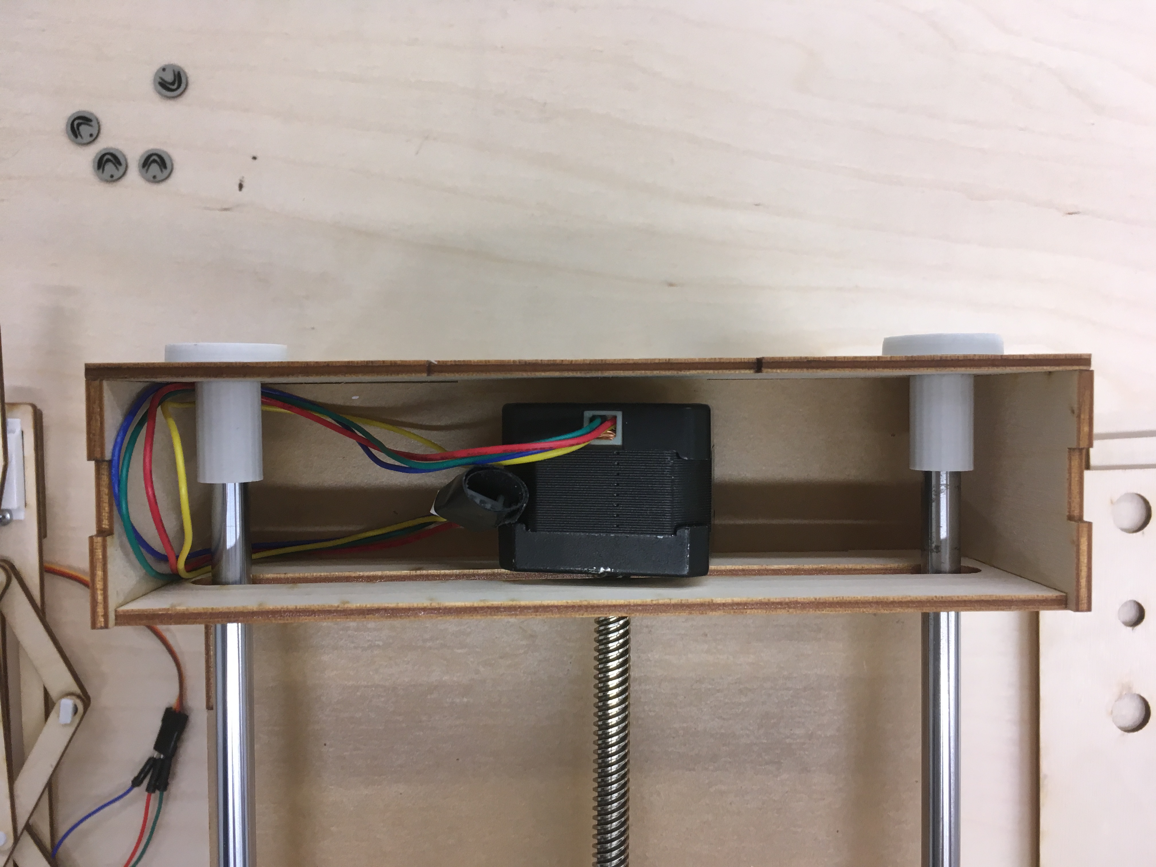
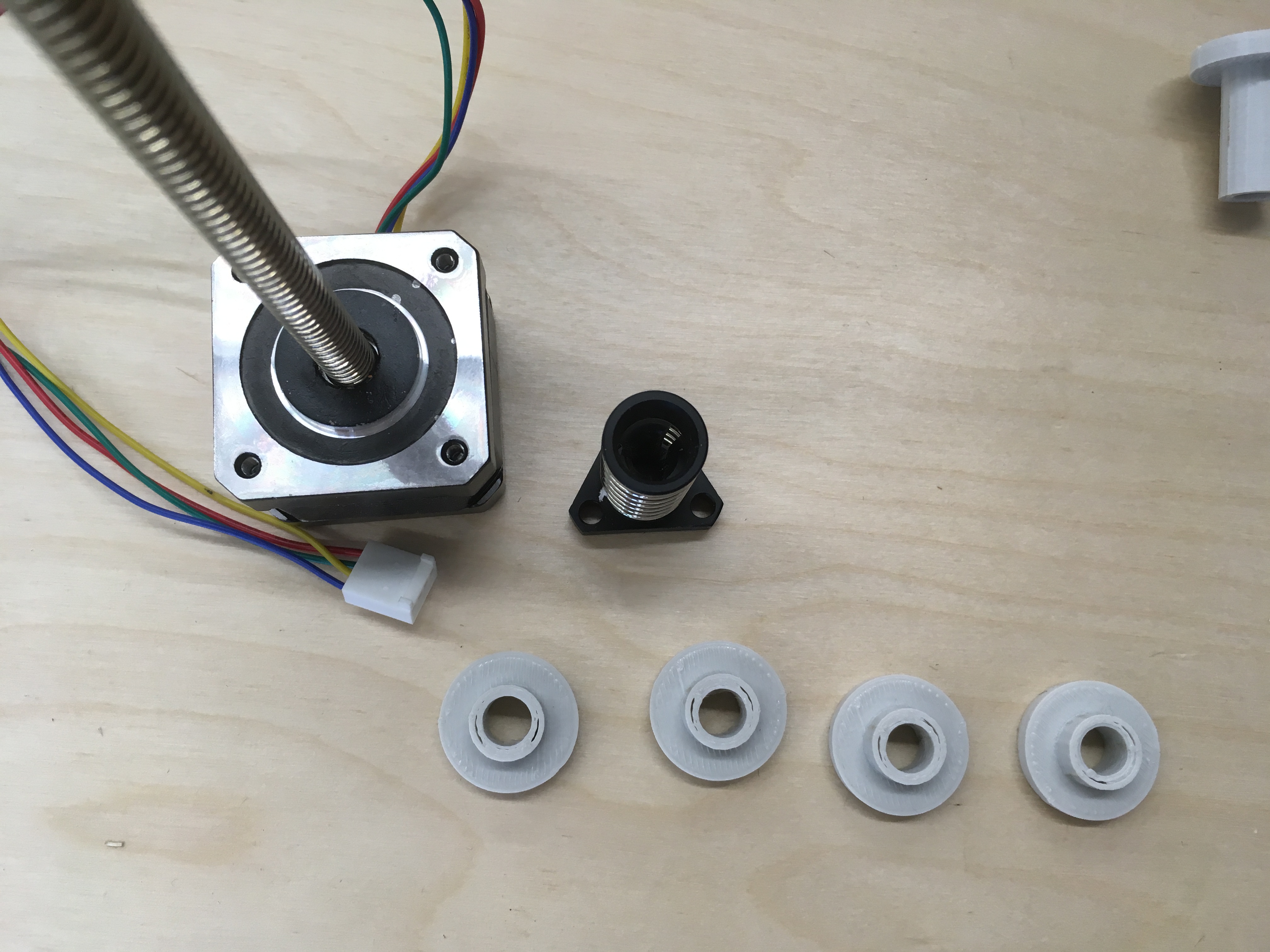
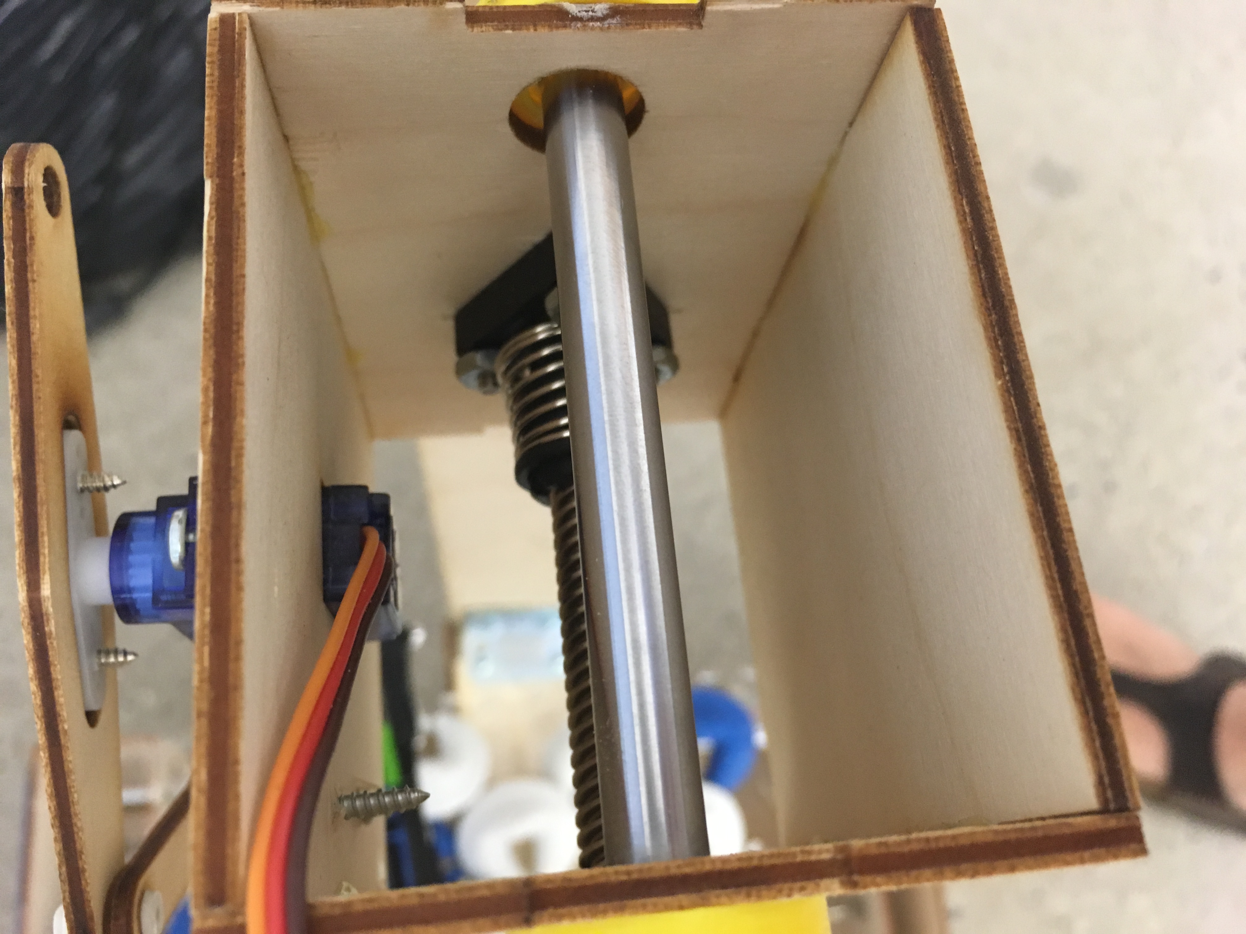
#3 - Z axis
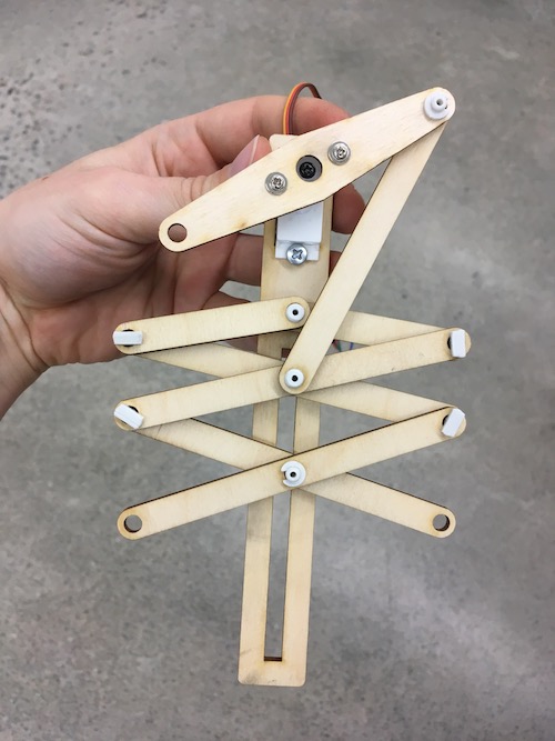
The z axis was designed with 3D printed snap fit components and laser cut plywood for the main structure. The mechanism is actuated by a servo motor. The z axis is all about changing a circular motion into linear motion.
You can refer to Annie Ferlatte site for more details about that part.
#4 - Claw
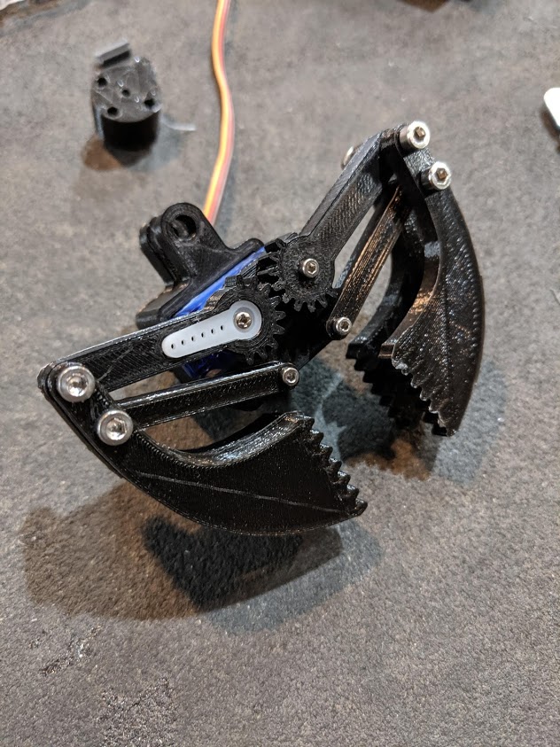
The claw had a few different versions. The first one was an inflatable claw made with ecoflex 0030 by an air pump. The second one was 3D printed flexible claw, but this one was a bit weighty for our Z axis. The last one has two 3D printed claws on both sides to help holding the cookie. The weight was a vital consideration while designing a claw because of the capacity of the servo motor. Also working degree of servo was one of must-check lists.
You can refer to
Bomi Doh site for more details about that part.
#5 - Control pad
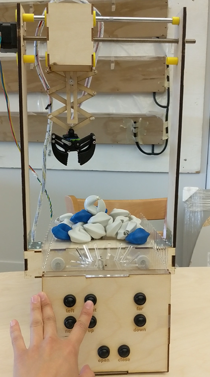
The control pad is in front of the claw machine. The initial design was a bit different and had a better affordance than the final design. However, to go with container design and to make less waste, the control pad was designed with one plywood board which was the design that we didn't have to change the current container shape.
You can refer to
Bomi Doh site for more details about that part.
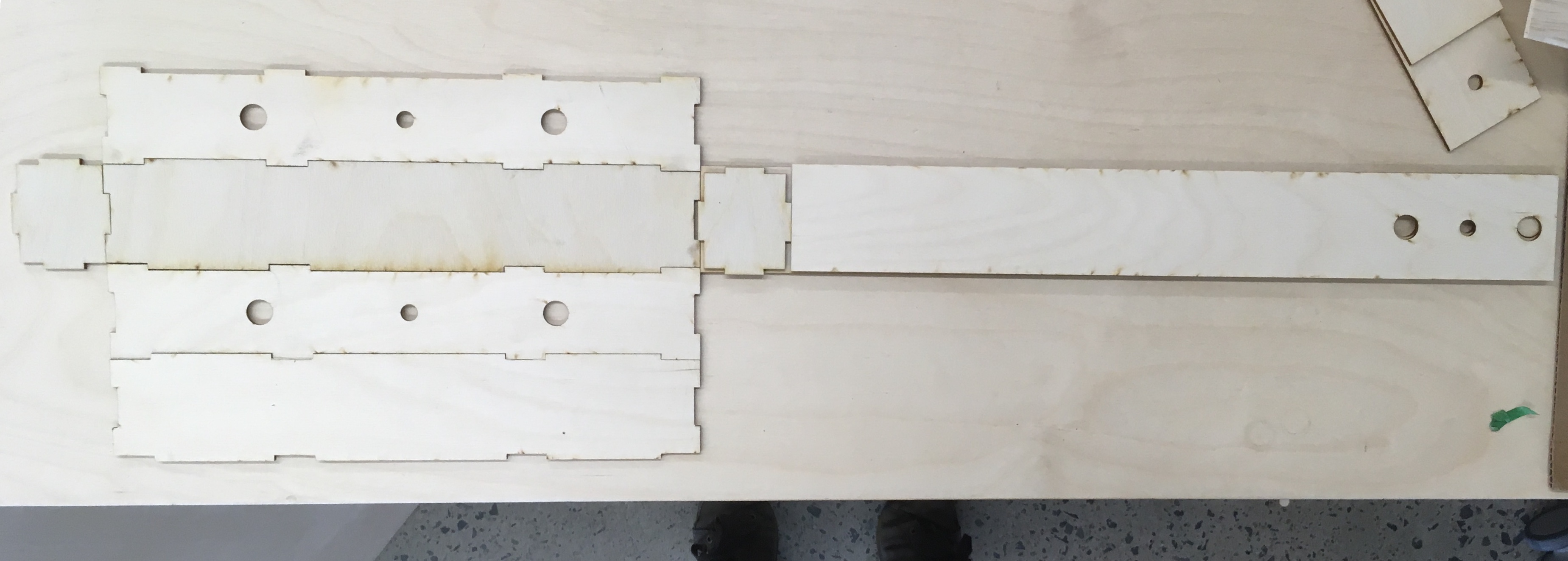
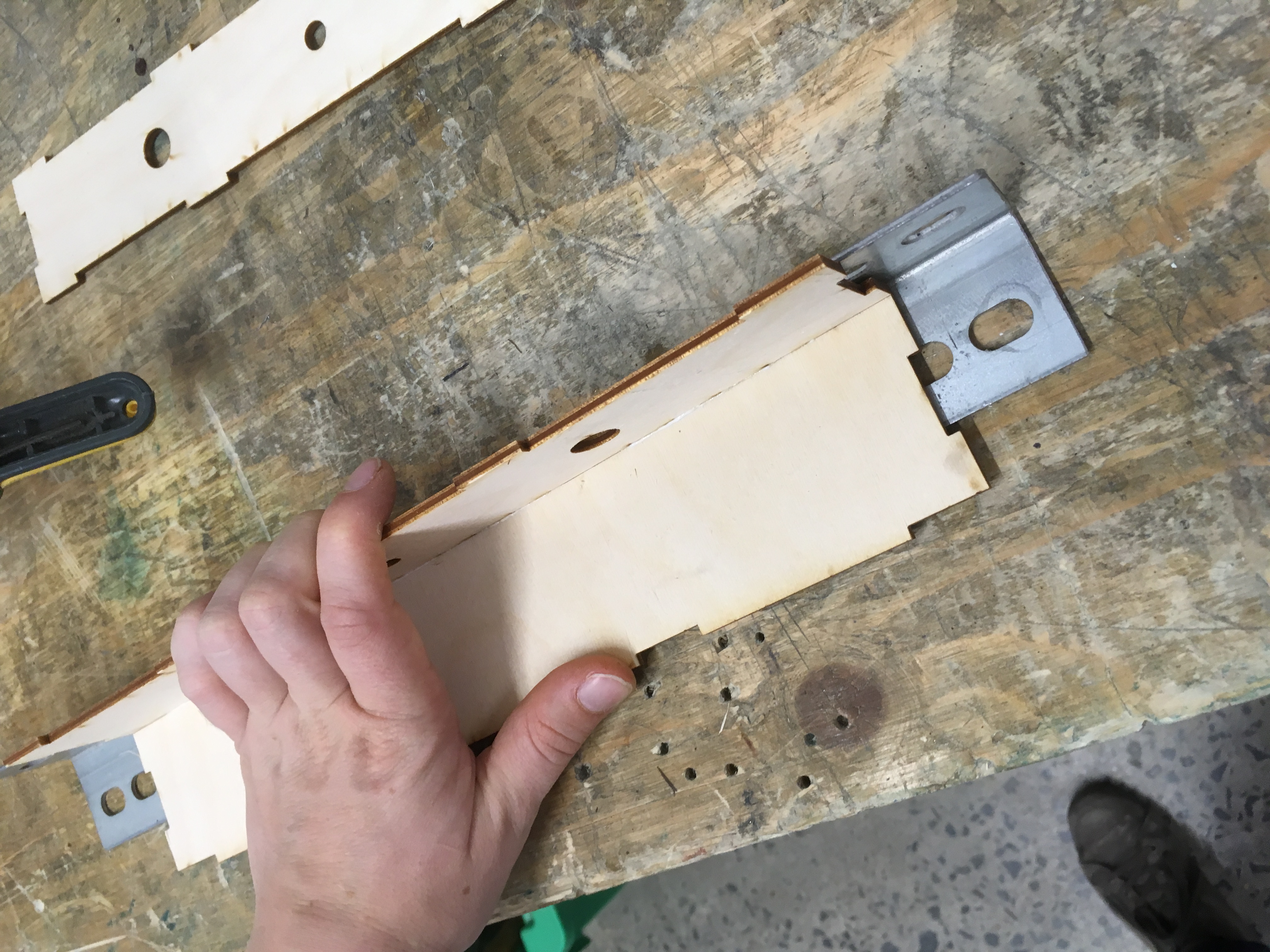
#6 - Assembling the machine
For the assembling, Our team gathered to assemble all parts together. We began by gluing everything and making sure that the boxes are sturdy enough to make the rods move smoothly. Then, soldered the buttons and protected the connection with a heatshrink tube. Finally, we tested the tolerance in each mechanical parts for 3 degrees of freedom and connected everything to the electronic board to see if it worked. It was a really productive day.

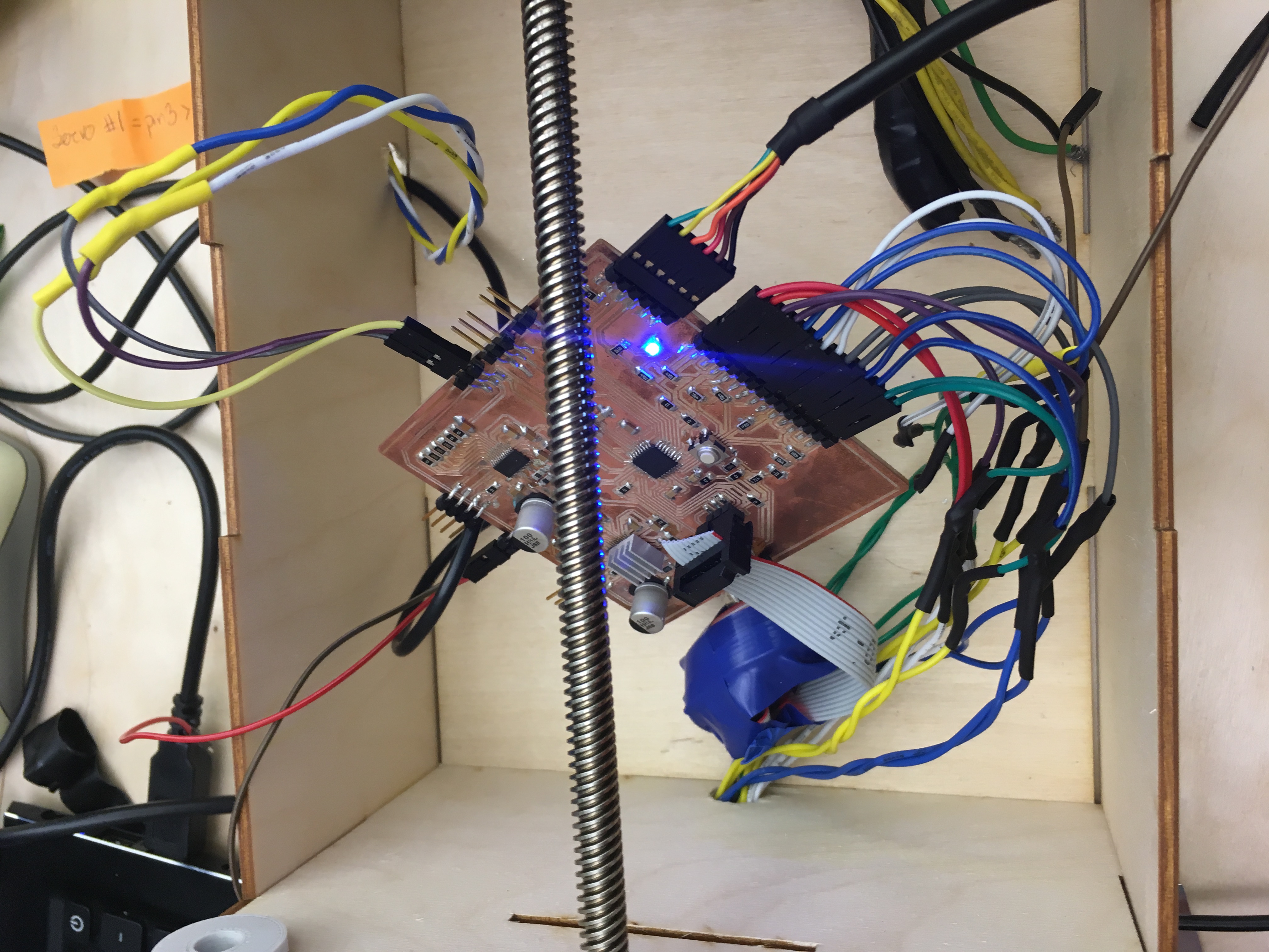
#7 - Electronic hardware
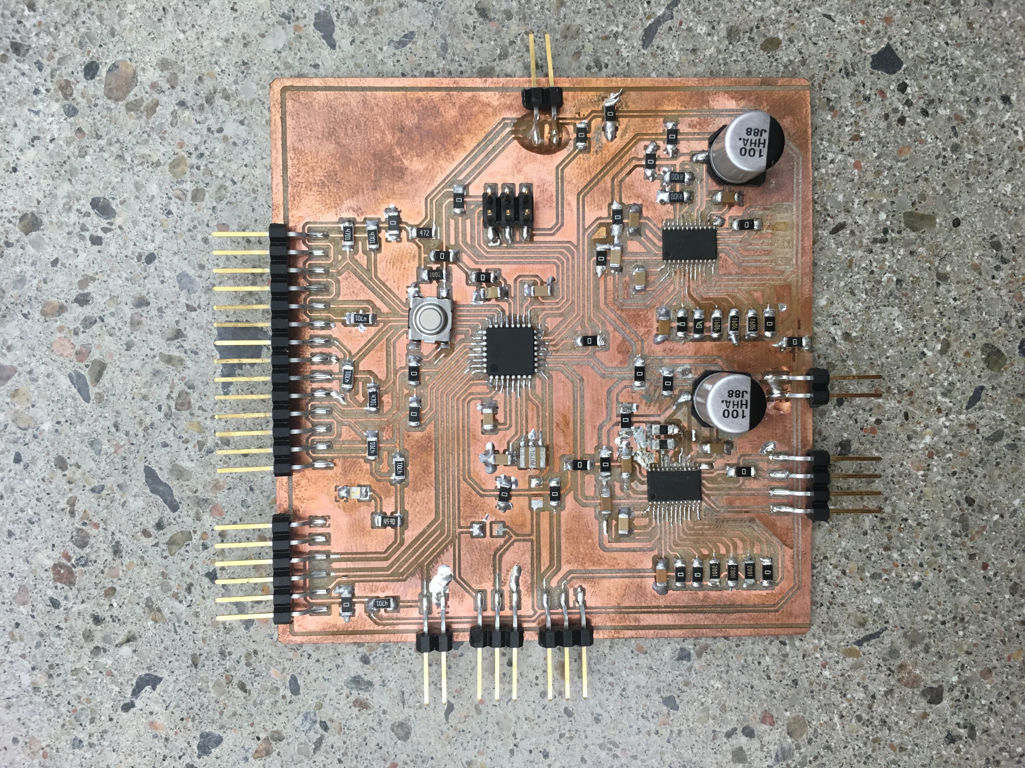
The big challenge for this board was the number of inputs and outputs. We used all the pins of the Atmega328p. It was a really interesting board to make because it was much more complex than the ones in the weekly projects. We have learned a lot about electronics by making this board.
You can refer to
Francis Lance site for more details about that part.
#8 - Software
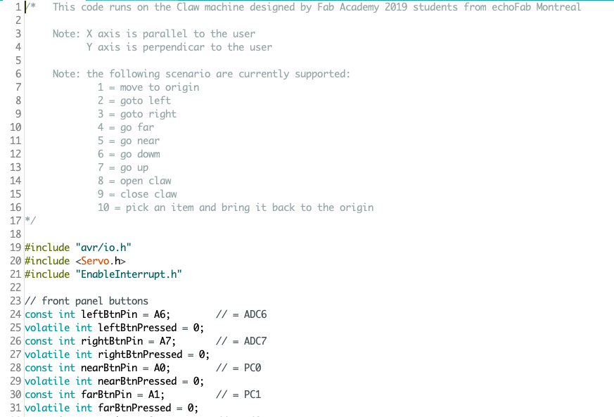
For the software, we were lucky enough to be able to create a lot of functions that were called directly in the main program. Also, we explored interrupts and interrupt routines to be able to make the machine much more responsive when the buttons are pressed.
You can refer to
Philippe Libioulle site for more details about that part.
To be able to develop the software in parallel with the hardware electronic, we designed a copy of the claw machine on a breadboard. This allowed us to test the code before putting it on the real machine.
#9 - Final assembly
For the final assembly, we connected all the inputs and outputs and neaten up the cables for better presentation. This was much easier because all our wires had shrink tube on it and also a plastic protector on the motor wires so that there was no friction on the wires to damage them.
This project was very interesting to learn all about the interconnectivity of all part. You can not build a machine completely independently of all the “middle part” What we mean with that is that all the connection between the small system we develop had a big issue on the performance of it. I know that if we built this machine for a second time, a lot of details will change. Like the axes where we learn about the flexibility of the material and the impact on the directions of the rods. We add an extra metal corner to support with that particular problem. We are glad we make it real in one piece and be able to understand better about mechanisms creating dynamic motion.
Here is our final video!
Here is our final slide!