Mechanical Design, Machine Design

week 15
May 1 and 15, 2019
This week's project is actually over two weeks. This project is special because it is a group project with all the EchoFab students. We have divided everyone's tasks according to their strengths and weaknesses. You can visit the group page right here or continue on this page to see my part. I am in charge of the electronic design part.
Designed the board for the group project
Research how to make a stepper motor drive
I did several researches on bi-polar motor drives and I came across this very interesting site. I learned about the different pololu drives. I had also heard about a board that was in a 3-axis scanner that looks a lot like our project and that's the smoothieboard. So I looked for more on this board. I found the plans online on github. So I decided to base myself on the drive part of this board.Here the smoothieboard.
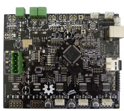
This is the part I will base my design on. This part has been taken from the github link above.
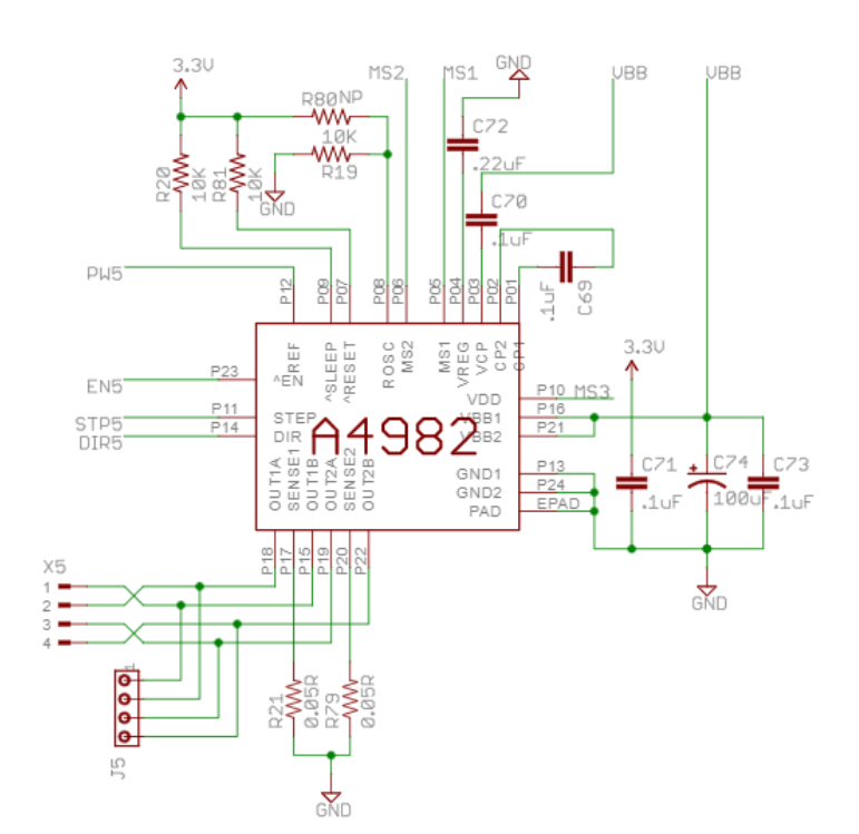
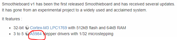
I read on the smoothieboard website that they changed the drive for a new one. So I had a doubt about the schematic above because it was not the same component. I'm lucky because it's a drop-in replacement. This means that the pinout is the same as the old chip.
Smoothieboard website.
What we need on the board.
As a team, we decided what we needed as an input/output on the board. Here is the list.
Designe the schematic
I decided to do the board with a microcontroller that we saw in the course that is the atmega328p. So I took back some of my design from week 11 and 12. This is the part I was able to reuse. Do not forget the 4 decoupling capacitors for each vcc (Pin 2,4,18,20).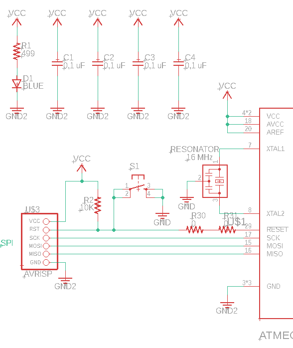
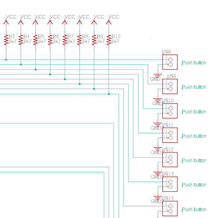
For the buttons and the limit switch, I used a pullup resistor of about 5k ohm (in my case 4,7k ohm). I connected them connected on a digital and analog pin but they are all used as digital.
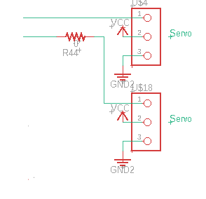
The servo motor was the simplest part because they already have their 2 power pins and simply connected the servo motor to a digital pin. BE CAREFUL, do not put a pull-up resistor on the data line because it will not work.
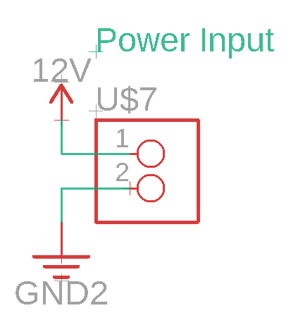
I put a connector in to be able to power my board with 12V independently of the 5V. So I simply put a connector with a 12V vcc component.
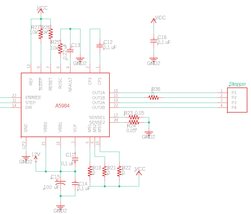
Finally the drive for the two stepper motors. After analyzing the schematic, I replicated much of the smoothieboard schema and then adapted it into our scenarios. The good thing about this chip is that it will control its current itself so as not to exceed its limit of 2A. On the other hand, if you use more than 1A it is important to put a heatsink on the component otherwise it will become hot and you will damage it. If you want to limit the current in the drive, simply put a potentiometer on the pin ref to reduce the voltage. It should not be forgotten that the chip must have a decoupling capacitor.
Designe the schematic
One important thing when designing the board is to put the crystal(Yellow) and decoupling capacitors (Blue) as close as possible to the microcontrollers.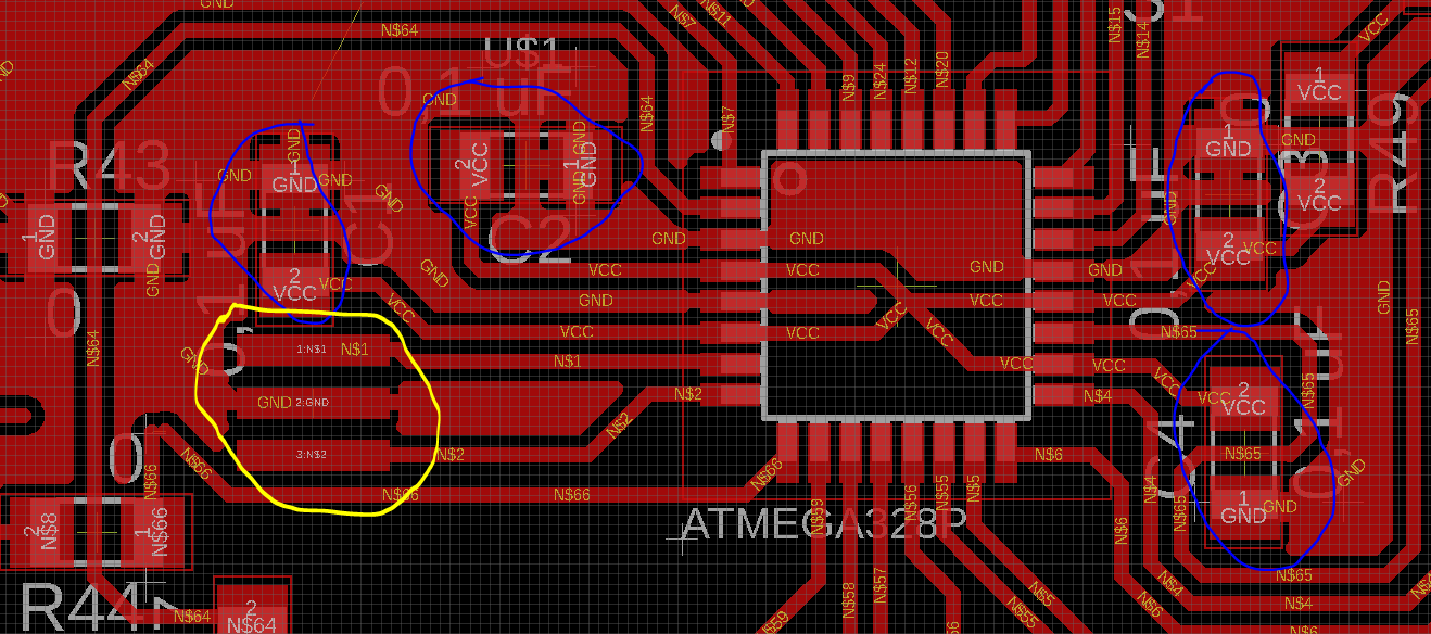
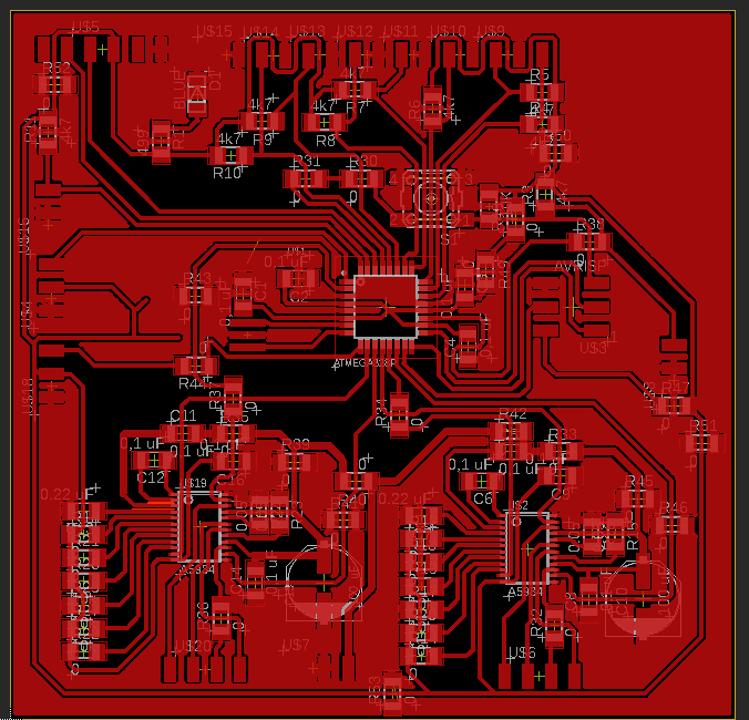
Here is the final board and it is a good practice to put a ratsnest connected to the ground.
Milling and soldering the board.
Here the board during the milling.
Here the board when it's done.

This is the soldered board. One little trick I noticed during the soldering process was to start with the lowest components from the center to the outside. Thereafter, we can make the components higher. This avoids hitting the higher components when I am soldering a lower component.

Testing the board.
Problem encountered Here is an image of a problem encountered. Unfortunately, there was a short circuit between two pins of the drive. This killed the drive but also damaged the trace. So we had to repair the trace.
After changing the drive and repairing the trace, everything worked fine.

Result
Here is a short video when I was testing the most important part of the board which is the stepper motors on both drives. It was working really well.
You can download all the files of this week right here.