Week 09: Embedded Programming
This week we learn how to identify relevant information in a microcontroller data sheet and implement programming protocols.
Individual assignment
Data Sheet
To start programming, first I think you should know the specifications of the data sheet of the ATtiny44. The pinout is shown as a simple table or it can include a diagram. It represents the connection between components that facilitate repair work in the search for short circuits or circuit interruptions. As you can see in the image, the pinout numbering is different from that of the Arduino programmed pins. However, some share more than one function.
I understood that they have digital inputs that differ from the analog ones because they are able to "understand" only two levels of signal, LOW or values close to 0 V and HIGH or values close to 5 V. On the other hand, the analog inputs are capable to read voltage values from 0 to 5 Volts. I will use the Attiny44 so I will show an image with its pins.
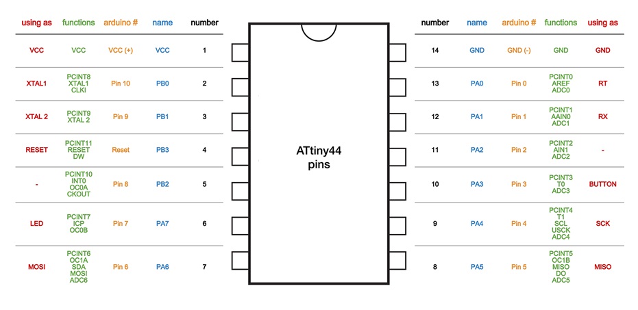 Fig.01 - Pin Configuration ATtiny44
 Program Board
We will need an ISP programmer, I have created another ISP, since the one I had does not work because one of its routes was broken and there was no way to repair the road, for that I followed this tutorial FabISP: Programming . The helloworld that was manufactured in week 7 . Also, an FTDI that sends the code to the microcontroller with TX and Rx data pins.
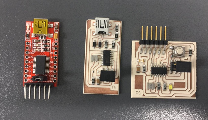 Fig.02 - ISP, FTDI y HelloWorld
 Unlike most USB to TTL serial adapters, this adapter supports 5V and 3.3V operations. Simply configure the jumper as necessary to choose between 5V and 3.3V as indicated on the plate. This adapter allows the programming of microprocessors like ARM, AVR. Serial communication with many devices such as GPS devices and serial terminals in devices such as the Raspberry Pi. The main connector has 6 pins:
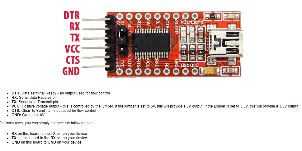 Fig.02 - FTDI Data sheet
 We connect the cables to the ISP, these are connected by dupont cables, as I understand it does not matter the colors, but if you connect them in the correct pin, you can burn the ISP. It must respect and recognize which correspond to MOSI, MISO, GND
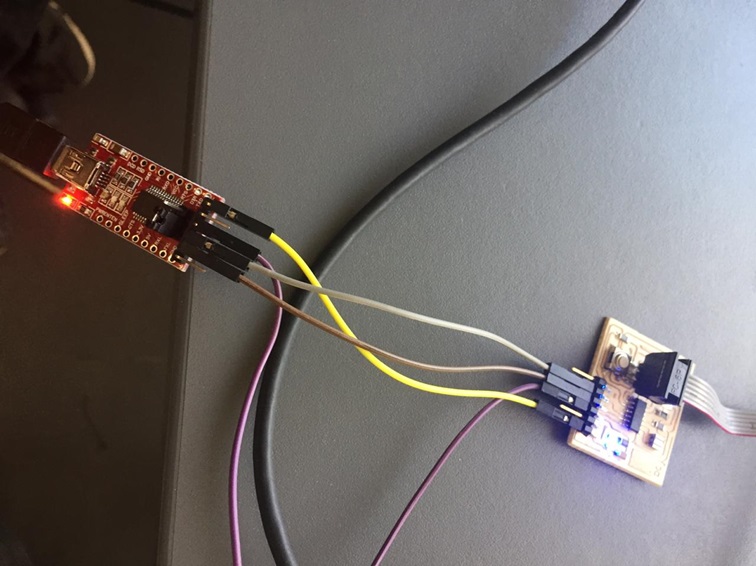 Fig.03 - Cables Dupont
 If you connect the correct pins, the wiring would look something like this.
We download the software from the page Arduino. This is a free program that has a large variety of examples on the Internet, so that faults and responses are more accessible to find them.
We can find them for windows, mac and linux. In my case I will use windows version 1.6.11
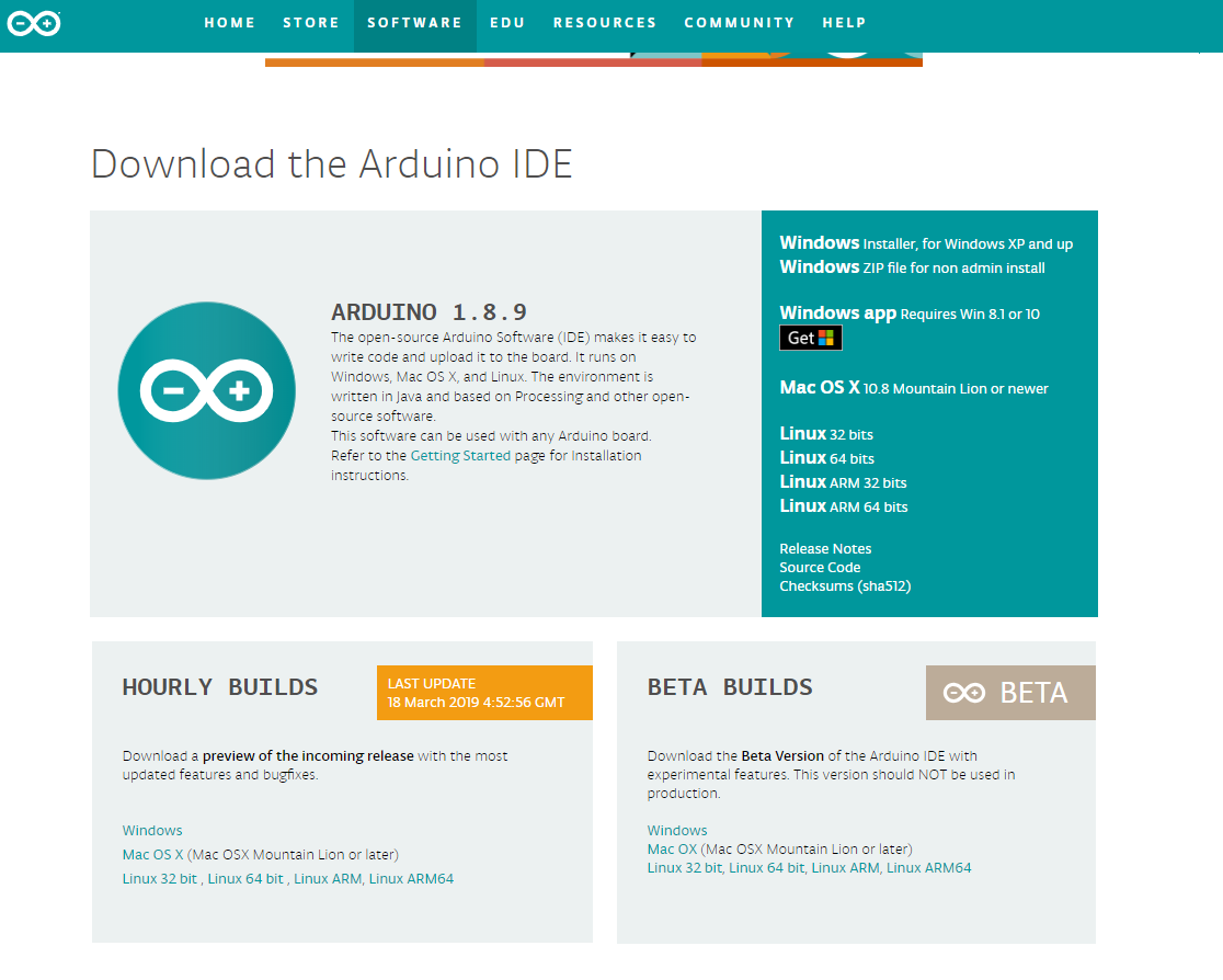 Fig.05 - Download Arduino
 It is necessary to install the ATtiny extensions for the Arduino.
 Download Extensiones ATtiny
 Fig.06 - Extensions ATtiny
I was working with the FabLab CIT computers and on one of my colleagues' computers while learning to use this new software called Arduino. However, when I opened the program and connected the ISP to my computer, I was surprised that I did not read my license plates. The reason was because in the FabLab all the drivers were already installed.
Start by following the tutorial called "Using the GNU AVR toolchain on Windows 10" , I installed the Atmenl AVR Toolchain for windows, the GNU make and the avrdude. Open advanced system configuration, environment variables, edit the path and this is the most important thing to examine the location of the 3 files. It is very important to locate the avrdude in programfiles and toolchain and GNU in programfiles (x86) otherwise the process will not be completed.
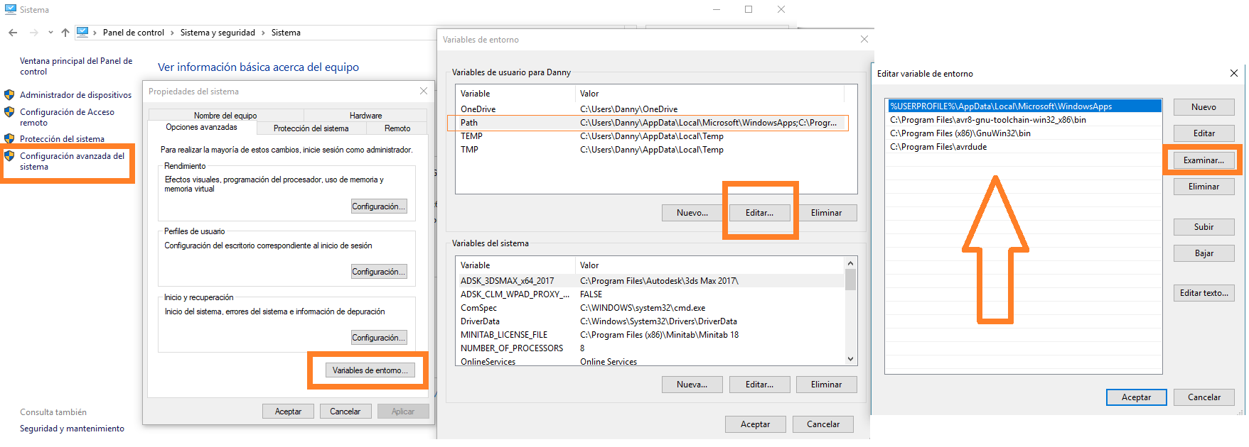 Fig.07 - ISP Failed
 Download the "Zadig" that allows the installation of the driver of the connection of USBtiny.
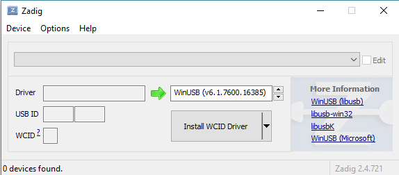 Fig.08 - Zadig
 The error that appeared at the beginning was "avrdude.exe: Error: Could not find the USBtiny device (0x1781 / 0xc9f)", as I mentioned the solution is to correctly locate the files in programfiles and programfiles (x86). However, verify that your usb cable works correctly.
To confirm the installation it is enough to open GIT and write make -v or avr-gcc --version if it appears as in the image everything was installed correctly.
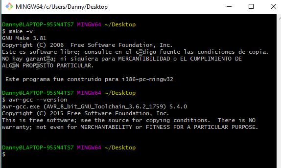 Fig.09 - Error USBtiny (0x1781 / 0xc9f)
 Once the tutorial "Using the GNU AVR toolchain on Windows 10" is complete, the tools allow us to read the ISP board and the ATtiny microcontrollers. For the development of my programming I need to select the Attiny44 board, the Attiny44 processor and a 20 MHz clock external
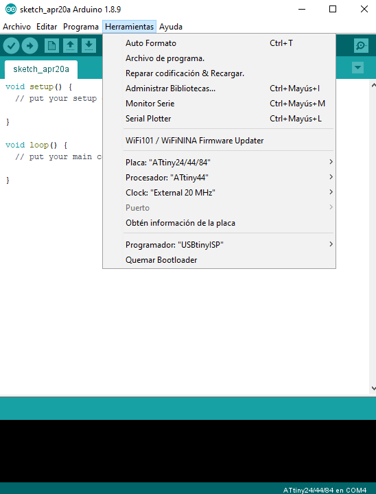 Fig.10 - Configuration Tools
 In the arduino IDE, we select tools, burn bootloader.
At the time of loading the first error occurred, one of the pins of the ATtiny44 was loose.
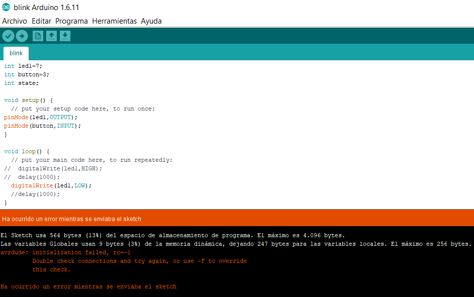 Fig.11 - Initialization Failed rc=-1
 It was solved by adding flux to one of the pins in helloworld, the code managed to start. After a few seconds, a message will appear that shows that you burned the boot loader correctly.
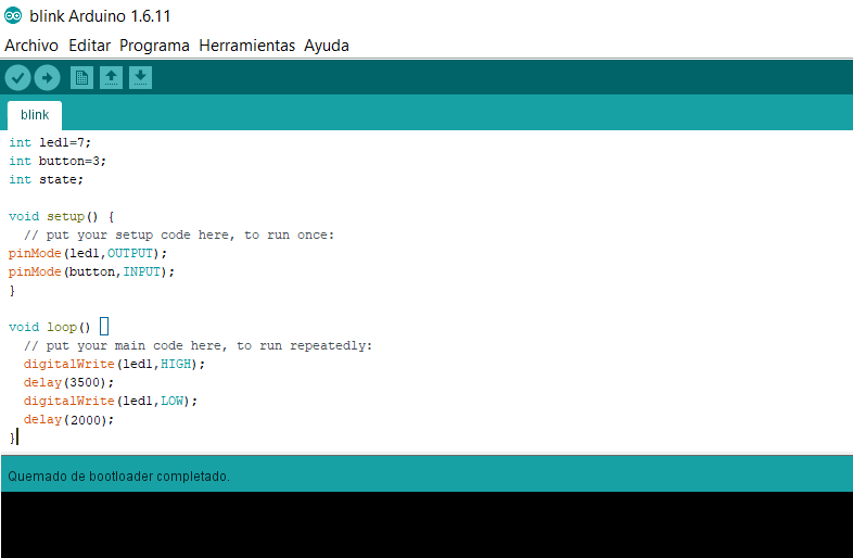 Fig.12 - Bootloader
 Once the code is checked, we upload this data to the board. If everything was written correctly, a message will appear with the amount of bytes that the sketch represents.
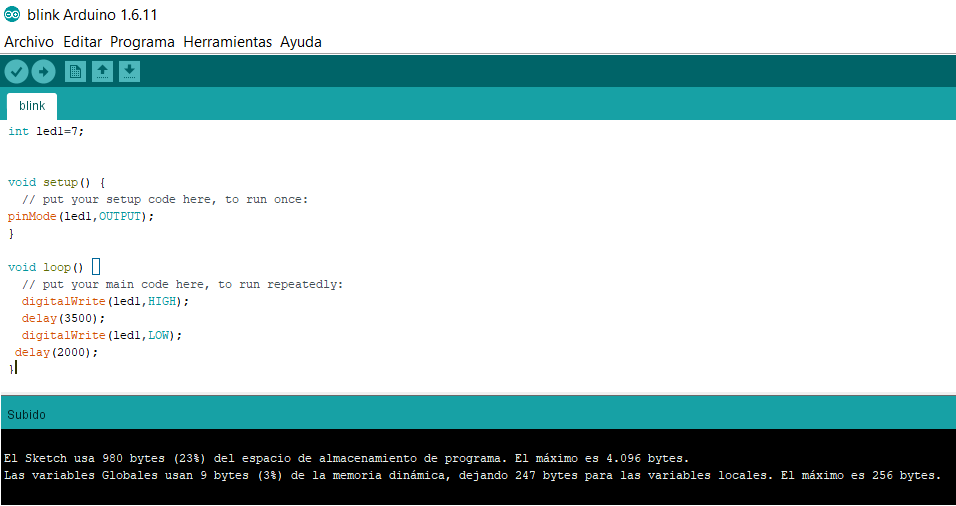 Fig.13 - Upload
 If you follow the correct procedure, the result will be shown like this. My LED turns on every three and a half seconds and turns off for two seconds
Files
You can download files here.
BlinkButton
Group assignment
My group contribution was to compare the workflows of performance and development for other architectures, in my case arduino
C programming
In the C language it is important to know the difference between ports A and B.
Ports A are bidirectional ports of 8 bits that are normally used as analog pins, while ports B are bidirectional 4 bits and are usually used as digital pins.
For the assignment of inputs we will use the analog converter (page 129 from the datasheet of attiny44) and the assignment of outputs we use the PWM signal (page 69 of the datasheet). We must define the pin to use, in this case the line DDRA = (1 << PA7) indicates that we will use the pinA7.
The line PORTA = (1 << PA7) indicates that we are setting its value to 1, that is, HIGH. While the line PORTA = (0 << PA7); we force its value to a 0, that is, a LOW.
In order to load the code, we need the plate, our ISP and the FTDI to upload the code, we must also configure our microcontroller with its features, the ISP and how to upload the code.
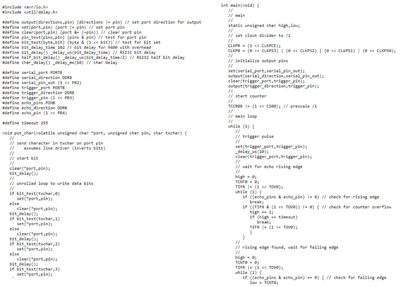 Fig.15 - C programming
 Arduino programming
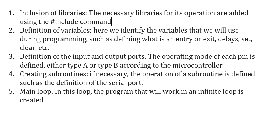
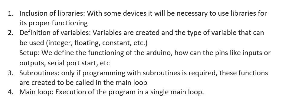
For the use of an Arduino, the programming language is with a language similar to C. In this case the structure is as follows:
To upload the code with an Arduino, it is much simpler since only the type of board is defined, the serial port to which it is connected and the code is loaded. It is the simplest way to work.
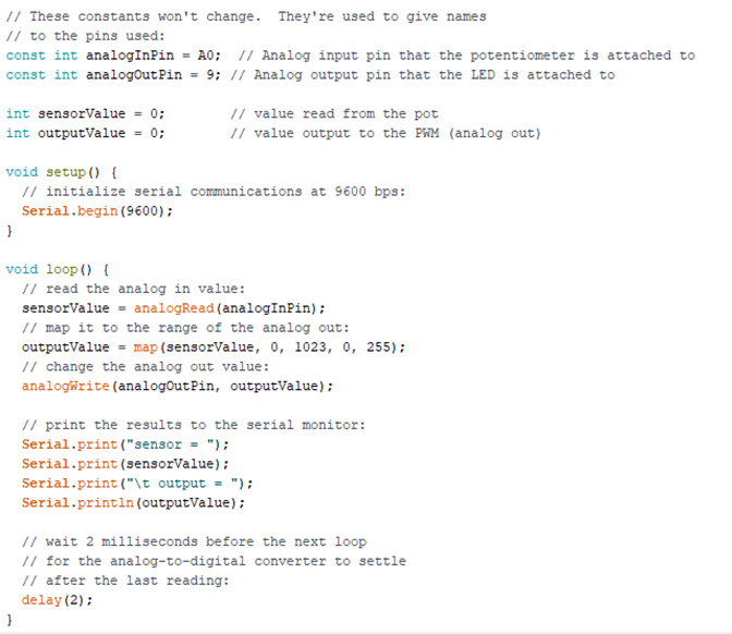 Fig.16 - Arduino programming
 Raspberry
To work with Raspberry, we must use Python as a programming code. It is a language that is beginning to be used for several applications, being the raspberry the most used for applications of the internet type of things. The basic structure of the programming is the following:
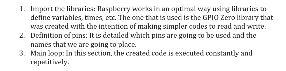
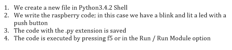
In this case no code is uploaded to the board, since we use an operating system of the same Raspberry, which is necessary for the operation of this. The workflow for the operation of the code is as follows:
Blink:
Button:
To see all the documentation of the group work, you can visit the CIT page.
Group Files
You can download group files here.
BlinkButton
What questions do you have? - What would you like to learn more about?
I learned how to use the data sheet to know the capacity of microcontrollers.
Also, the main question was: How could the FTDI be used in the creation of an interface with Firefly? On the other hand, I would like to learn more about the ATmega328, since it has more digital and analog pins which I could use in my final project.