Week 07: Electronics Design
This week we create a new electronic board based of the Hello World board
Individual assignment
Software
EAGLE is a program for designing diagrams and PCBs with auto-router famous around the world of DiY electronic projects, because many versions of this program have a Freeware license and a large number of component libraries around the network. Therefore, for the creation of PCB I will use this program in the windows version.
 Fig.01 - Autodesk Eagle
 The PCB design in EAGLE is complemented by two processes. First, the software shows us a schematic window, here the architecture is designed with the components that we need for the board to work. Then it enables us a board in which components are imported with their symbols and we have to connect them arbitrarily by routing all the pins.
A well-designed scheme is critical to the overall PCB design process, this will increase or reduce the working hours in the development of the board.
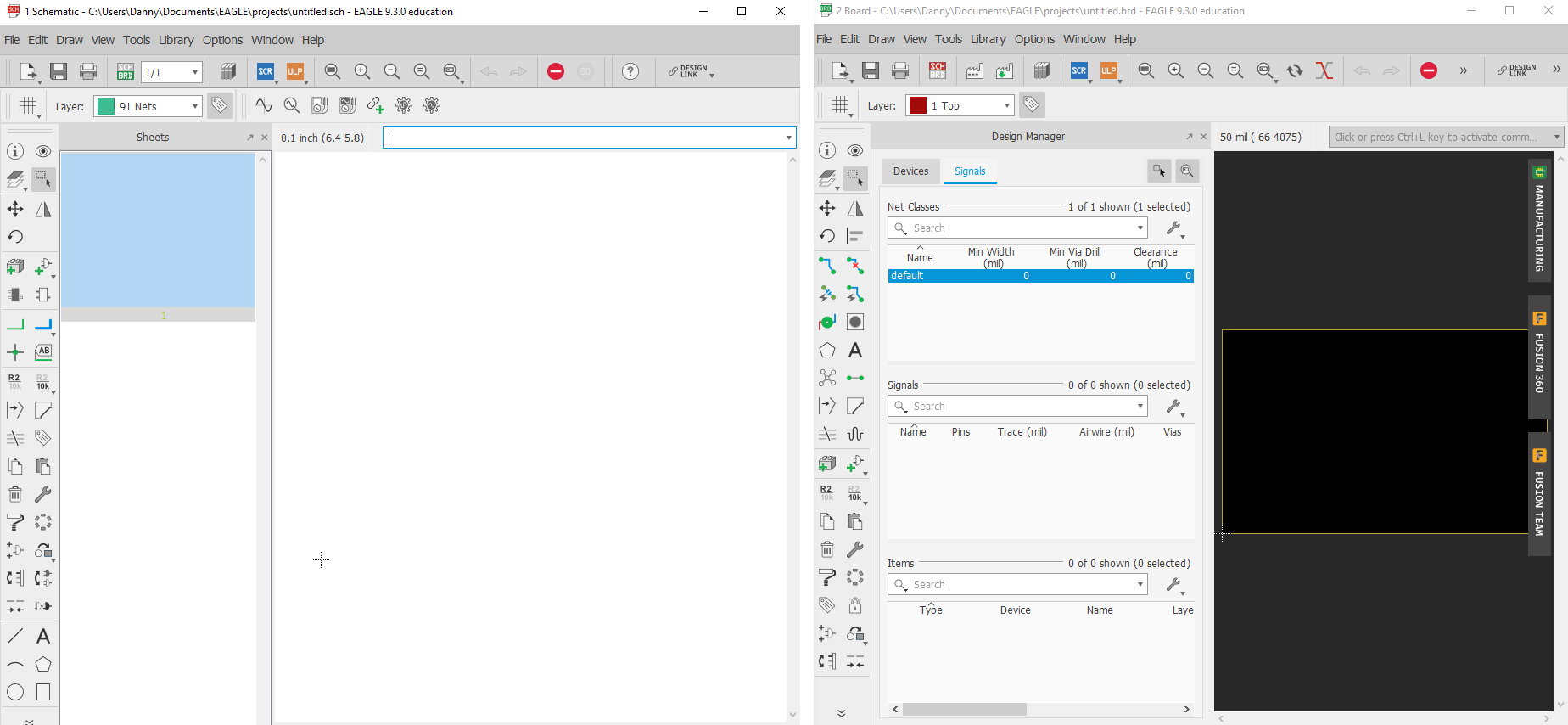 Fig.02 - Sch & Board
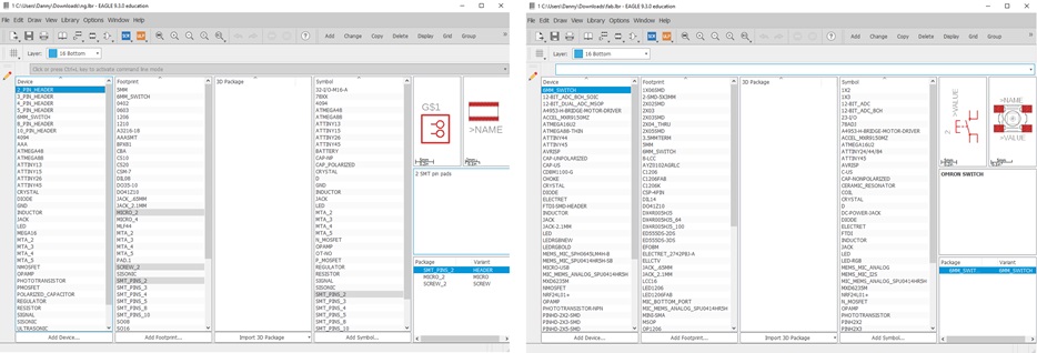
 One of the advantages of the Eagle software is that the interface shows the name, icon and code. There are several libraries where you can find any missing component in the fablab network, so I found the Neil's library and components of the Fab library. I downloaded them and moved them to the library folder of the Eagle program.
 Neil Library
 Fab Library
Fig.03 - Libraries Download
To add the components it is necessary to write in the "ADD" command box, a window will open in which we will observe all the current components, select the one that adds "nd or fab" and we will find the symbology as GND.
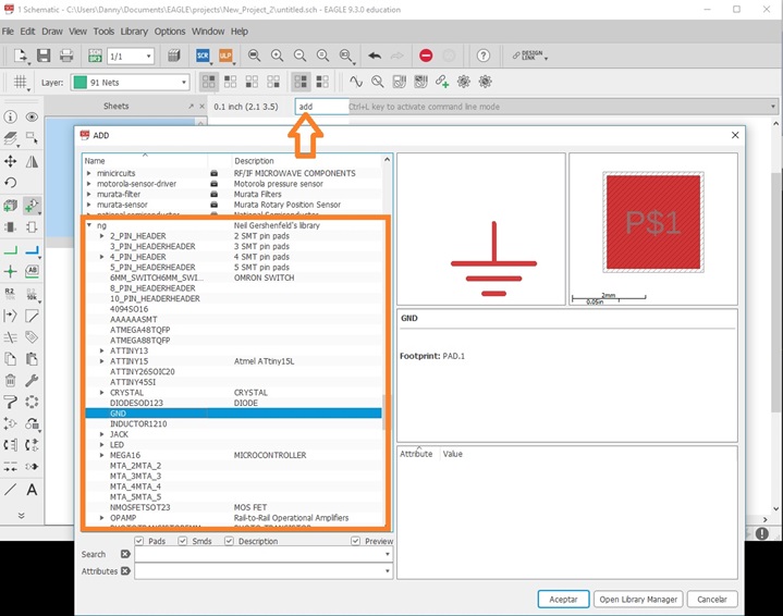 Fig.04 - Add components
 After adding the components, with the net order tool I managed to wire the routes, for keeping order criteria I separated the components like GND, LED, BUTTON so as not to have several lines that mess up the design.
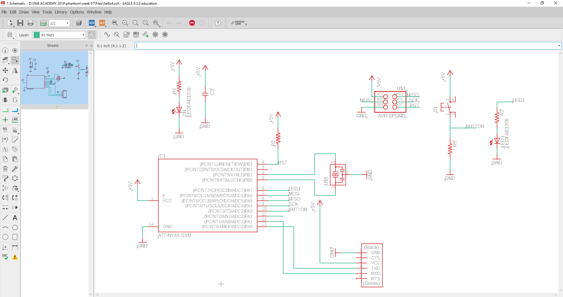 Fig.05 - Schematic
 Once the schematic is ready, we generate the board to order the components. The program shows us all the components to use, these are connected with a yellow line so there is no way to get lost by joining them if we are new using the Eagle program.
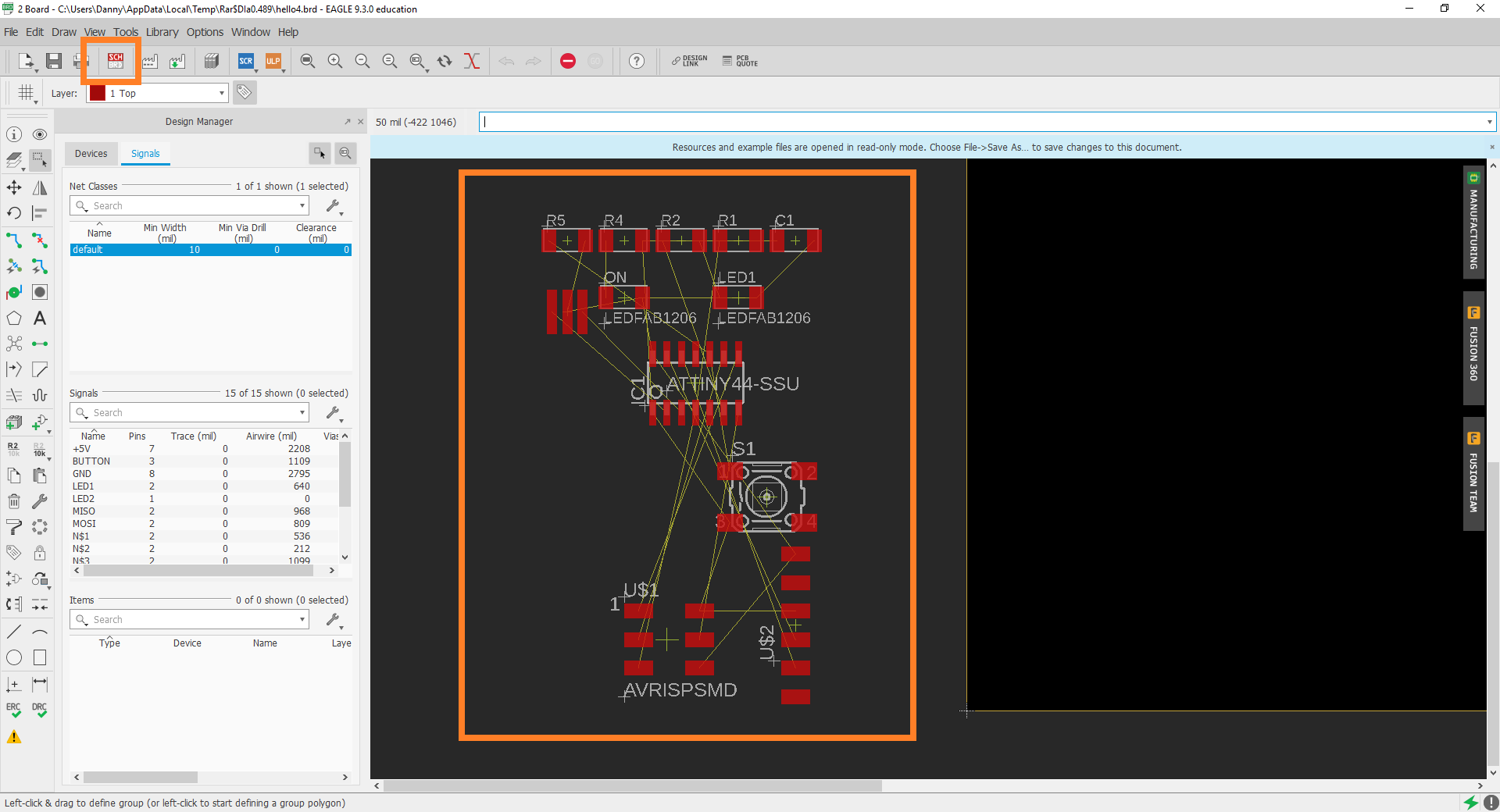 Fig.05 - Board
 It cost me initially to interact with the software, but with the passage of time I managed to fine-tune the routes, I learned that you can create jumps between components and thus compress the design of the board.
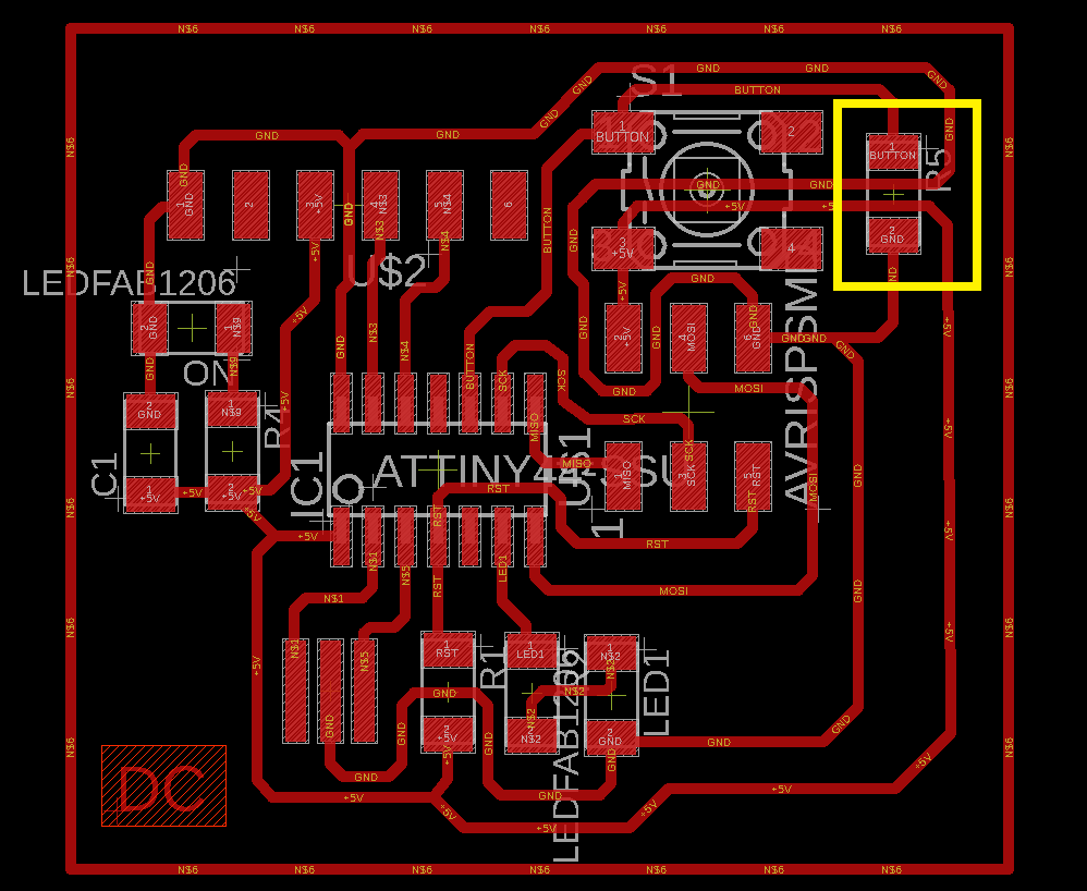 Fig.06 - Board
 Once the design on the board is finished, we verify the design and connections with the DRC tool. The common error that appears if we add our initials is related to the text source, in my case with the DC symbol; therefore, I prefer to add the text from any image editor such as photoshop, paint, etc.
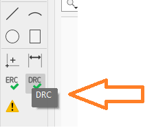 Fig.07 - DCR
 To achieve that the electronic board is manufactured well, it must be secured using the DRC (Design Rules Check), here you can configure some parameters such as the width of the separation between tracks, and the tracks themselves, then I show the parameters that I use .
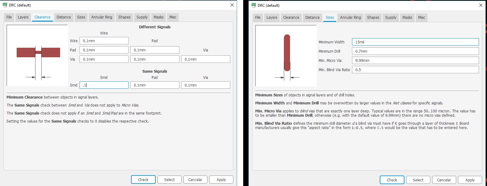 Fig.07 - DCR
 To achieve export we need to turn off some layers, otherwise these would appear in the design of the plate.
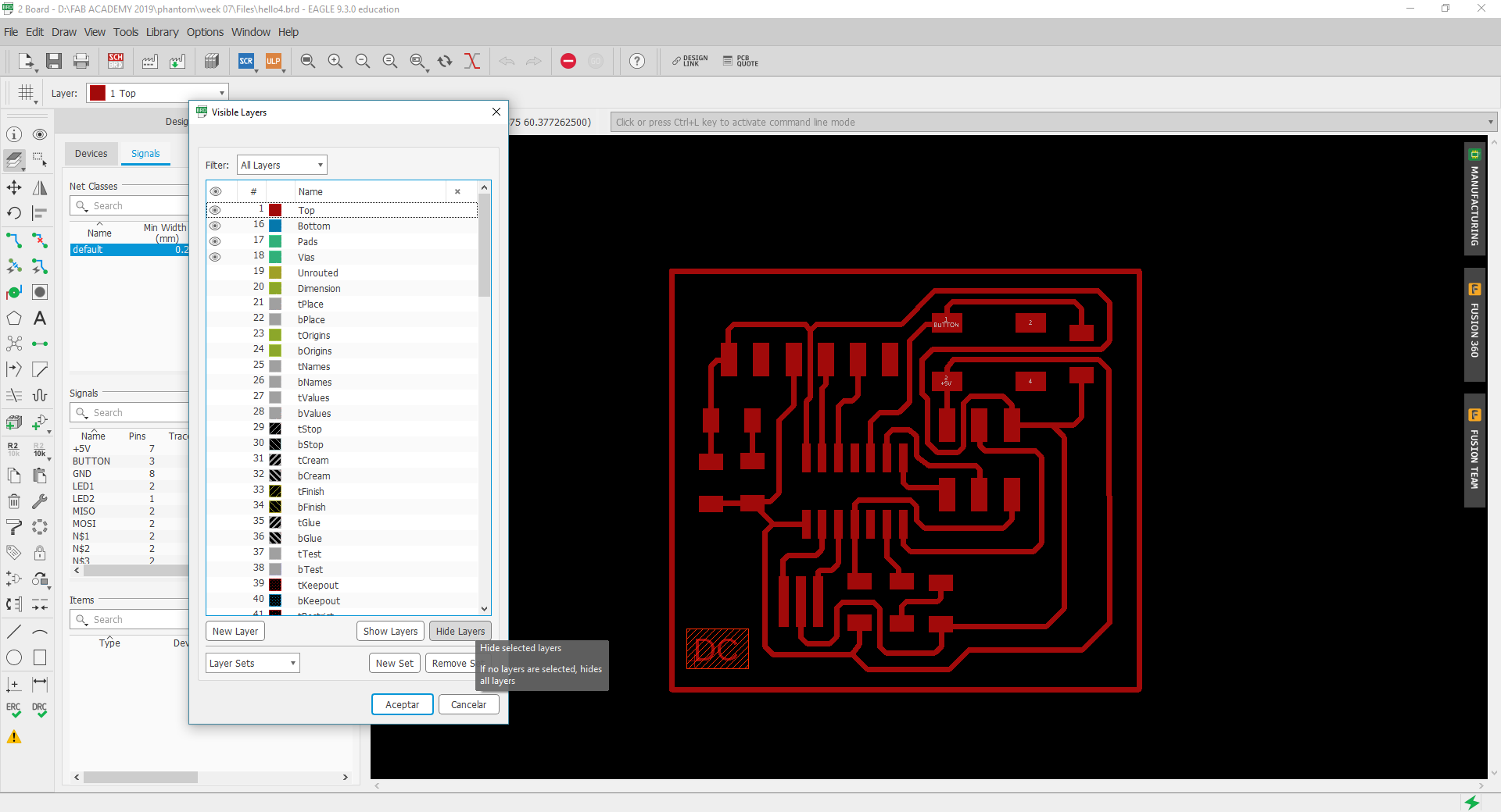 Fig.08 - Layers
 To export we use the tool file / export / image, a window will open in which we will choose the following options: monochrome, a resolution of 1024dpi and the area will be window.
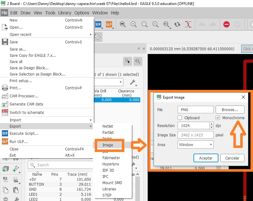 Fig.09 - PNG Export
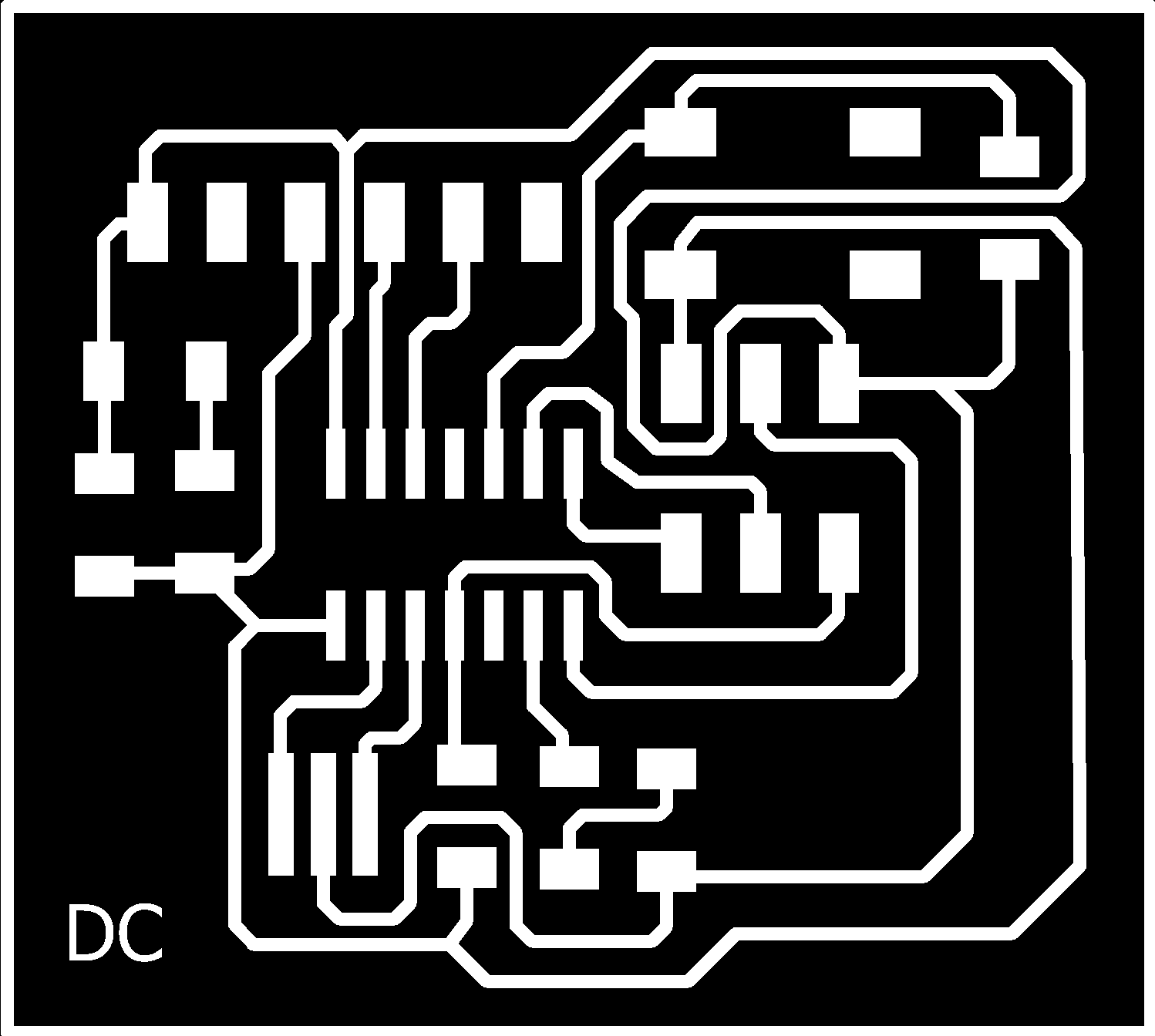
 While xporting the design in PNG format, we will observe in detail how the final result would be. It must be taken into account if some lines are very thin.
 Fig.10 - PNG
 To generate the G code, we go to the Fab Modules page and in the PBC traces we choose the 1/64 one. We generate a tool diameter of 0.1, 20 number of offsets to have a better work area and a rotation speed of 8000 rpm.
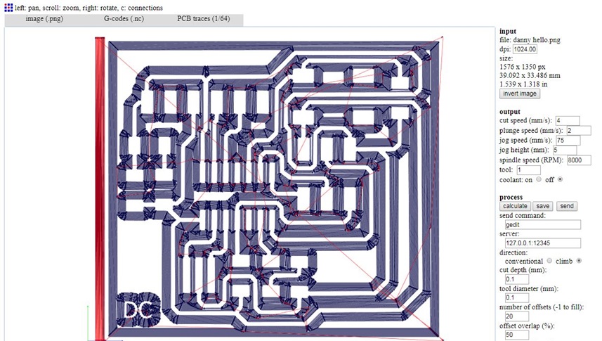 Fig.11 - G-Code
 We insert the G code in the CNC software with the "Cut" tool, we click on output and it will start generating the routes on the board. We must be careful in the pressure exerted by insurance on the Z axis, sometimes subtract irregularly.
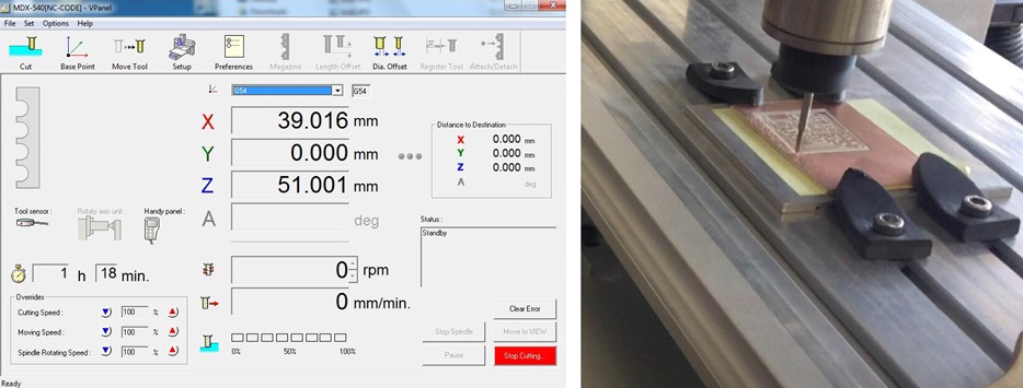 Fig.12 - CNC Roland Modela
 After the CNC completes the plate manufacturing process, we must prove continuity in the routes. Sometimes, in the area where the ATtiny is located copper may be missing and this will prevent the plate from working properly.
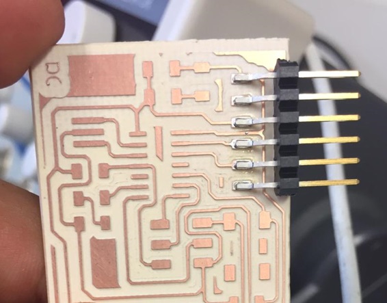 Fig.13 - DC HelloWorld
 Components
We must know electronic components such as LED, voltage, current, capacitors, resistors, etc. In addition, it is necessary to familiarize ourselves with the schematic symbols, and that we will need to interact with these components in the final project's manufacture.
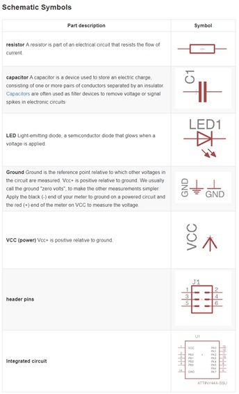 Fig.14 - Schematic symbols
 I measured the value of the resistors and the capacitor to compare them with the standard values, as it is observed the real value varies between 0.01-0.02 units.
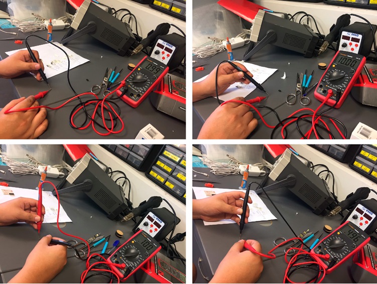 Fig.15 - Value of resistors
 At the suggestion of my tutor, I write the name of the materials with their corresponding symbology and attached the component stuck with tape on a sheet. In this way, it became very easy for me to adapt to new terms and symbols.
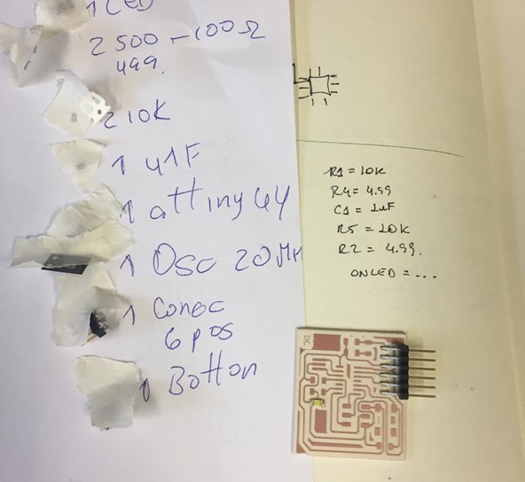 Fig.16 - Components
 With the practice I managed to weld with a better finish, on this occasion unlike my ISP, I took care when welding the pieces.
In addition, I realized that the LEDs had polarity. The first one that solde was random, but the second one did not turn on. My local instructor told me that some components have a colored line, in the case that does not exist, it is checked with the multimeter and we will take into account the direction of the route.
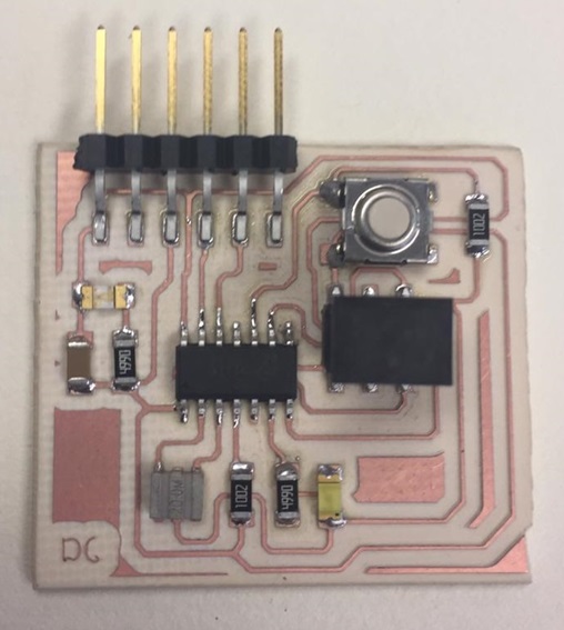 Fig.17 - DC HelloWorld
 With a DFRduino I check if my LEDs light up, to my surprise they turned on the two LEDs of my design at the same time. One of the heads of the CIT laboratory told me that it could be an ATtiny44 error that was solved at the time of programming.
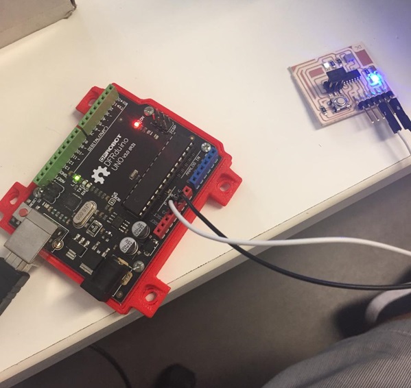 Fig.18 - LED
 Group assignment
Test equipment
For the group test a plate was designed in which a led and a welding bridge were added on a button, to know the current consumption and to use the oscilloscope.
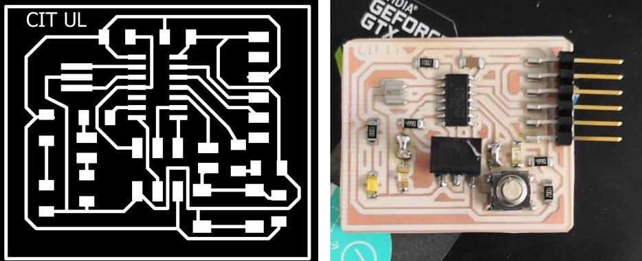 Fig.19 - PNG
 We can see how one LED is activated and the other does not, according to the programming, with an LED that has a voltage of 5 V, while the other has a voltage of 2.5 V. The attany data sheet must be verified to verify the correct voltage.
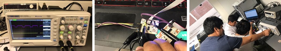 Fig.20 - Group Test
 To see all the documentation of the group work, you can visit the CIT page.
Files
You can download files here.
HelloWorld BoardHelloWorld Schematic
Board PNG
Danny Hello G-Code File