Digital Incentive Spirometer
One of the standard tests conducted in hospitals to measure the pulmonary functions is called the spirometry test. Spirometry test assess how well the human lungs are by using a device called spirometer. The spirometer is a clinical device that is used to measure the amount of air that patient can inhale and exhale during the respiratory system as well as the flow rate.
The aim of this project is to design, build and test a prototype of a portable spirometer that can be used to measure the lung volume and air flow rate. Also, the device can be used to monitor the progress of the patient health status, especially after a surgery or after taking a series of medical sessions. Data obtained from the device will be recorded as future reference to help in diagnosis some certain lung diseases (such as COPD and Asthma). The diseases can be diagnosis by comparing the recorded data of the lung functions to the expected levels of functions.
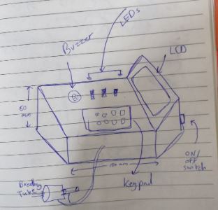
The device is easy to use as it has multiple interface components like LCD, LEDs and buzzer. The test is painless, and device is safe to be used.
This is how I imagined and sketched the device:
Background information
In digital spirometers, flow rate and volume of the exhaled and inhaled air can be measured using a pressure-based flowmeter. The flowmeter has a mounted resistance element inside that is built to create a pressure drop. If the flow is laminar, then the flow rate is proportional to the square root of pressure difference. The average air pressure that human can achieve is about 2 PSI. Many parameters can be measured from the spirometry test, some of them are: Forced Vital Capacity (FVC) which is defined as the largest amount of air that patients can blow out after they take biggest breath in. Forced Expiratory Volume (FEV1) which is defined as the amount of air that patients can blow out of their lungs in the first second. Maximum Voluntary Ventilation (MVV) The volume of gas that can be breathed in 15 seconds when a person breathes as deeply and quickly as possible.
The procedure of doing the FVC and FEV1 is as following:
1- Users place the mouthpiece of the spirometer in their mouth.
2- They start by taking normal breathing.
3- After that, they take a deep breath to fill their lungs with air.
4- Finally, they blow into the mouthpiece as hard and as fast as they can until their lungs became empty.
The procedure of doing the MVV test is as following:
1- Users place the mouthpiece of the spirometer in their mouth.
2- For 12 to 15 seconds they breath rapidly and deeply.
In this project, the user will first enter his/her ID and age so we know the identiity of the person that he is doing the test. Then, he will chose the type of test he would like to preform. Then, instructions will be displayed on the LCD on how to conduct this test. Then, depending of the type of the test, LED and buzzer will turn on. After finishing the test, the LED will turn off. Data and result of the test will be displayed on the LCD.
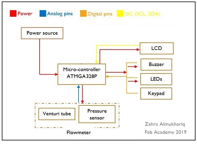
System components/elements:
1- Micro-controller based on ATMEGA328P
2- 20x4 LCD
3- 4x5 keypad
4- Buzzer
5- flowmeter desgined based on pressure difference
6- LEDs
7- ON/OFF switch
8- Battery
And the figure below shows how all the elements are connected to each other:
Flowmeter based on pressure sensor
Flowmeter circuit design
In this project a differential pressure sensor will be used in venturi tube to create a flowmeter that will measure the air flow rate and lung volume.
The final selection of the pressure sensor that will be used for the project is NPA-500B-10WD. This sensor has been chosen to be used in the project over the other sensor available due to the following reasons:
1- The sensor gives an analog amplified output.
2- The sensor is calibrated.
3- The supply voltage of the sensor is 5 volts.
4- It is a differential pressure senor with the range of -0.36PSI to +0.36PSI.
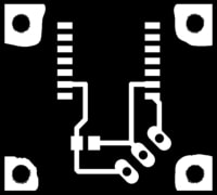
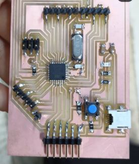
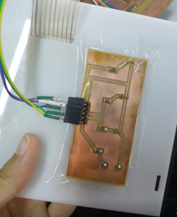
Since the sensor is SMD, the first step was to make a PCB for it with headers in order to be able to use the sensor. The PCB has been made based on the circuit layout provided in the datasheet. The figure below shows the standard circuit connection from the datasheet and the PCB made.
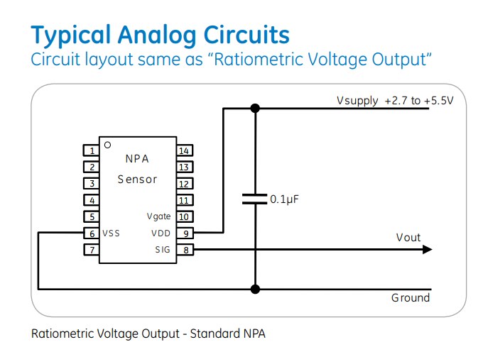
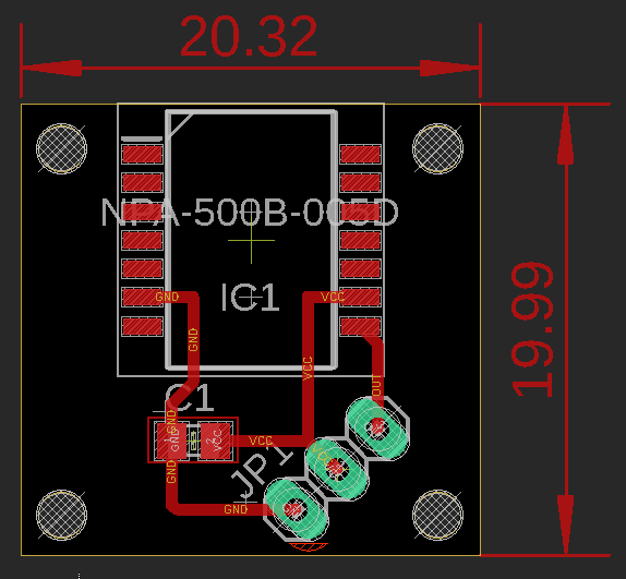
And here are the circuit specifications:
1- Width of tracks = 20 mill.
2- Capacitor footprint is C0805.
3- Board size = 20.32x19.99 mm.
4- Headers connect to the sensor (GND, VCC AND VOUT).
5- Holes for 2mm screws to fix the PCB inside the case later on.
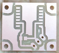
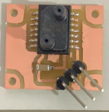
After designing the circuit, I have printed the PCB on a single layer board through Roland Mill SRM-20 machine and by using fab modules then, I soldered the components on it.
After done with the circuit, I have looked at the relationship between the output voltage and the range of pressure applied. In the datasheet they mentioned that at the minimum value of pressure, the output voltage is 0.5 volts, while at the maximum pressure, the value of the output voltage is 4.5 volts. The equation to calculate the pressure based on the measured voltage is provided in the datasheet as:
P_out = P_min + ((out - out_min)/(out_max- out_min )) x (P_max- P_min)
Where, P is the calculated pressure
out is the measured output voltage
P_min is the minimum pressure of the sensor (and for our sensor it equals to -0.36PSI).
P_max is the maximum pressure of the sensor (and for our sensor it equals to +0.36PSI).
out_max is the maximum output voltage (according to the datasheet it equals to 4.5v).
out_min is the minimum output voltage (according to the datasheet it equals to 0.5v).
Therefore, by substituting the values in the equation the following table has been provided to estimate at each output voltage how much the value of pressure is:
| output voltage | calculated pressure in PSI | converted pressure in pa |
|---|---|---|
| 0.5 | -0.36 | -2482.11 |
| 0.6 | -0.342 | -2358 |
| 0.7 | -0.324 | -2233.90 |
| 0.8 | -0.306 | -2109.7957 |
| 0.9 | -0.288 | -1985.69 |
| 1 | -0.27 | -1861.58 |
| 1.1 | -0.252 | -1737.4788 |
| 1.2 | -0.234 | -1613.37 |
| 1.3 | -0.216 | -1489.26 |
| 1.4 | -0.198 | -1365.16 |
| 1.5 | -0.18 | -1241.056 |
| 1.6 | -0.162 | -1116.95 |
| 1.7 | -0.144 | -992.845 |
| 1.8 | -0.126 | -868.739 |
| 1.9 | -0.108 | -744.63 |
| 2 | -0.09 | -620.528 |
| 2.1 | -0.072 | -496.4 |
| 2.2 | -0.054 | -372.3 |
| 2.3 | -0.036 | -248.21 |
| 2.4 | -0.018 | -124.1 |
| 2.5 | 0 | 0 |
Then, the following graph has been plotted in excel to get the straight line equation.
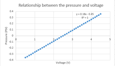
The equation obtained from this graph is: Pressure = 0.18(voltage) – 0.45
Example:
If we want to find the voltage at pressure of 0.2PSI, then:
Voltage = (Pressure+0.45)/(0.18) = 3.611 volts
Hence, the following code has been written in arduino IDE to find the air flow rate and volume from the sensor reading:
int analogInPin = A0;    // pin connected to the sensor
float SensorVoltage;
float pressure_psi;
float pressure_in_pa;
float Flow_rate;
int SensorValue;
float volume = 0;

void setup() {
  Serial.begin (9600);
}

void loop() {

  SensorValue = analogRead(analogInPin); // read the analog in value.
  SensorVoltage = (SensorValue*(5/1023.0)) ; //measuring voltage.

  pressure_psi = (0.18*(SensorVoltage)-0.45); //converting voltage value into pressre in PSI.
  pressure_in_pa = pressure_psi * 6894.7572932; //converting voltage value into pressre in Pascal as 1 PSI = 6894.7572932 Pascals.

  //pressure is negative during the inhale period, so we get flow in negative & pressure is positive during the exhale period so we get flow in positive:
  if (pressure_in_pa < 0)
  {
  pressure_in_pa = pressure_in_pa * -1;
  Flow_rate=-(0.086*sqrt(pressure_in_pa));
  }
  else
  {
  Flow_rate=0.086*sqrt(pressure_in_pa);
  }

  volume = Flow_rate*0.001 + volume; // Total volume (essentially integrated over time)

  Serial.print("volume =");
  Serial.println(volume);

  delay(1);
}
And this is how the sensor was connected to my own micro-controller circuit:

My own micro-controller board has been designed already in week 11. From the input week, I was planning to keep and use this board in my final project as all the components will be connected to it. Here are the steps again of creating this board using ATmega328P micro-contoller.
About the ATmega238P:
-
Operating Voltage: 1.8 - 5.5V
-
6-channel 10-bit ADC (Analog-to-digital convertors)
-
Six PWM Channels
-
Two 8-bit Timer/Counters and one 16-bit Timer/Counter
-
High Endurance Non-volatile Memory Segments
-
23 Programmable I/O Lines
Check the datasheet of the ATMEGA328P micro-controller by clicking on this link. The figure below shows the pins layout of the micro-controller Atmega328P:
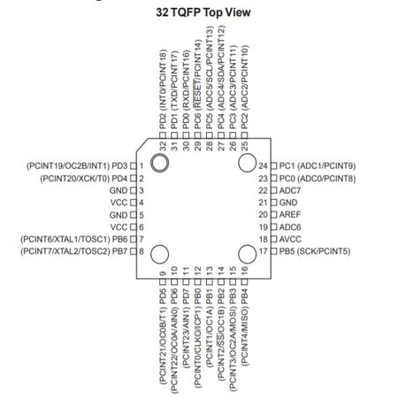
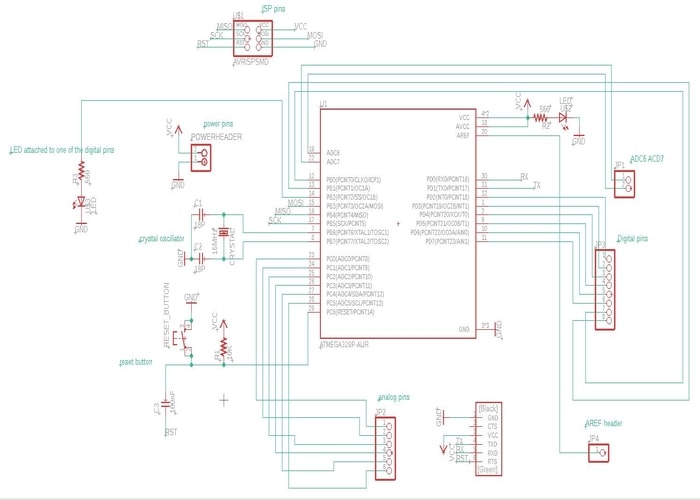
Using this micro-controller I have designed my own Ardunio board. It contains decoupling capacitors, 16MHz external oscillator, LED connected to the VCC, microUSB for power, ISP headers, FTDI cable headers, push button for reset, analog pins and digital pins.
Circuit schematic of the designed ardunio board
The deisnged PCB of my own ardunio board
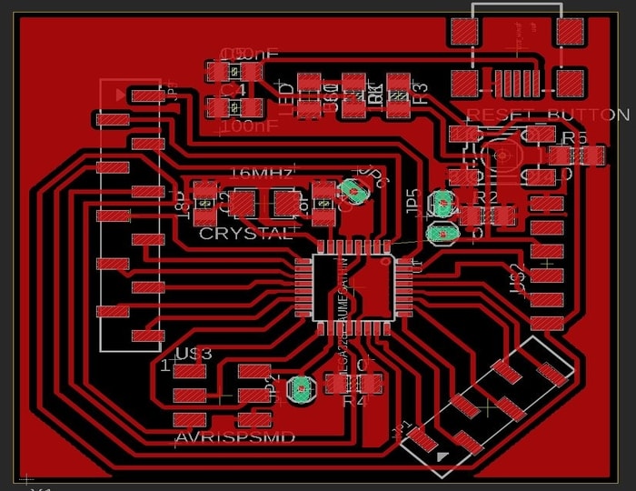
Then, I have exported the board as image and using GIMP I have created the traces file and the outline file for milling
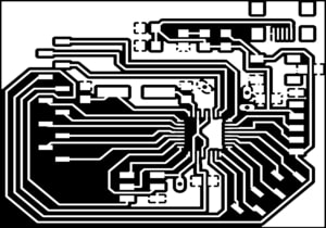
Then, I have used the fab modules to mill the circuit using the milling machine SRM20
.jpg)
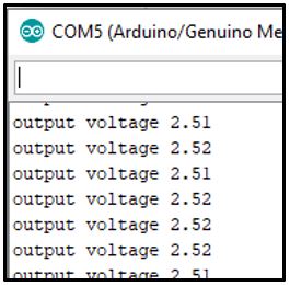
So, after designing and creating the sensor circuit and the micro-conroller circuit, I have connecting them togather and upload the code to get the readings of the sensor. Here is screenshots of the results that I got when testing the sensor. This is when no pressure was applied to the sensor (pressure = 0).
Sensor output voltage when no pressure was applied:
equivalent pressure in PSI:
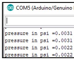
equivalent pressure in Pa:
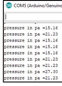
So, this number has been rounded to zero to get 0 pressure when there is no pressure applied.
Flowmeter tube design
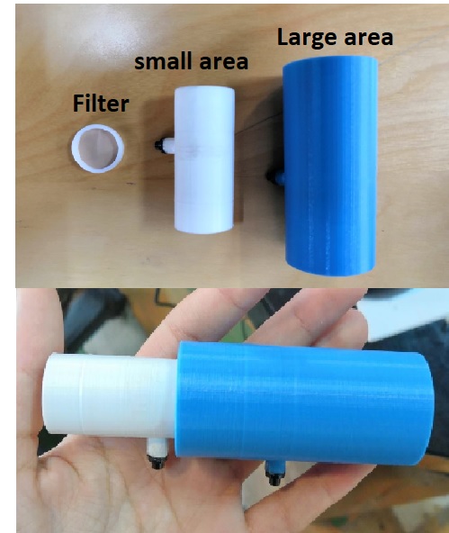
The flowmeter tube was designed using a 3D software called Fusion360 from Autodesk. After the design was made, it has been printed using the 3D printer Prusa i3. The designed tube is a venturi tube and it consist of two areas, large area and throat area. The venturi tube has a shape which allows the air to have a constricted flow. A pressure drop will be developed in the smaller area of the tube (the throat area) while the velocity of the fluid on that area will be increased. Therefore, using Fusion 360, I have designed two saperated parts which can fit togather to build the venturi tube.
Small area of the tube:
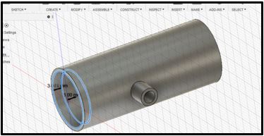
Specifications of the built small area of the tube:
• outer diameter of the tube = 21 mm.
• inner diameter of the tube = 18 mm.
• outer diameter of the connecter = 6mm.
• inner diameter of the connecter = 4mm.
Large area of the tube:
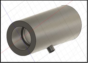
Specifications of the built large area of the tube:
• outer diameter of the tube = 30 mm.
• inner diameter of the tube = 28 mm.
• outer diameter of the connecter = 6mm.
• inner diameter of the connecter = 4mm.
After designing the two tube, I have printed them using the 3D printer:
area1-tube-design from Zahra almukhariq on Vimeo.
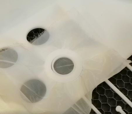
After printing the tubes, I have designed a filter using a silk screen to create more pressure drop in the tube and to ensure a laminar flow it it. This is when I was testing different sizes to perfectly fit inside the tube.
.jpg)
Then, the silk screen has been installed and cut using the laser cutting machine
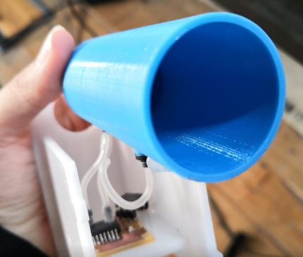
Finally, this is the whole design of the tube aftering adding the black connectors to it which will be connected to the sensor later on to take the reading of the lung volume and air flow rate from the user breathing in the big area of tube.
Tube handle
After designing the tube, I moved to design the handle of it. As mentioned before, the pressure sensor circuit will be connected to the 3D printted tube from both sides. Then the tube and the circuit will be fit in a case (handle) to make it easier for users to hold the tube and use it.
Here is after taking the daimensions and designing the tube in inkscape software
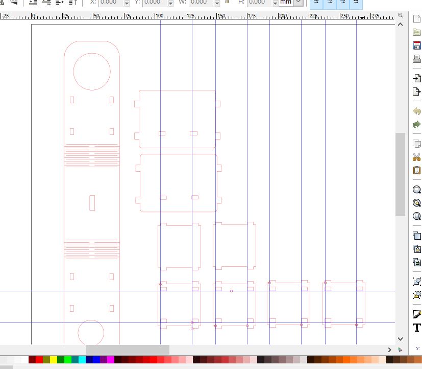
And here the PDF file of it
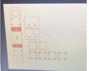
And here is the file showing in task manager ready for cutting
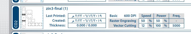
The material used for the handle is Acrylic and I have cut it using the laser cutting machine. But first, I have tested the design with cardboard to make sure that the daimensions are correct. This is shown in the video below:
After testing with cardboard, I noticed that the daimeter of the holes are incorrect (The printed tubes cannot be fit). Therefore, I have edited the design and cut the final one with acrylic as shown in the video below
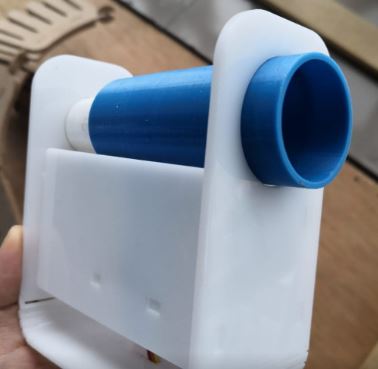
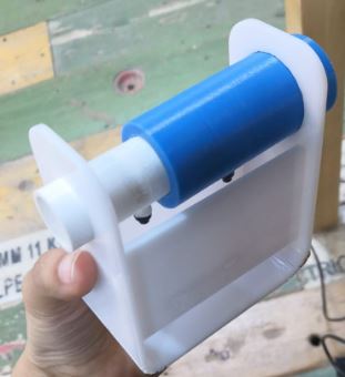
Finally this is the handle after installing the printed tubes and the sensor to it.
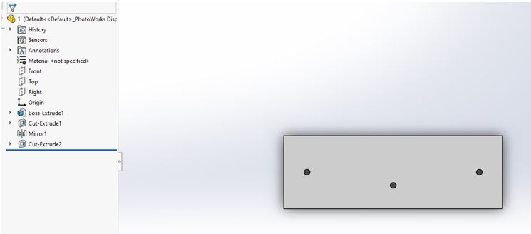
Case of the device (Box design)
steps of designing the box in Solidworks
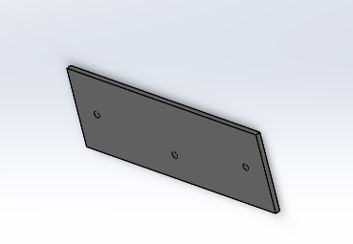
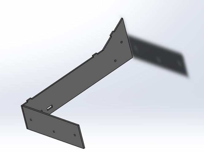
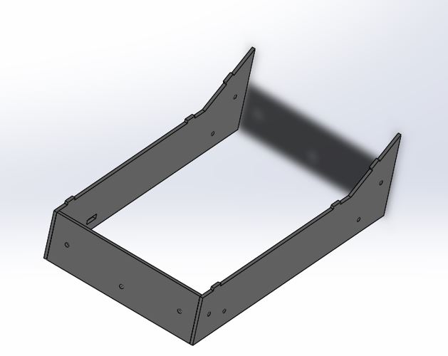
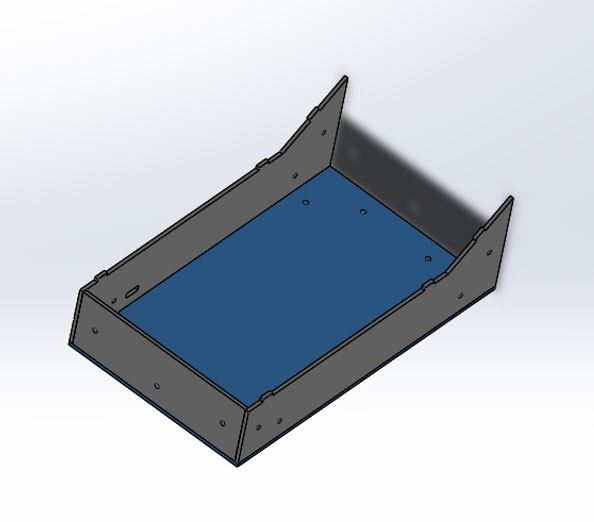
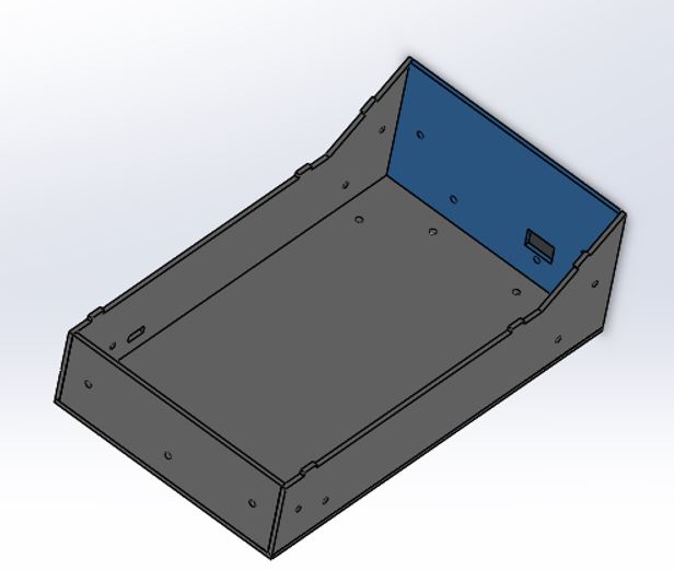
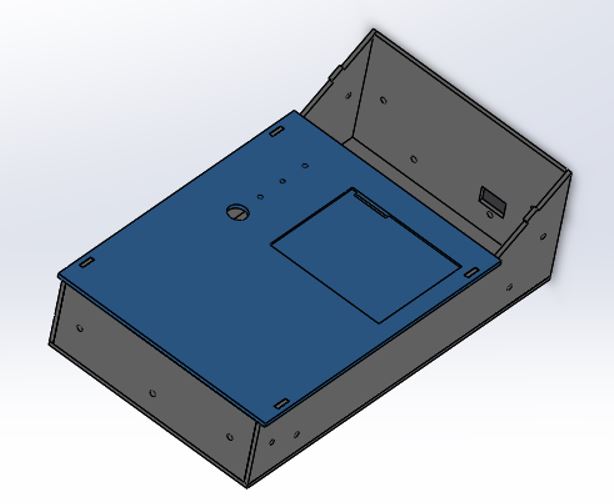
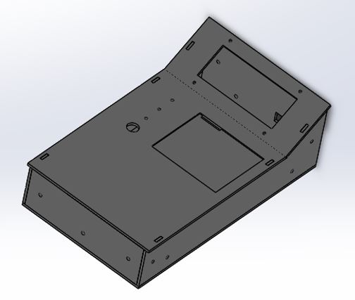
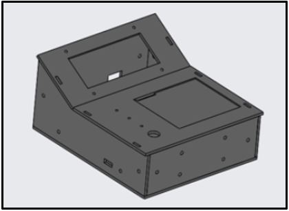
Downlaod the box files (Parts that have been cut using the laser cutting machine after converting the 3D design to 2D)
testing keypad and LCD
The LCD (Liquid Crystal Display) has a blue panel and white LED backlight. It operates at 5 volts power supply and 1.5mA supply current. The voltage at all its input pins is between 2.2 to 5.5 volts. The maximum and LED forward voltage is 3.4V, while the maximum forward current is 20mA. In this project 4x20 LCD has been selected over the 2x16 LCD because it displays more characters. It can be display up to 80 characters as 4 x 20 = 80. To reduce the amount of wires and connections to the microcontroller, I2C communication method was implemented by connecting the LCD pins to I2C LCD serial interface module.
The LCD has been already connected with the I2C module and tested from week 12, please visit the page to view all the detials about the connection.
The purpose of using the LCD in this project is to display the tests menu to the user, to give instructions for users on how to perform the selected test, and to display the test results and data.
Moving to the keypad, 5x4 keypad was used in this project. The 5x4 keypad is a 20-key matrix keyboard. It has 5 rows and 4 columns, so 9 pins from the micro-controller were needed to scan all pads. The keypad was used in this project for users to enter their ID and age, and to select the preferred test to be performed.
Keypad specifications:
• Insulation Resistance:100M Ω 100V.
• Withstand Voltage: 250V Rms. (50-60Hz min).
• Storage Temperature: +15°- +35°.
• Storage Humidity: 70-90.
Both keypad and LCD has been connected to the ATmega328P micro-controller as following:
| LCD pin | ATmega328P |
|---|---|
| GND | GND |
| VCC | 5V |
| SDA | A4 |
| SCL | A5 |
| Keypad pin | ATmega328P |
|---|---|
| row 1 | 10 |
| row 2 | 9 |
| row 3 | 8 |
| row 4 | 7 |
| row 5 | 6 |
| column 1 | 5 |
| column 2 | 4 |
| column 3 | 3 |
| column 4 | 2 |
steps of connection:
1- Connect the lcd to the micro-controller board as mentioned ealier.
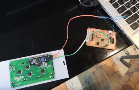
2- Connect the keypad to the micro-controller board as mentioned ealier.
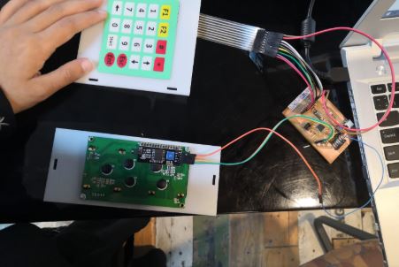
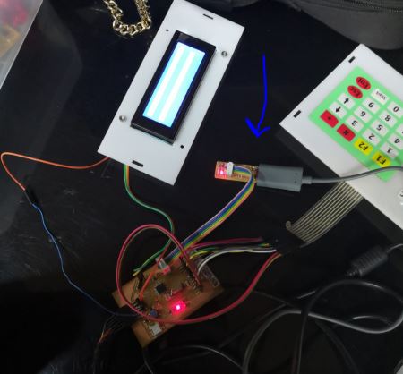
3- Connect the FTDI cable to give power to your board.
4- Connect the programmer to start programmering.
5- Then open Arduino IDE and the following code has been applied:
#include <Keypad.h> //Library used for the keypad
#include <LiquidCrystal_I2C.h> //Library used for the 4x20 LCD
#include <Wire.h> //Library to allow communication with I2C

int counter;

#define I2C_ADDR 0x27 //defining the LCD pins
#define BACKLIGHT_PIN 3
#define En_pin 2
#define Rw_pin 1
#define Rs_pin 0
#define D4_pin 4
#define D5_pin 5
#define D6_pin 6
#define D7_pin 7
//LiquidCrystal_I2C lcd(I2C_ADDR,En_pin,Rw_pin,Rs_pin,D4_pin,D5_pin,D6_pin,D7_pin);

LiquidCrystal_I2C lcd(0x27,20,4); //set the I2C address 0x27 and the LCD used is 4x20

const byte numRows= 5; //number of rows on the keypad
const byte numCols= 4; //number of columns on the keypad
char keyMap[numRows][numCols]=
{
  {'Y', 'N', '#', '*'},
  {'1', '2', '3', 'U'},
  {'4', '5', '6', 'D'},
  {'7', '8', '9', 'S'},
  {'L', '0', 'R', 'E'},

};
byte rowPins[numRows] = {10,9,8,7,6}; //Rows pins
byte colPins[numCols]= {2,3,4,5}; //Columns pins

Keypad keyPad= Keypad(makeKeymap(keyMap), rowPins, colPins, numRows, numCols);

#define data_Length 11
char Data[data_Length]; //set array to store user ID
byte data_count = 0;

void clearData() {
  while (data_count != 0)
  {
    Data[data_count--] = 0;
  }
  return;
}

#define data_Length2 4
char Data2[data_Length2]; //set array to store user age
byte data_count_age = 0;

void clearData2() {
  while (data_count_age != 0)
  {
    Data2[data_count_age--] = 0;
  }
  for (int n = 0; n <= 8; n++) //command for keep displaying the ID on the screen
  {
    lcd.setCursor(n, 1);
    lcd.print(Data[n]);
  }
  return;
}

void setup(){
  Serial.begin(9600);
  lcd.begin();   // initialize the lcd.
  lcd.backlight(); //set backlight on.
}

void loop(){
lcd.setCursor(0, 0);
lcd.print("Enter user CPR:");
lcd.setCursor(0, 2);
lcd.print("Enter user age:");

char customKey = keyPad.getKey();


  //if a button in the keypad pressed, check which one of the following conditions is correct:
  if (customKey) {


    if (customKey == 'E') {
      lcd.setCursor(0, 3);
      counter = counter + 1;
    }

    if ((customKey == '1' || customKey == '2' || customKey == '3' || customKey == '4' || customKey == '5' || customKey == '6' || customKey == '7' || customKey == '8' || customKey == '9' || customKey == '0') && counter == 0) {
      Data[data_count] = customKey;
      lcd.setCursor(data_count, 1);
      lcd.print(Data[data_count]);
      data_count++;
    }
    else
    {
      if ((customKey == '1' || customKey == '2' || customKey == '3' || customKey == '4' || customKey == '5' || customKey == '6' || customKey == '7' || customKey == '8' || customKey == '9' || customKey == '0') && counter == 1) {
        Data2[data_count_age] = customKey;
        lcd.setCursor((data_count_age), 3);
        lcd.print(Data2[data_count_age]);
        data_count_age++;
      }
    }
  }

  if (customKey == 'L' && counter == 0) {
    lcd.setCursor((data_count) - 1, 1);
    lcd.print(" ");
    data_count--;
  }

  if (customKey == 'L' && counter == 1) {
    lcd.setCursor((data_count_age) - 1, 3);
    lcd.print(" ");
    data_count_age--;
  }

}
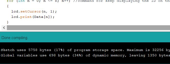
here is after done compiling
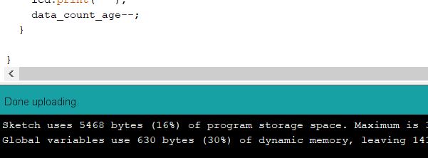
And here is after done uploading
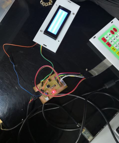
The following video shows that when I pressed buttons in the keypad, it shows in the LCD.
LEDs and Buzzer circuit
Now, after the user enter his/her ID and age, a menu should be displayed of the tested and instruction on how to preform those tests. After that LED and buzzer will go high as indicator for user to start the test and OFF when the start is finished. Therefore, I have coonected LEDs and buzzer on a breadboard and testing them with the keypad and lcd.
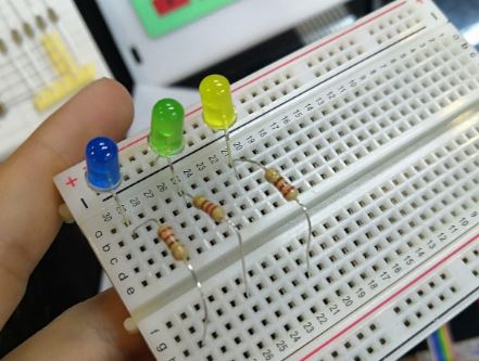
Step 1:
I have connected the LEDs with 220 ohm resistors on a bread board.
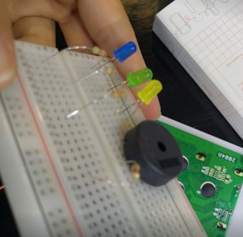
Step 2:
I have connected the Buzzer with 100 ohm resistor and a breadboard.
Step 3:
I have connected the components with the micro-controller board as following.
| Component | ATmega328P |
|---|---|
| LED1 | A3 |
| LED2 | A2 |
| LED3 | 1 |
| Buzzer | 0 |
Step 4:
I have connected the FTDI cable to provide power to the board.
Step 5:
I have connected the programmer to program the board.
Step6:
I have uploaded the following code
#include <Keypad.h> //Library used for the keypad
#include <LiquidCrystal_I2C.h> //Library used for the 4x20 LCD
#include <Wire.h> //Library to allow communication with I2C

int counter;
char customKey;
const int buzzer = 0;
int clearscreen = 0;
int Invalid_ID;
String frame = "------------------";
int runningTest_LED = 1;
int FEV1_LED = A3;
int MVV_LED = A2;
int KeepOn1=0;
int KeepOn2=0;

#define I2C_ADDR 0x27 //defining the LCD pins
#define BACKLIGHT_PIN 3
#define En_pin 2
#define Rw_pin 1
#define Rs_pin 0
#define D4_pin 4
#define D5_pin 5
#define D6_pin 6
#define D7_pin 7
//LiquidCrystal_I2C lcd(I2C_ADDR,En_pin,Rw_pin,Rs_pin,D4_pin,D5_pin,D6_pin,D7_pin);

LiquidCrystal_I2C lcd(0x27,20,4); //set the I2C address 0x27 and the LCD used is 4x20

const byte numRows= 5; //number of rows on the keypad
const byte numCols= 4; //number of columns on the keypad
char keyMap[numRows][numCols]=
{
  {'Y', 'N', '#', '*'},
  {'1', '2', '3', 'U'},
  {'4', '5', '6', 'D'},
  {'7', '8', '9', 'S'},
  {'L', '0', 'R', 'E'},

};
byte rowPins[numRows] = {10,9,8,7,6}; //Rows pins
byte colPins[numCols]= {2,3,4,5}; //Columns pins

Keypad keyPad= Keypad(makeKeymap(keyMap), rowPins, colPins, numRows, numCols);

// ............................................................................ ALARM OF INVALID INPUTS ..........................................................................................//

void invalid_input_alarm() {
tone(buzzer, 1000); //turn alarm on by sending 1KHz sound signal (the tone function is contolled by timer3 in the arduino)
  delay(1500);        //keep the sound on for 1 sec
  noTone(buzzer);     //Stop sound
  delay(4000);        //wait for 4 scond for the user to read the message from the lcd
  lcd.clear();        //after 4 seconds clear the lcd
}
// ............................................................................ ID array ..........................................................................................//
#define data_Length 11
char Data[data_Length]; //set array to store user ID
byte data_count = 0;

void clearData() {
  while (data_count != 0)
  {
    Data[data_count--] = 0;
  }
  return;
}

// ............................................................................ age array ..........................................................................................//

#define data_Length2 4
char Data2[data_Length2]; //set array to store user age
byte data_count_age = 0;

void clearData2() {
  while (data_count_age != 0)
  {
    Data2[data_count_age--] = 0;
  }
  for (int n = 0; n <= 8; n++) //command for keep displaying the ID on the screen
  {
    lcd.setCursor(n, 1);
    lcd.print(Data[n]);
  }
  return;
}

// ................................................................................................. SUBROUTINE OF THE KEYPAD CONDITIONS WHEN ENTEING ID & AGE ...............................................................................................//

void kepad_conditions1() {

  customKey = keyPad.getKey(); //reading the keypad inputs

  //if a button in the keypad pressed, check which one of the following conditions is correct:
  if (customKey) {

    if (customKey == 'E') {
      lcd.setCursor(0, 3);
      counter = counter + 1;
      tone(buzzer, 5);     //turn alarm on by sending 5Hz sound signal (the tone function is contolled by timer3 in the arduino)
      delay(100);          //keep the sound on for 100 ms
      noTone(buzzer);      //Stop
    }

    if ((customKey == '1' || customKey == '2' || customKey == '3' || customKey == '4' || customKey == '5' || customKey == '6' || customKey == '7' || customKey == '8' || customKey == '9' || customKey == '0') && counter == 0) {
      Data[data_count] = customKey;
      lcd.setCursor(data_count, 1);
      lcd.print(Data[data_count]);
      data_count++;
    }
    else
    {
      if ((customKey == '1' || customKey == '2' || customKey == '3' || customKey == '4' || customKey == '5' || customKey == '6' || customKey == '7' || customKey == '8' || customKey == '9' || customKey == '0') && counter == 1) {
        Data2[data_count_age] = customKey;
        lcd.setCursor((data_count_age), 3);
        lcd.print(Data2[data_count_age]);
        data_count_age++;
      }
    }
  }

  if (customKey == 'L' && counter == 0) {
    lcd.setCursor((data_count) - 1, 1);
    lcd.print(" ");
    data_count--;
  }

  if (customKey == 'L' && counter == 1) {
    lcd.setCursor((data_count_age) - 1, 3);
    lcd.print(" ");
    data_count_age--;
  }

  if ((data_count == data_Length - 1) || (data_count < 9 && counter == 1)) {
    lcd.clear();
    lcd.setCursor(2, 0);
    lcd.print("*  Invalid ID  *");
    lcd.setCursor(7, 1);
    lcd.print("only 9");
    lcd.setCursor(2, 2);
    lcd.print("values accepted");
    invalid_input_alarm(); //calling the alaram function
    clearData(); //calling the function to clear the data (ID array)
    counter = 0;
  }

  if ((data_count_age > 3)) {
    lcd.clear();
    lcd.setCursor(3, 1);
    lcd.print("* Invalid age *");
    lcd.setCursor(4, 2);
    lcd.print("re-enter age");
    invalid_input_alarm(); //calling the alarm function
    clearData2(); //calling the function to clear the data (Age array)
  }
}

// ................................................................................ SUBROUTINE OF THE INSTRUCTIONS THAT WILL DISPLAY ON THE LCD WHEN A TEST CHOSE FROM MENU...................................................................................//

void kepad_conditions2() {

    customKey = keyPad.getKey(); //reading the keypad inputs
    //if a button in the keypad pressed, check which one of the following conditions is correct:
    if (customKey){
    clearscreen=1;
    if (customKey == '1'){ //give the user instructions on how to do the FVC and FEV1 tests.
    lcd.clear();
    lcd.setCursor(0,0);
    lcd.print("Take a deep breathe");
    lcd.setCursor(0,1);
    lcd.print("then exhale as much");
    lcd.setCursor(0,2);
    lcd.print("& as fast as you can");
    lcd.setCursor(0,3);
    lcd.print("READY? press<start>");
    if (customKey == '1' or KeepOn1 == 1){
    digitalWrite (FEV1_LED, HIGH);
    KeepOn1 = 1;
    }
    }

    if (customKey == '2'){ ////give the user instructions on how to do the MVV test.
    lcd.clear();
    lcd.setCursor(0,0);
    lcd.print("Breathe deeply and");
    lcd.setCursor(0,1);
    lcd.print("rapidly for 15 sec");
    lcd.setCursor(0,3);
    lcd.print("READY? press start");
    if (customKey == '2' or KeepOn2 == 1){
    digitalWrite (MVV_LED, HIGH);
    KeepOn2= 1;
    }
    }

    if (customKey == 'R' && KeepOn1 == 1)
    {
      counter = 5;
    }

    if (customKey == 'R' && KeepOn2 == 1)
    {
      counter = 6;
    }
}
}

// ............................................................................ void setup ..........................................................................................//

void setup(){
 pinMode(buzzer, OUTPUT); // Set buzzer as an output
  pinMode(runningTest_LED, OUTPUT); // Set the LEDs as an output
  pinMode(FEV1_LED, OUTPUT);
  pinMode(MVV_LED, OUTPUT);
  Serial.begin(9600);
  lcd.begin();   // initialize the lcd.
  lcd.backlight(); //set backlight on.
  lcd.setCursor(1, 0); //set the cursor to this position
  lcd.print(frame); //print the string
  lcd.setCursor(1, 1); //set the cursor to this position
  lcd.print("|   Spirometer   |"); //print the follwing
  lcd.setCursor(1, 2); //set cursor to this posution
  lcd.print("|     project    |"); //print the following
  lcd.setCursor(1, 3);  //set the cursor to this position
  lcd.print(frame); //print the string
  delay (4000); //wait 4 sec
  lcd.clear(); //then clear the lcd
}

// ............................................................................ void loop ..........................................................................................//

void loop(){

  if (counter == 0 or counter == 1)  //user enter ID and age.
  {
    lcd.setCursor(0, 0);
    lcd.print("Enter user CPR:");
    lcd.setCursor(0, 2);
    lcd.print("Enter user age:");
    kepad_conditions1();
  }

  if (counter == 2) //displaying test time and date for the user.
    if (clearscreen == 0)
      {
      lcd.setCursor(0, 0);
      lcd.print("Chose type of test:");
      lcd.setCursor(0, 1);
      lcd.print("1) FVC & FEV1");
      lcd.setCursor(0, 2);
      lcd.print("2) MVV");
      }
 }
This video below shows when the code was testing. It shows that the buzzer goes high when the user entered invalid ID. Also, a message will be shown on the screen to tell the user that the ID in not eccepted. The user can clear charecters and re-enter values using the backward arrow.
Then, after making sure that everthings is working as expected. I have connected the sensor and testing all the system togather. This is showing in the video below:
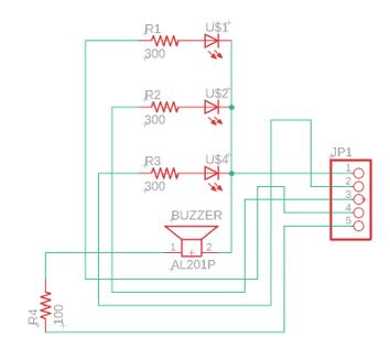
Finally, I have created a PCB for the LEDs and buzzer which will be fit in the box that I have designed ealier. For designing the circuit, I have used eagle software from Autodesk. I started with the schematic by placing the compponents and do the wiring. The figure below shows the schematic:
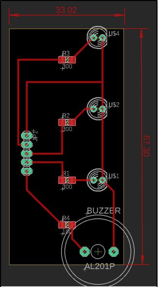
After the schematic, I moved to the PCB design. The figure below shows how I had designed the PCB of the LEDs and buzzer as well as the size of the board:
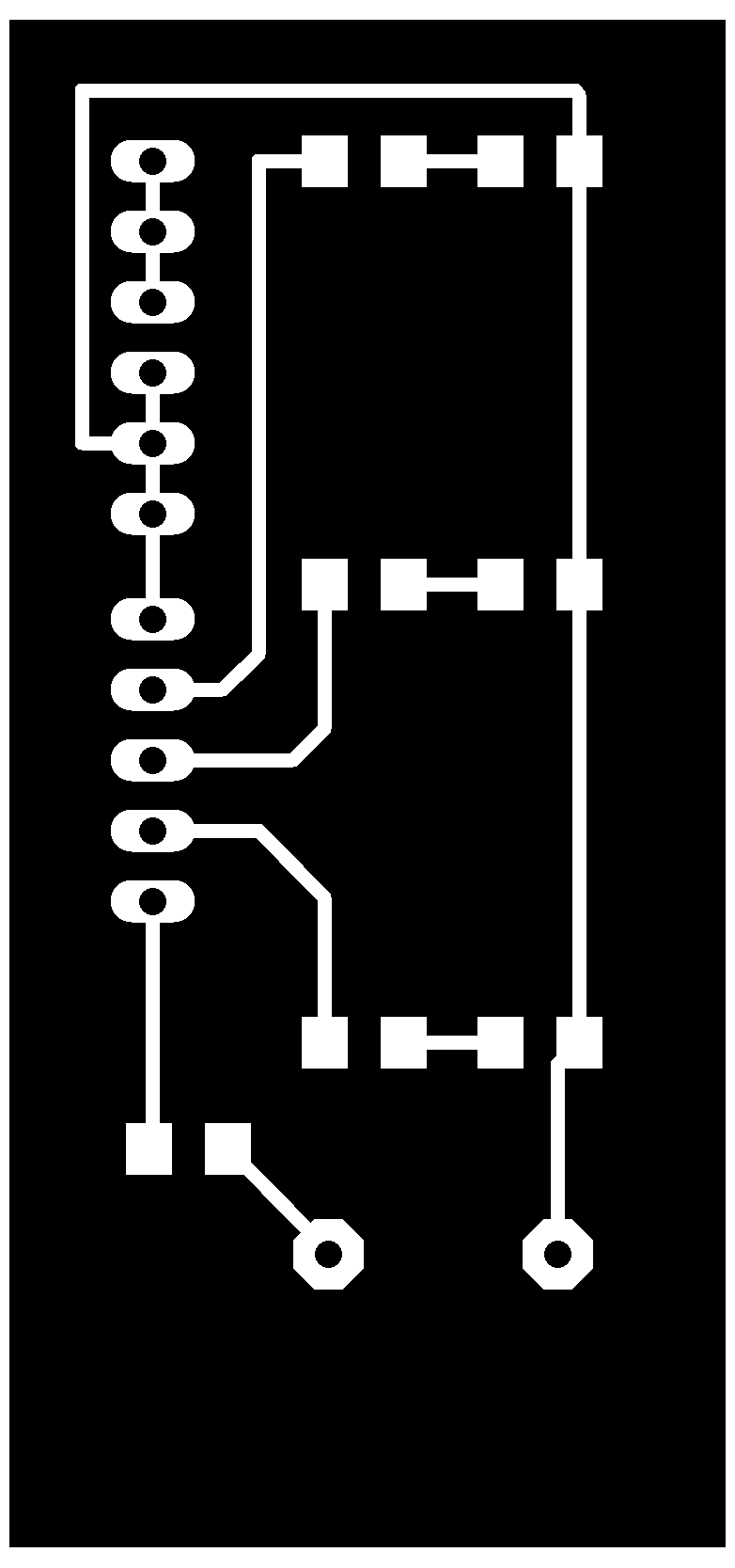
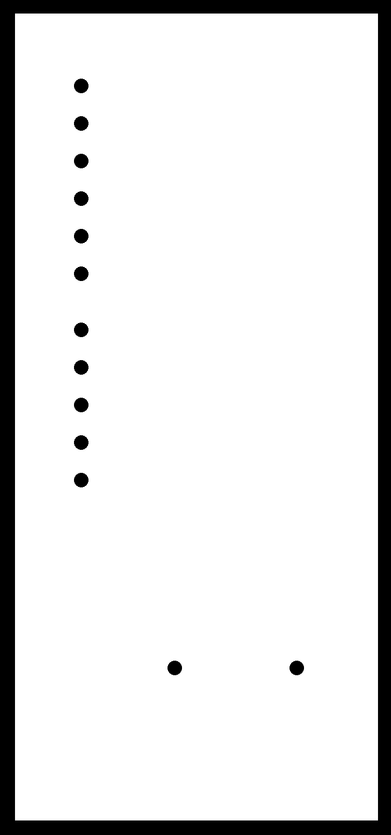
Next I have saved the design as png and in GIMP software I have prepare the traces file and the outline file like is showing below:
After that, in FabModules I have imported those files and get the rml files that will be used to mill the circuit in SRM20 milling machine.
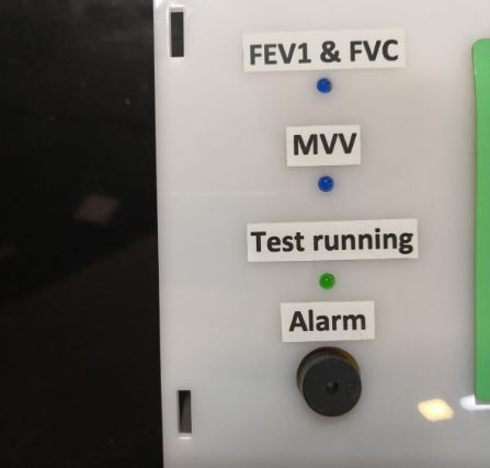
The picture below shows the ciruit after I haved soldered the components and fixed the board on the box. I have also made a stickers to present what each LED represent.
Materials & machines
All material used in this project are listed here:
| Component | Price | Supplier | Description |
|---|---|---|---|
| Atmel AVR microcontroller | - | Digi-key | Atmega328P |
| Pressure sensor | $44.71 | Farnell UK | Differentail pressure sensor NPA500B10WD |
| LCD | $18 | ElectronicsWaves - KSA | 4x20 LCD |
| RTC module | $1.79 | Dr.Processor - Bahrain | DS1302 |
| Silicon tubes | - | Bahrain shops | about 1/4 meter |
| Keypad | $6.65 | ElectronicsWaves - KSA | 4x5 keypad |
| LEDs | $0.8 | - | Three LEDs |
| Buzzer | $1 | Dr.Processor - Bahrain | - |
| Power bank | $13 | Bahrain markets | 5v output |
| Miscellaneous | - | - | Resistors, Capacitors, etc |
| Acrylic sheet | $70 | - | 4ft x 8ft |
| PLA filament | $35 | - | - |
Mashines used:
1- 3D printer
2- Laser cutting machine
3- Milling machine
4- Soldering iron
Final look of the device
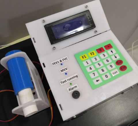
All parts have been assemble togather and here is the final product
Download files
Schematic of my own micro-controller board here.
PCB of my own micro-controller board here.
Schematic of the LEDs and buzzer circuit here here.
PCB of the LEDs and buzzer circuit here here.
3D design of the box here.
Tube handle design here.