14. Networking and communications
Objectives of this week are:
1- To design, build, and connect wired or wireless node(s) with network or bus addresses.
Group assignment
To view the group page, click on the link here.
I2C
For this week, the hello world circuit was connected with the designed Ardunio circuit through I2C communication (Inter-Integrated Circuit). The schematic below explained the I2C communication.

I2C combines the features of SPI and UARTs. I2C gives the ability to connect multiple slaves to a single master (like SPI), and the ability to have multiple masters controlling single, or multiple slaves. This is useful when we want to have more than one microcontroller logging data to a single memory card or displaying text to a single LCD. I2C uses only two wires to transmit data between devices which are the data line (SDA) and the clock line (SCL). I2C is a serial communication protocol, so data is transferred bit by bit along a single wire (SDA line), while the SCL line carries the clock signal.
master board
My master board for this assignment is the hello-world board that I have worked on it in week7. This board contains a push button that will controll an LED of the slave board. The code and connection are mentioned below:
Using my programmer and the FTDI cable I have connected the master board with my computer to program the circuit and upload the code in it. The connection:

Code:
#include <SoftwareSerial.h>
#include <Wire.h>

#define button 3

void setup() {
Wire.begin();
pinMode(button, INPUT_PULLUP);
}
void loop() {
int button_data;
button_data = digitalRead(button);
if (button_data == 1)
{
Wire.beginTransmission(8);
Wire.write(1);
Wire.endTransmission();
}
else {
Wire.beginTransmission(8);
Wire.write(0);
Wire.endTransmission();
}
}
slave board
My slave board for this assignment is the Ardunio board that I have designed and built in week11. I have connected an LED to the digital pin 4 of this board, so using the push button of the hello-world circuit, I am controlling the LED in my own Ardunio circuit. The code and connection are mentioned below:
Using my programmer and the FTDI cable I have connected the slave board with my computer to program the circuit and upload the code in it. The connection:

Code:
#include <Wire.h>
#define led 4
void setup() {
Wire.begin(8);
Wire.onReceive(receiveEvent);
pinMode(led, OUTPUT);
}
void loop() {
delay(100);
}
void receiveEvent(int howMany) {
int x = Wire.read();
if (x == 1)
{
digitalWrite(led, HIGH);
}
if (x == 0)
{
digitalWrite(led, LOW);
}
}
outcome
The video below shows the result. I was able to control the LED in my own Ardunio board using the push button in the hello-world circuit through I2C communication. The connection have been made like the schematic mentioned above using 4.7K resistors. The VCC and GND of both boards were connected togather as well.
Wireless communication (Bluetooth)
overview
Another communication method that I have tested this week is the wireless communication via Bluetooth. I am going to use two bluetooth modules. One will be connected to the hello world board while the other will be connected to the main board (my own arduino board that I have designed, built and tested in week 14). By pressing on the push button on the hello world circuit, an LED will be controlled (turned oFF and ON) in the main circuit. The data will be transmitted wirelessly via the bluetooth modules.
The Bluetooth module that I am using this week is the same of Bluetooth module that I used in week 16 which is HC-05. Here is some of the features about this module:
• Supply voltage = 4V to 6V (Typically +5V).
• Communication method = Serial communication.
• Operating current: 30mA.
• Range = <100 m.
• Supported baud rate: 9600,19200,38400,57600,115200,230400,460800.
To view the full features and spesifications, please refer to the datasheet here.
The HC-05 Bluetooth module provides switching mode between master & slave mode. Thats mean it can be used either for receiving data or for transmitting data. The general connection of the bluetooth module with ATmega328P can be shown in the figure below:
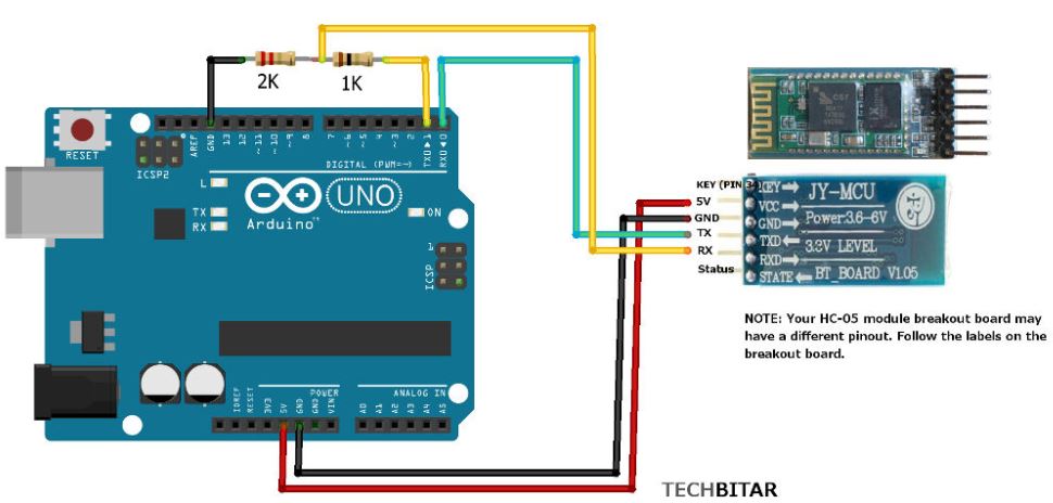
As you can see, there is a voltage divider circuit in the connection. This is becuase that the TX & RX pins operate on a 3.3 volts. Therefore, by connecting the RX pin directly to my main circuit, there will be chance for module to be damaged. Therefore, to aviod this problem, voltage divider ciruit will be added with resistor values of 1K and 2K ohms.
workflow
AT mode
To start working, we first need to indentify which is the salve and which is the master for our bluetooth modules. So in order to achive that, I have configure both modules to AT Command Mode. I have connected the bluetooth module to an Arduino Uno board as following:
| Bluetooth module pin | Arduino Uno pin |
|---|---|
| VCC | 3.3v |
| GND | GND |
| RX | 11 |
| TX | 10 |
| EN | 5v |
Before connecting the Arduino board to the USB cable and to the PC, we must remove the VCC wire from the HC-05. Then, upload the following code to Arduino Uno:
#include <SoftwareSerial.h>

SoftwareSerial BTSerial(10, 11); // RX | TX

void setup()
{
  pinMode(9, OUTPUT);  // this pin will pull the HC-05 pin 34 (key pin) HIGH to switch module to AT mode
  digitalWrite(9, HIGH);
  Serial.begin(9600);
  Serial.println("Enter AT commands:");
  BTSerial.begin(38400);  // HC-05 default speed in AT command more
}

void loop()
{
  // Keep reading from HC-05 and send to Arduino Serial Monitor
  if (BTSerial.available())
    Serial.write(BTSerial.read());

  // Keep reading from Arduino Serial Monitor and send to HC-05
  if (Serial.available())
    BTSerial.write(Serial.read());
}


After uploading, connect back the VCC wire to the HC-05. You will notice that the LED of the HC-05 bluetooth module start blinking. This indicates that the bluetooth module has entered AT mode.
To check that everythings is right, open the serial monitor and do the following change:

Then, write “AT” and press enter, you will recevice the following:

Slave Configuration
This pdf file has helped me in the configuration. The steps as following:
1- open the serial monitor
2- Write “AT+RMAAD” and click on send. This will clear any paired devices.
3- Write “AT+ROLE=0” and click on send. This will set the module as slave.
4- Write “AT+ADDR” and click on send. This will get the address of this HC-05. Remember this address as you will need it in master configuration.

5- Write “AT+UART=38400,0,0” and click on send. This is to fix the baud rate at 38400.
6- Write “AT+NAME=HC-05-1\r\n” and click on send. This will renamed the slave bluetooth module to “HC-05-1”
Master Configuration
The steps are as following:
Bring the other bluetooth module and connect it to the ardunio board as explained before. Upload the code and then;
1- open the serial monitor
2- Write “AT+RMAAD” and click on send. This will clear any paired devices.
3- Write “AT+ROLE=1” and click on send. This will set the module as master.
4- Write “AT+CMODE=0” and click on send. This to connect the module to the specified Bluetooth address and this Bluetooth address can be specified by the binding command.
5- Write “AT+BIND=98d3,41,fd4302” and click on send. This is the slave address.
6- Write “AT+UART=38400,0,0” and click on send. This is to fix the baud rate at 38400.
6- Write “AT+NAME=HC-05-2\r\n” and click on send. This will renamed the slave bluetooth module to “HC-05-2”
As you can see in the picture below all went right:

connection and programming
I have connected the hello world circuit to my PC and upload the following code:
Note: since I am using the micro-controller Attiny44, I have changed the board from Tools > Board > ATtiny24/44/84. I have changed the processor to ATtiny 44 and the clock to external 20 MHz.
Then I have compile and upload this code
#include<SoftwareSerial.h>

//softwareSerial mySerial(Rx, Tx);
SoftwareSerial mySerial(PA1, PA0);

#define button PA3

int state = 0;
int buttonState = 0;

void setup() {
  pinMode(PA3, INPUT_PULLUP);
  mySerial.begin(38400); // Default communication rate of the Bluetooth module
}
void loop() {
 if(mySerial.available() > 0){ // Checks whether data is comming from the serial port
    state = mySerial.read(); // Reads the data from the serial port
 }

 // Reading the button
  buttonState = digitalRead(button);
 if (buttonState == LOW) {
   mySerial.write('1'); // Sends '1' to the master to turn on LED

 }
 else {
   mySerial.write('0');

 }

}
Here is after done the uploading without any errors

Then moving to the master circuit, I have connected the main board to my PC through the programmer and the FTDI cable like this:
Then, I have compiled and uploaded the following code
#include<SoftwareSerial.h>

SoftwareSerial mySerial(PD0, PD1);

//LED is connected to GPIO 5
#define led1 PD5

int state = 0;
void setup() {
  pinMode(led1, OUTPUT); //set LED as output
  digitalWrite(led1, LOW);
  mySerial.begin(38400); // Default communication rate of the Bluetooth module
}
void loop() {
 if(mySerial.available() > 0){ // Checks whether data is comming from the serial port
    state = mySerial.read(); // Reads the data from the serial port
 }
 // Controlling the LED
 if (state == '1') {
  digitalWrite(led1, HIGH); // turn LED ON
  state = 0;
 }
 else if (state == '0') {
  digitalWrite(led1, LOW); // turn LED OFF
  state = 0;
 }
}
The code has been uploaded without any errors.

Note that the micro-controlled used in my main circuit is the ATmage328P. So from tool > board > I have chosen “Arduino Uno” since that the micro-controller ATmega328P is the same micro-controller used in arduino uno board.
After that, on a breadboard I have connected the salve circuit with the bluetooth module as well as the voltage divider circuit:
I have used the Arduino Uno just to give power to my circuit and to the Bluetooth module.

Also, I have connected the master board with an LED, bluetooth module and voltage divider circuit. It is showing below:
Here I give directly the power from the FTDI cable.

By providing power to both circuits, I was able to controll the LED of the main circuit by using the button of the hello world circuit. This is shown in the video below: