10. Molding and casting
This week is all about Molding and Casting.
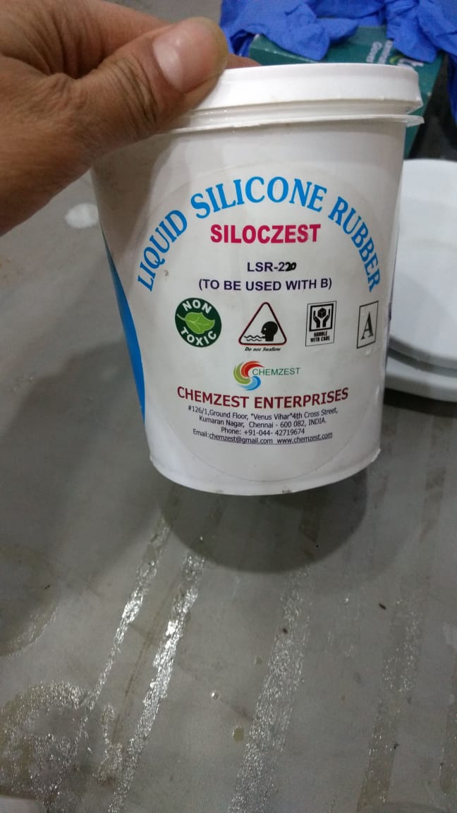
group assignment: review the safety data sheets for each of your molding and casting materials, then make and compare test casts with each of them
individual assignment: design a mold around the stock and tooling that you’ll be using, mill it (rough cut + (at least) three-axis finish cut), and use it to cast parts
Research
According to what i got to know is that Both the process is very similar in which molten material is poured in to the close mold / die which will take the shape of the cavity of close mold and then it cured and removed from the mold.
The basic difference is the method of pouring the material in to the mold. In moulding it will be poured under pressure and in most of the casting process, it does not require any external force to pour the material as the molten material has very less viscosity and is capable to flow with its gravitational force only.
In moulding process the output is the final finished part but in most of the casting process, the output is unfinished part that required the final finishing(machining).
You can also compare injection moulding process and die casting process here.
I went through various websites but as usual one of the most reliable site i found is this. Also, I have mentioned the used links below this.
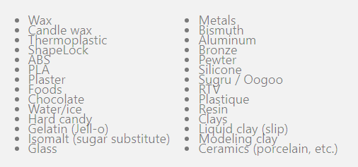
Material (mold making and casting)
There is an absolutely huge list of materials that can be used with the various mold-making and casting techniques out there.
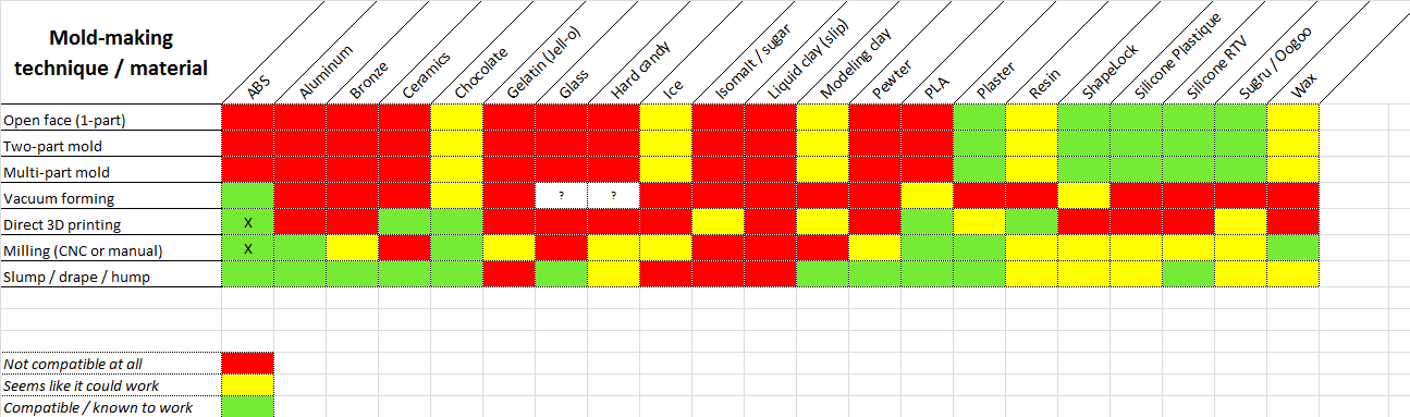
Mold making techniques with different materials
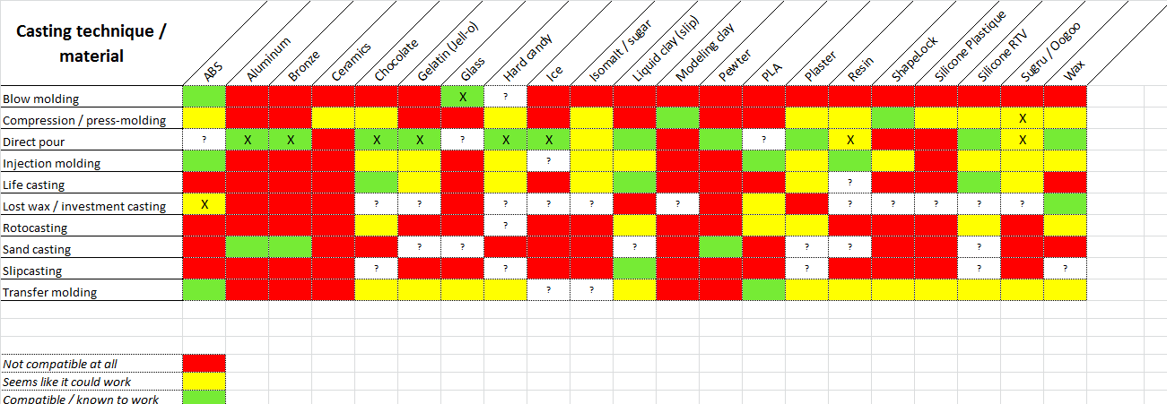
Casting techniques with different materials
Useful links
-mold making and casting techniques and materials
Designing

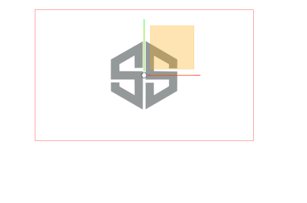
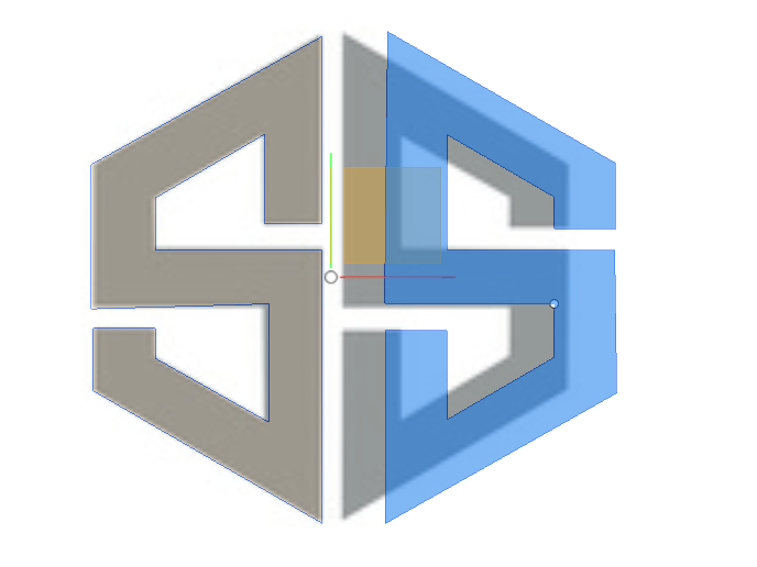
This is the initials “SS” i tried to design on Fusion 360 for this week assignment.
open a new Fusion 360 file. From the Insert dropdown menu, choose Attached Canvas. Select the “bottom” plane for placing your image. A popup window will appear where you can navigate to your image file to upload it. You can translate, rotate, and resize your image using the controls that appear near the image. Be sure to set the sizing and placement of your image right now, because it’s more difficult to do it later. You can also reduce the opacity of your tracing image, which will make it easier to see the sketches you draw on top. Click OK from the Attached Canvas popup window when you’re done.
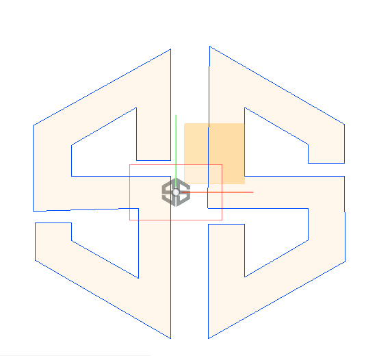
Now, we will trace the image for that open the Sketch dropdown menu and choose Create Sketch with Bottom Plane. The line tool is easiest way to trace any image, Just select the line tool, click on your starting vertex, then click on the location of a new vertex, then another, and so on.
NOTE : When you want to connect with an arc instead of a line, click and drag the previous vertex to create a curved arc; move your mouse around until the arc looks the way that you want it to, then let go to create the new point. Here’s what it looked like after we used the Line tool repeatedly to trace the outside and one of the inside boundaries of the SS logo. Notice that we aren’t always exactly on the lines from the reference image, and in particular that we simplified some of the more complicated parts of the bottom outside boundary of the logo. When you’re done tracing, press the Stop Sketch button from the top menu.
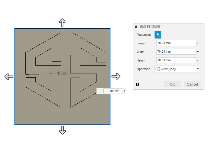
Scaled it to 10mm size for the mould.
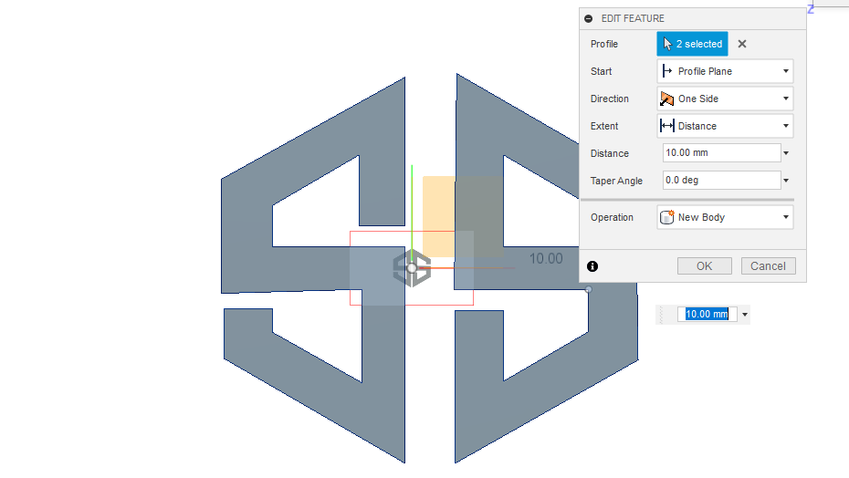
Now select the part of the image you want to extrude upwards. Use Shift-Select if you want to select multiple things. Choose the Create dropdown menu and select Extrude or you can cimply press E for the same, then pull the blue arrow or type a Distance to set the amount of extrusion, and click OK.
You can see that 10mm is used for extruding it.
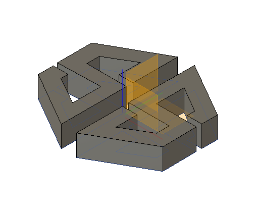
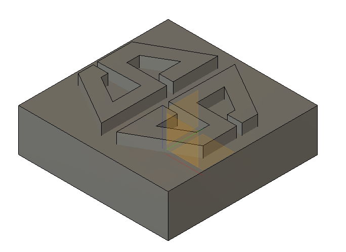
Now, we will make a square from the Create menu of the mentioned dimensions below for the base of mold and place it accurately for SS logo.
Now select both traced logo and square to extrude and join so it comes like this
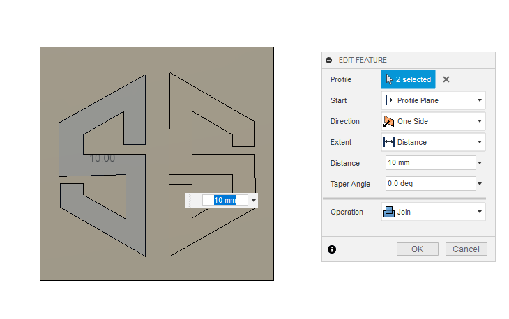
We have to combine the box and the logo so that it becomes one same. The combine option can be found in the Modify section.

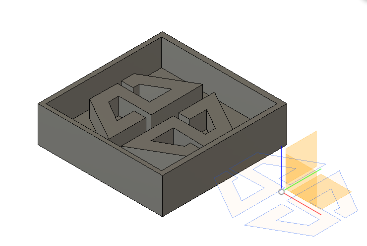
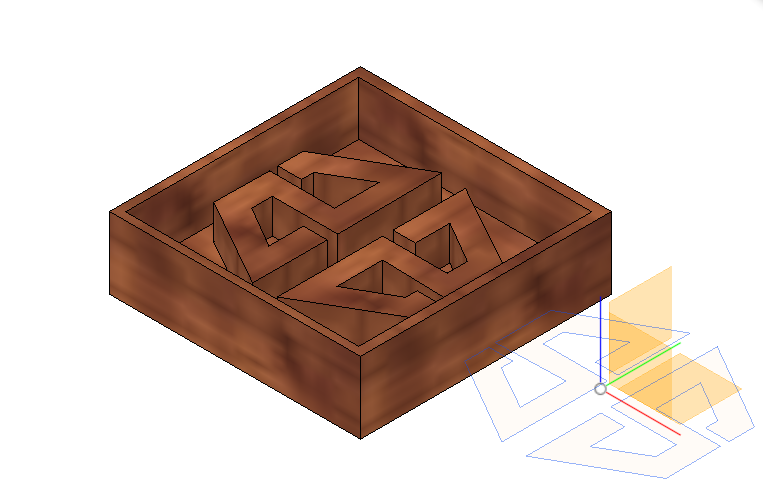
Here is how the final Design will look like this
Milling ToolPath
To begin with the milling we need to have Modela software to Create ToolPaths.
Mold files to be imported :
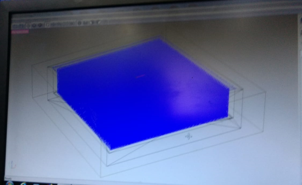
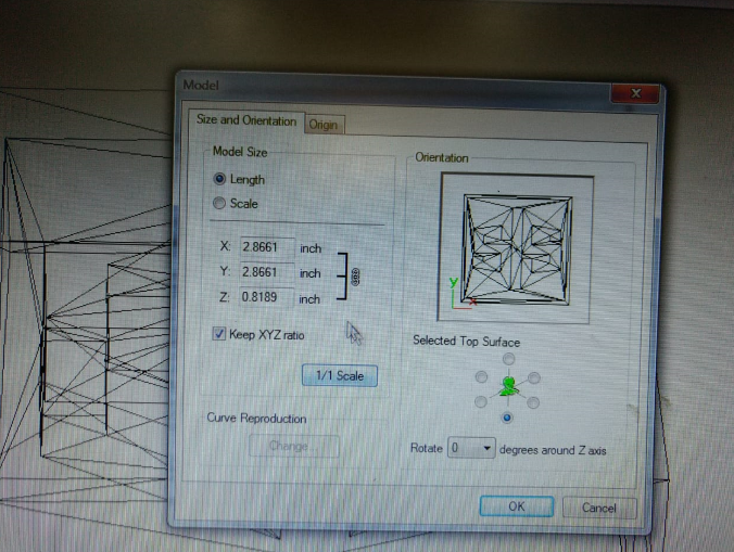
you can make changes in size, orientation and origin.
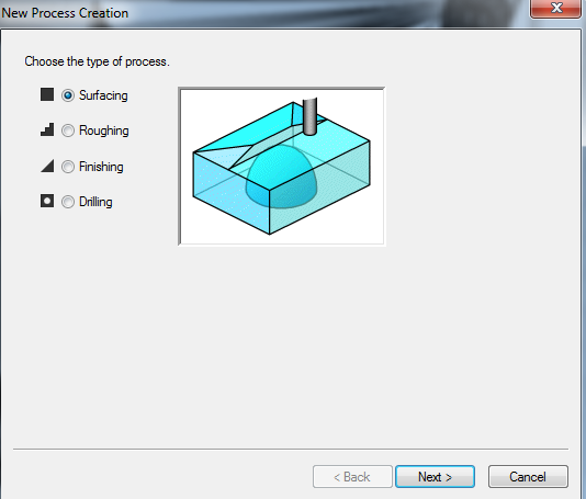
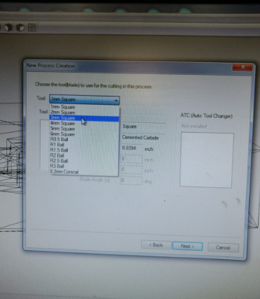
We have to create process and select Roughing and press next.
Now, select the tool from various options in the list. In my case it was 4mm .
Select the cutting area in order to get the mold out.
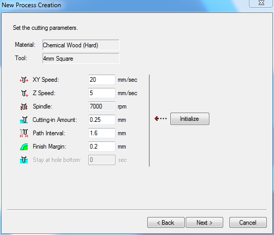
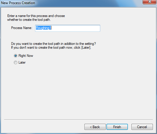
Cutting parameters should be set and press Next. You can see process name edit if you want and press Finish
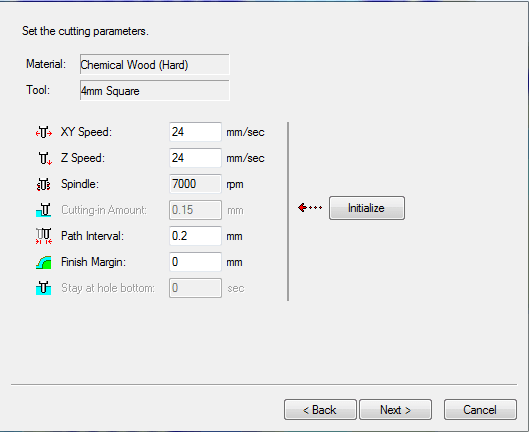
Again Create New Process this time for Finishing

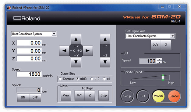
This is the Vpanel SRM-20 using this we need to set the origins and related settings.
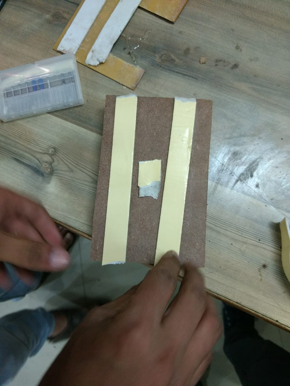
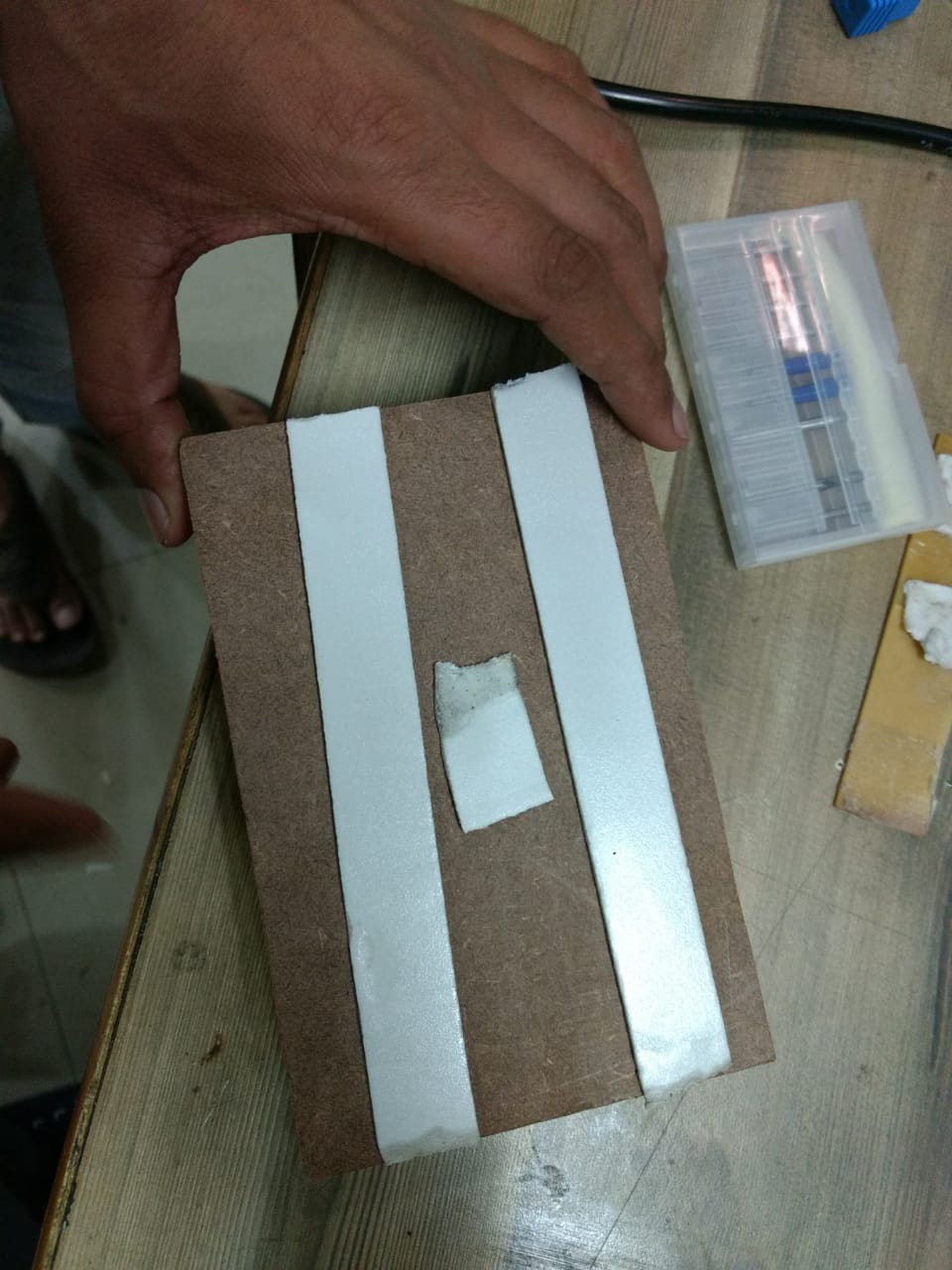
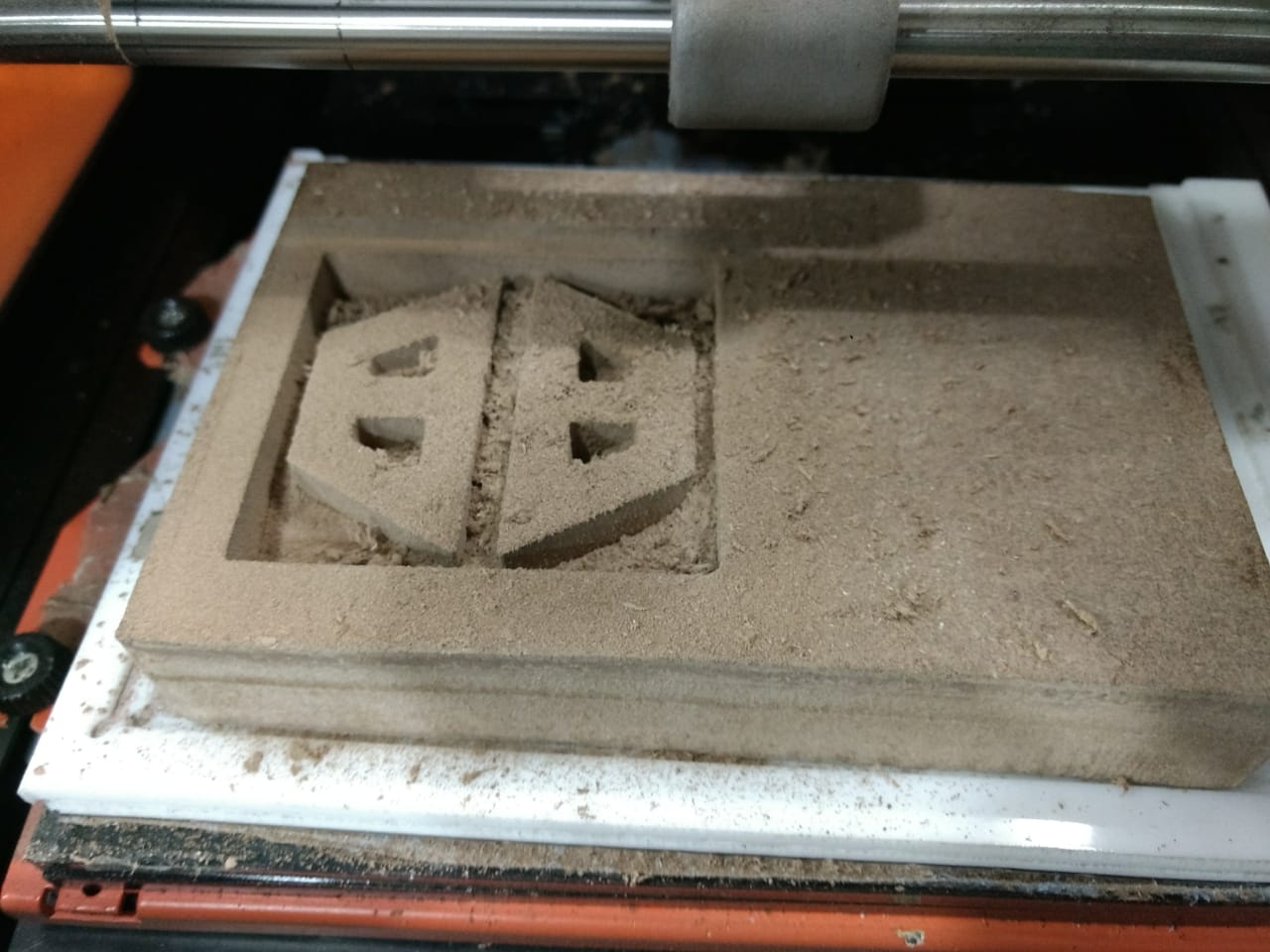
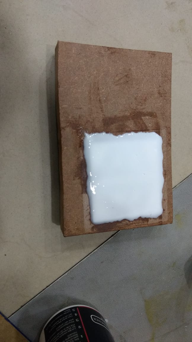
We will now take the chemical wood (hard). Apply some double sided tape to fix it on the surface.
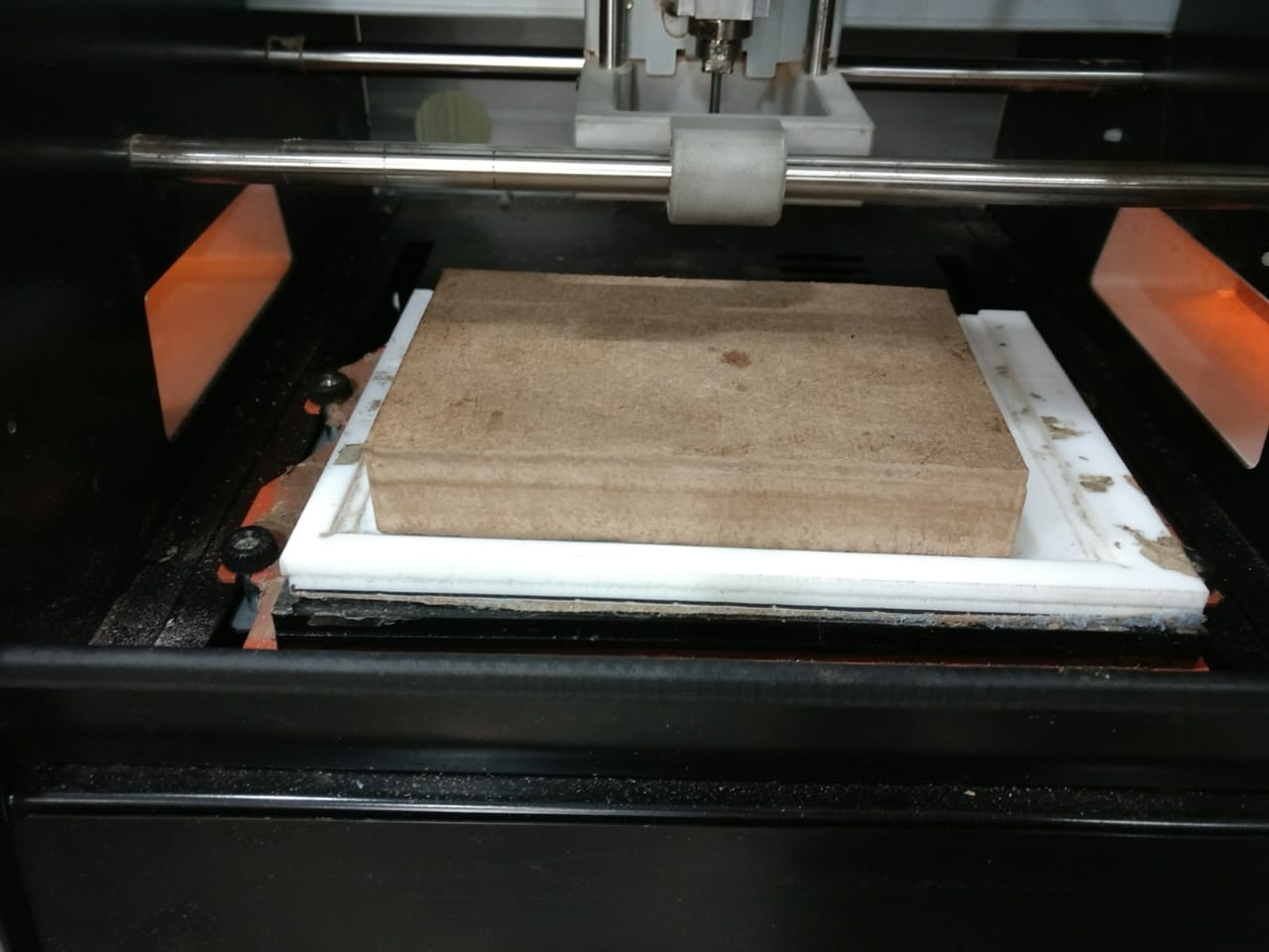
Place the wooden piece in the machine to perform action:
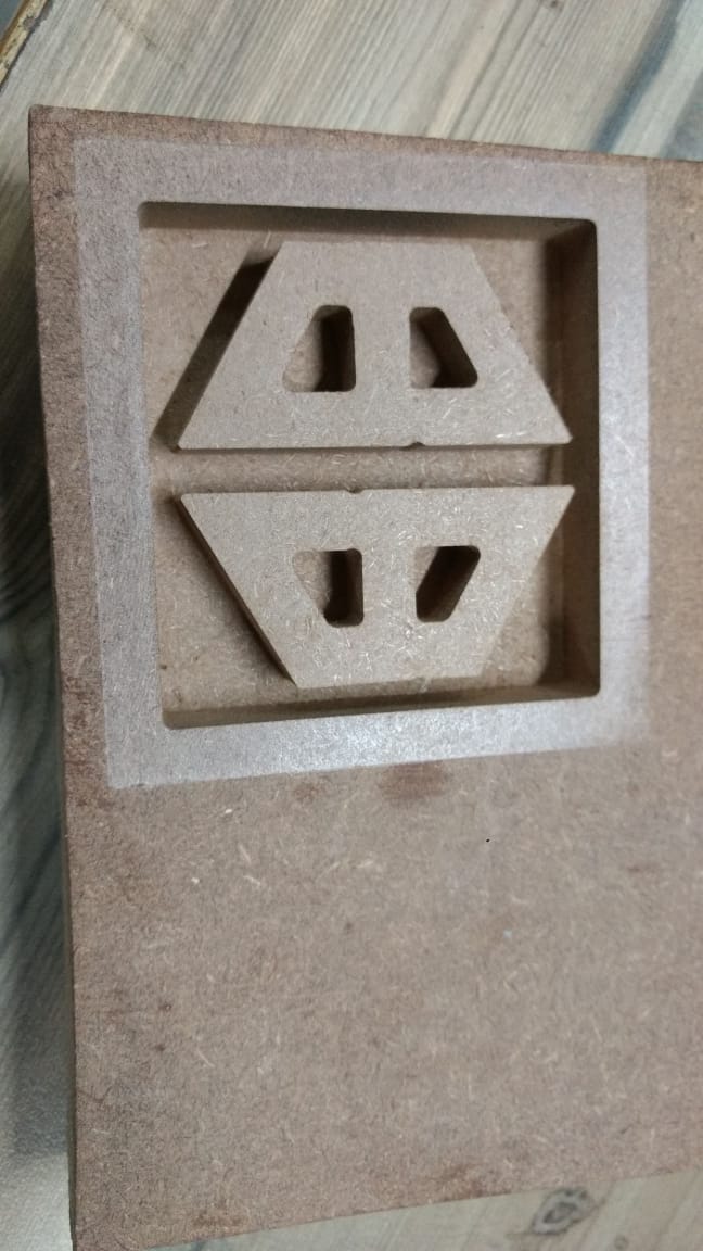
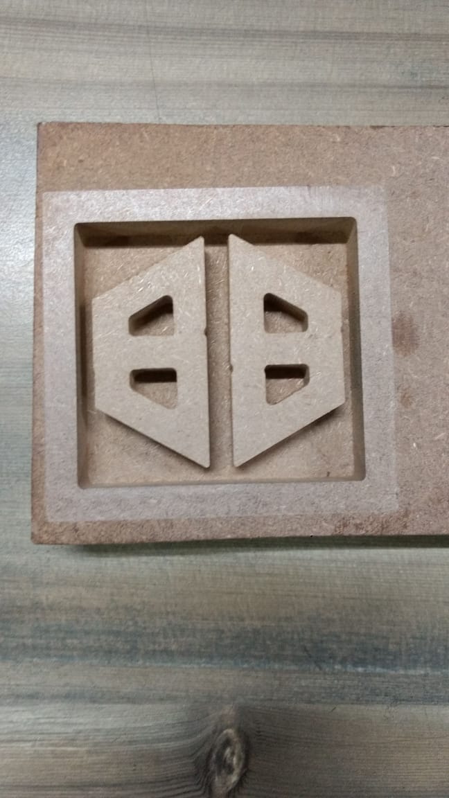
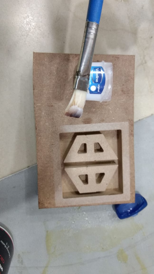
The Final Product will look like as follows :
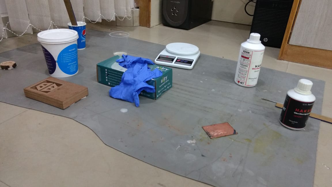
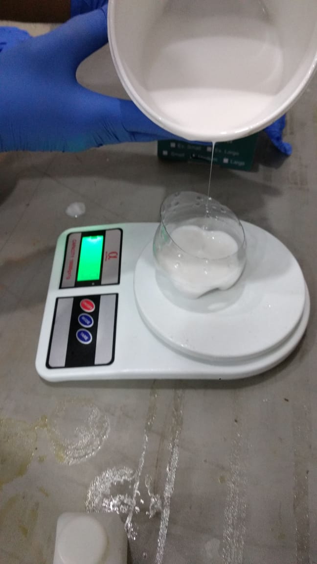
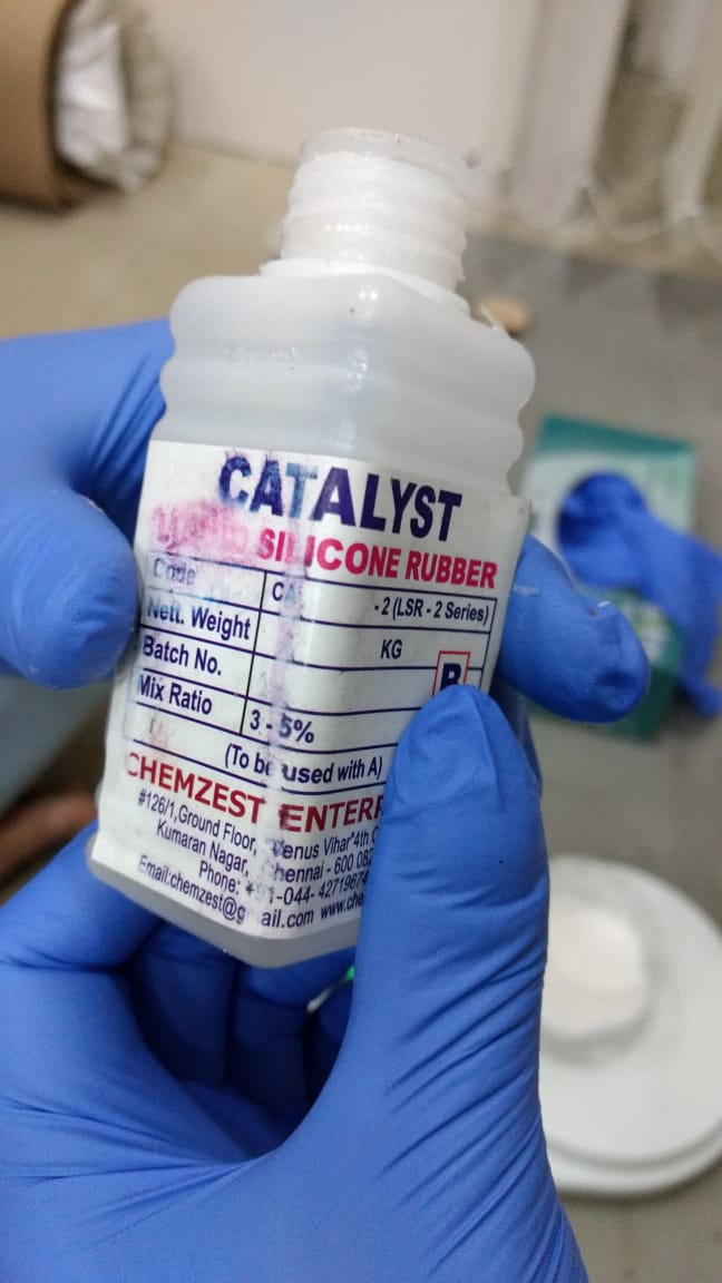
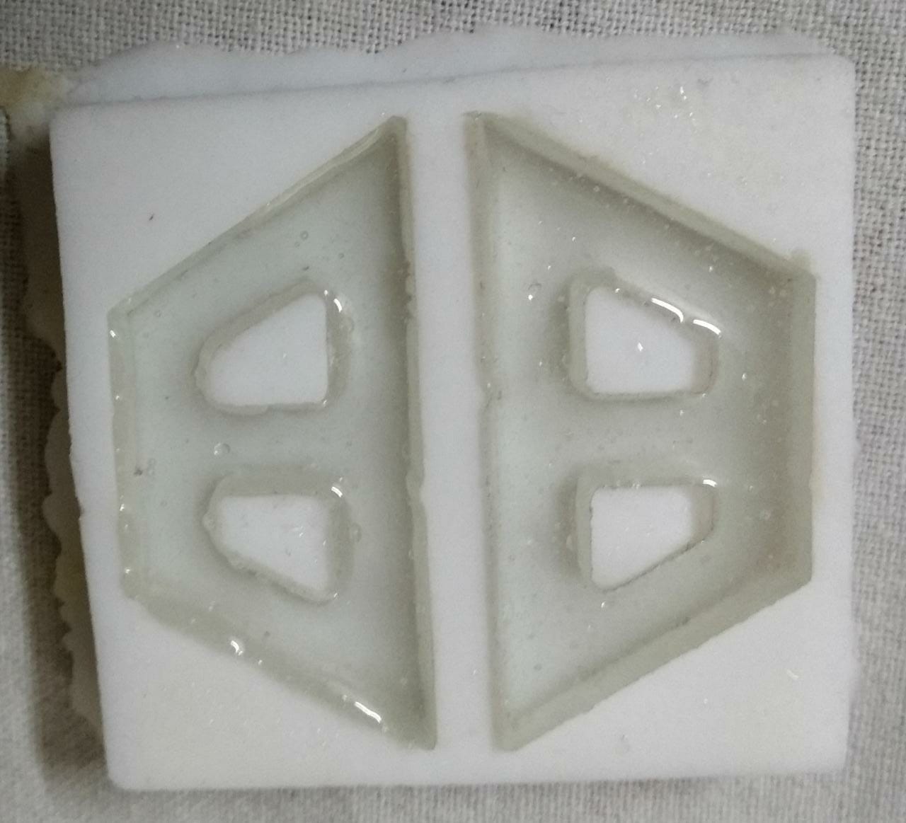
Its time to bring material for the silicon mold
Learnings:
I learned how to design molds in fusion 360.
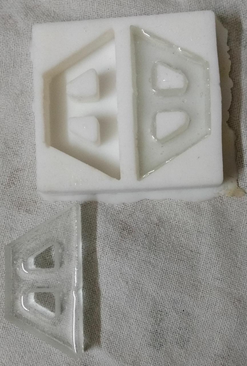
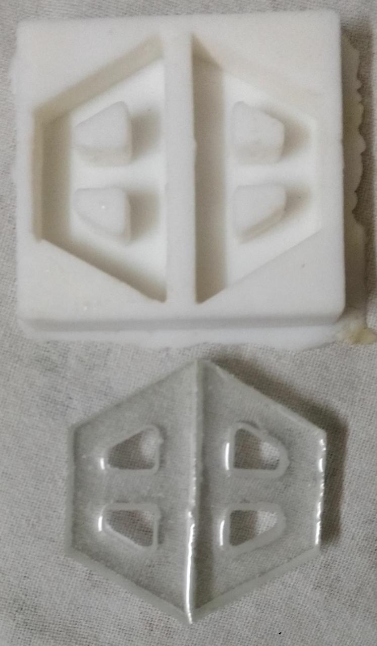
I learned that the tool size was 4mm but what i sketched for the ‘SS’ symbols i didnt provided less than 4mm for the cuts to take place. So, it came out to be ‘BB”. Still i liked it
I got to learn about various molding and casting techniques.
We come to know how SRM can be used for creating mold and not just PCB design. So explored one more feature for SRM machine
Lot of chemicals are used in molding, so its important that we use it after reading proper instructions and manual for our safety and also it made me curious how we can do this process without use of harmful chemicals.