8. Computer controlled machining
Assignment : To Make Something Big
CNC ?
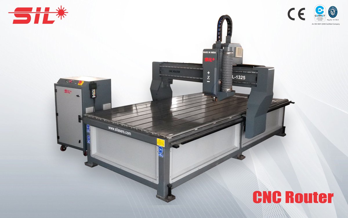
CNC (Computer Numerical Control) Machining is a process used in the manufacturing sector that involves the use of computers to control machine tools. Some of the tools that can be controlled with CNC are lathes, mills, routers, and grinders.
This technique is typically used in industries that are involved in the manufacturing of metal and plastic parts. A CNC machine is used for producing complex shapes, especially 3-D shapes that require a high level of precision which cannot be achieved otherwise through manual machining. In addition, this process is great for repetitive tasks where a specific task has to be done in exactly the same manner over and over again.
As per Fab Academy Basic guide click here to know more about CNC and relevant information.
How does it works ?
in general is a way to transform a stock piece of material such as a block of plastic and arrive at a finished product (typically a prototype part) by means of a controlled material removal process. Similar to the other prototype development technology, FDM (3D printing), CNC relies on digital instructions from a Computer Aided Manufacturing (CAM) or Computer Aided Design (CAD) file like Fusion 360, Solidworks 3D, etc.
The CNC machine interprets the design as instructions for cutting prototype parts. The ability to program computer devices to control machine tools rapidly advances shop productivity by automating the highly technical and labor intensive processes. Automated cuts improve both the speed and the accuracy with which prototype parts can be created - especially when the material is critical.
OR IN OTHER WORDS
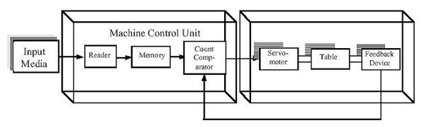
The CNC machine comprises of the computer in which the program is fed for cutting of the metal of the job as per the requirements. All the cutting processes that are to be carried out and all the final dimensions are fed into the computer via the program. The computer thus knows what exactly is to be done and carries out all the cutting processes. CNC machine works like the Robot, which has to be fed with the program and it follows all your instructions.
Some of the common machine tools that can run on the CNC are: Lathe, Milling machines, Drilling Machine etc. The main purpose of these machines is to remove some of the metal so as to give it proper shape such as round, rectangular, etc. In the traditional methods these machines are operated by the operators who are experts in the operation of these machines. Most of the jobs need to be machined accurately, and the operator should be expert enough to make the precision jobs. In the CNC machines the role of the operators is minimized. The operator has to merely feed the program of instructions in the computer, load the required tools in the machine, and rest of the work is done by the computer automatically. The computer directs the machine tool to perform various machining operations as per the program of instructions fed by the operator.
You don’t have to worry about the accuracy of the job; all the CNC machines are designed to meet very close accuracies. In fact, these days for most of the precision jobs CNC machine is compulsory. When your job is finished, you don’t even have to remove it, the machine does that for you and it picks up the next job on its own. This way your machine can keep on doing the fabrication works all the 24 hours of the day without the need of much monitoring, of course you will have to feed it with the program initially and supply the required raw material.
Most of the manufacturing companies are now equipped with the CNC machines as the markets have got very competitive; however, getting the expert labors for operating these machines is becoming quite difficult. Even the machine operators of these days prefer to operate the machine by programming instead of operating it manually. In most of the machine tools training institutes the new operators are taught manual machining as well as CNC machining and programming.
## Material
Almost any material can be used in a CNC machine. It really depends on the application. Common materials include metals such as aluminum, brass, copper, steel, and titanium, as well as wood, foam, fiberglass, and plastics such as polypropylene.
Useful links (info)
Designing
I thought to design using a tutorial of LAPTOP STAND in Fusion 360 form here
Lets start making the New Component for the LEGS of laptop stand by rught clicking the top of the browser and name it LEG.
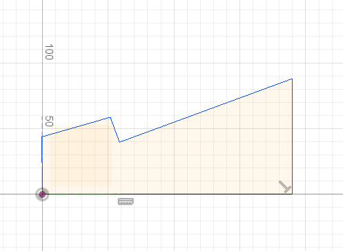
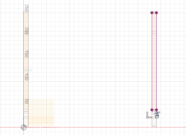
Now lets sketch for the side profile of the legs by turning on the origin bulb will help keep things aligned. From the origin draw a horizontal constraint. Move a perpendicular line up n make an angle from there around 160(tentative) and then make a perpendicular from there and align the first point from there with the line and finish it off by going to the point down of the origin.
Looks something this :
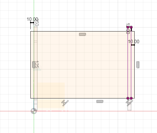
Now i can apply any additional constraints that i need to eliminate degrees pf freedomm in my sketch. And then add dimensions to lock it.

One constraint to apply as a parallel constraint between above marked lines. For that choose parallel for my sketch palette choose them and becomes parallel.
Now, From the sketch drop down menu choose sketch dimension and put values for the first line drawn from the origin to the right of it be 225mm.
From there the perpendicular drawn earlier working as height be 125.
The line Opposite to 125mm height line shouldd be 55mm. You get this figure
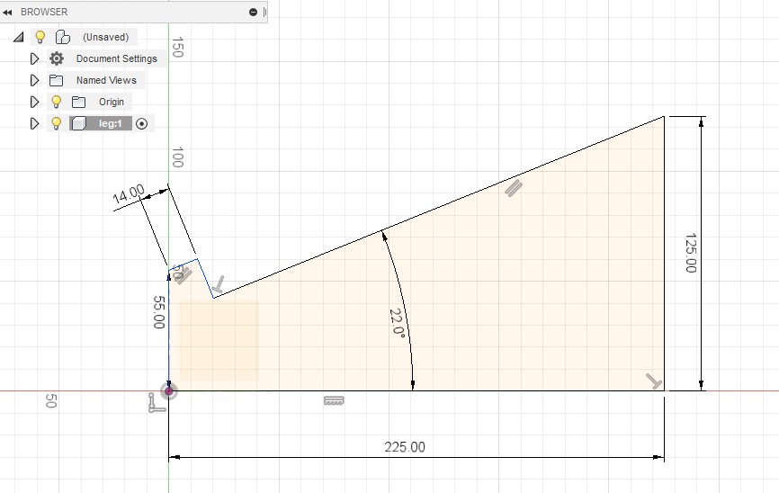
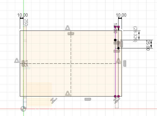
Now stop the sketch to see the sketch profile, before thet set the users parameters as it is fully parametrics. From the Modify menu choose the option change parameter and set the following paramters
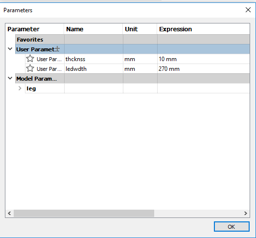
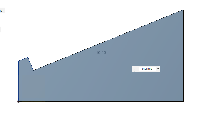
We can now use the parameters for all the features from now on. From the create menu choose excrude or simply press E. Select the sketch profile for the thickness for extrusion and type ‘thcknss’ to extrude it 10mm.
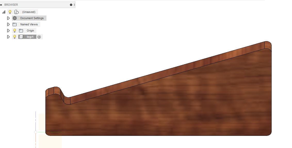
Now you can put Fillets on the edges of the designs you can find the fillets command in the modify drop down menu. In the image its extrude and fillets done.
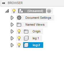
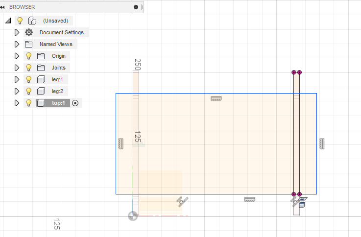
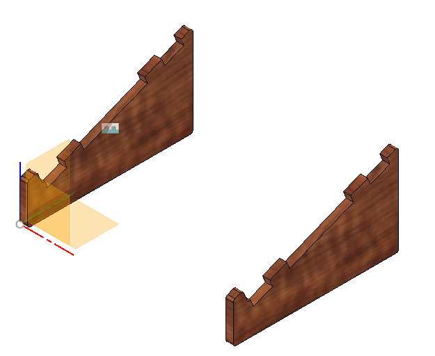
We have just made one leg of the laptop stand but we want two stands for the same. So, we will activate the top level of the design and copy and paste of the sketched leg.
By coping the legs if we change dimensions in any leg it will also reflect in the other one as they are copied. you can see Leg1 and Leg2
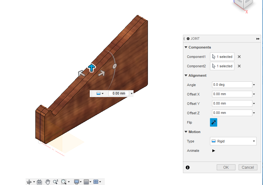
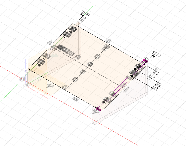
we will now set the leg width of the stand by using the joint option from the Assemble drop down menu.
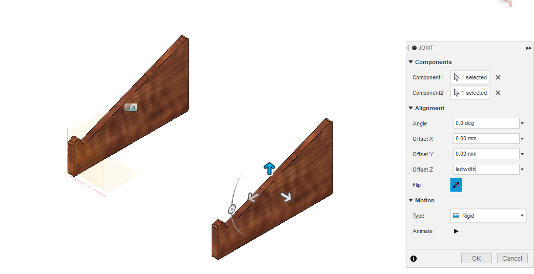
And add offset instead of zero in the Z axis, type ‘ledwdth’ and press okay . ou will get this.
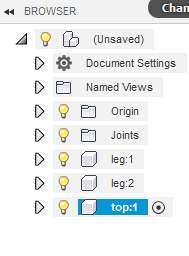
We will create New component for the Top of the stand and start sketching on the slant top of the stands.

Make another geometry from the sketch drop down menu choose project>include or use the hot key “P” and go select the slanted top of other leg and press okay
Draw 2point rough recatngle and then add some constraints, align the existing edges and plates.
Mirror the dimensions set with the help of mirror lines
After mirroring the lines it will look like this
Hit Stop sketch and start to extrude the mentioned profiles

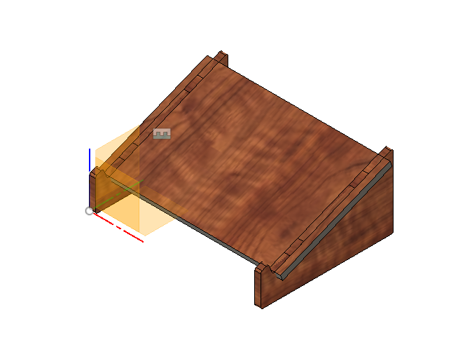
Use the combine option to remove material from the leg for that choose the leg as target body and tool body as the top. Make sure to use the CUT option not the join one.

You can add more fillets to the edges for the smooth edges.
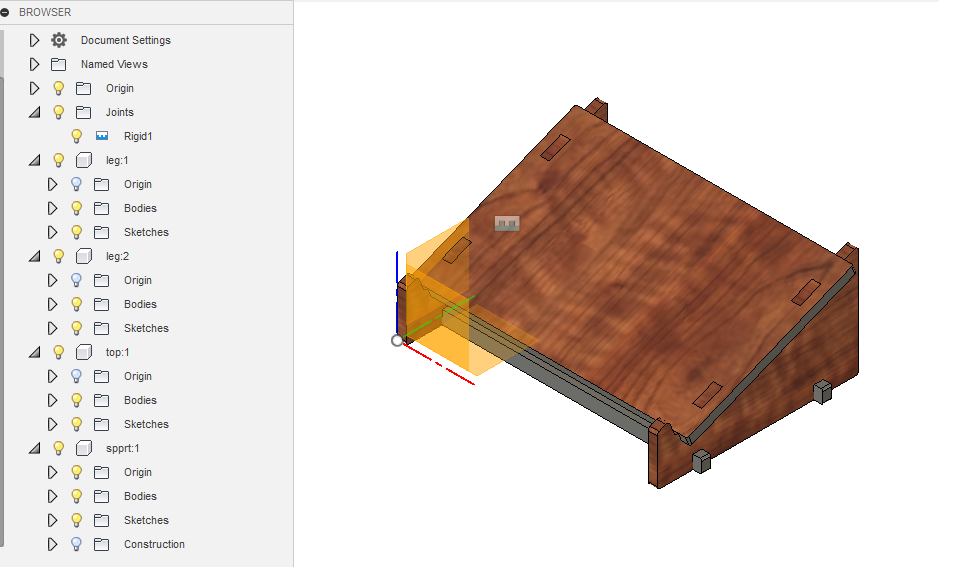
Learnings:
Its amazing what we can build on CNC machine
I was successfully able to use the CNC machine and cut the part
Safety is very important to operate the machine
We can even learn by sound of machine whether its working fine like Spindle speed you can just see if its cutting properly or machine is taking a load