5. Electronics production
This week I worked on group assignment: characterize the design rules for your PCB production process individual assignment: make an in-circuit programmer by milling the PCB and soldering it with components.
Started
PCB Milling Roland SRM 20 is the machine we used for this assignment. As a small milling machine, the SRM-20 offers compact size and powerful functionality at an affordable price. Production of realistic parts and prototypes is made simple and convenient with a device that fits into any office, studio, or classroom environment. For users looking for advanced milling capabilities without the need for expert operating skills, the SRM-20 is one of the easiest and most precise CNC mills in its class. MonoFab SRM-20 Specifications

Software used SRM 20 [V-Panel] here
Step 1 obtain the Test files
We simply downloaded the PNG file from the Fabacademy Schedule page then using Fabmodules we made .RML file

# Step 2 Modules
We opened the FabModules Page. And in the input format, selected ‘image.png’ option for the traces image. Then, output format - roland mill (.rml) and process - PCB traces (1/64) we always use the same x0,y0,zO that you used for the trace files or both cuts will not match. select the machine as mine was roland SRM 20 and click calculate
Output

Building the FabTinyISP
FabTinyISP: This version (the “FabTinyISP Minimal” is a minor revision to Zaerc’s version 0.3 (Bas), with small modifications:
The reset switch and target power switch have been removed. The reset switch adds cost and isn’t incredibly useful on an ISP programmer, as the target can be easily reset through a software command. The target power swtich has been removed as providing power to the target through the programming port is usually discouraged. Users who understand the implications of this are welcome to build one of the FTS designs with the switch. The copper ground pour has been removed and replaced with individual ground traces; this allows novice solderers to mill away more of the copper. All components solder to clearly defined pads on both sides. The extra pads connecting to the USB data lines were removed; this version is targeted solely at being an ISP programmer rather than being a general-purpose tiny45 board.
The PTC thermistor was removed; as this part currently isn’t in the inventory most users would build it with a 0Ω resistor anyway. As the option to provide target power has been removed, it should be much more difficult to create a condition where the polyfuse would be needed. The Makefile has been replaced. Targets for programming the fuses on an ATtiny45 have been added. The original Makefile also results in problems on case-insensitive filesystems (i.e. Windows). This page describes how to build, program, test, and debug the board.
Issues
We don’t had material available in lab for vinyl cutter to create PCB circuits.
We were not having the proper soldering wire, double sided tape and hex key available in lab
Worst of all the milling machine sacrificial layer and bed was not leveled resulting in non creation of proper traces and we spent most of our time debugging and fixing the machine rather than focussing on the week’s assignment.
PCB

open and process the above image in Fabmodules


open the fts_mini_cut for cutting the outlines.


Open the VPanel for milling the prepared files. Click on “cut” to select the downloaded rml file and then click on “output” to start milling. Now, mill the PCB.

Download the PNG files for the traces and the board outline here and here
After downloading the traces and the outlines for the PCB fabrication. We again used FABMODULES to calculate and save the .rml files

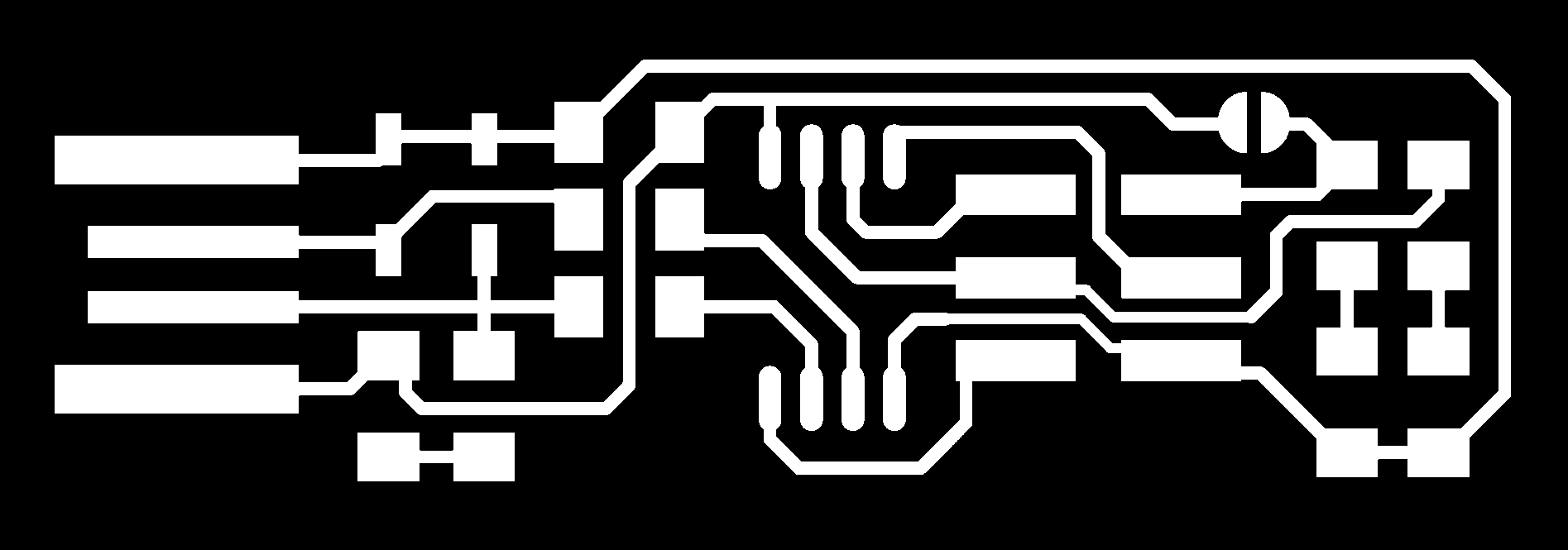
The output of file looked like this :


Assembling the PCB
The obtained components are :
1x ATtiny45 or ATtiny85
2x 1kΩ resistors
2x 499Ω resistors
2x 49Ω resistors
2x 3.3v zener diodes
1x red LED
1x green LED
1x 100nF capacitor
1x 2x3 pin header

Soldering the components
First Component


Few more


Final Output

Programming FabISP
For programming the FabISP I followed the instructions given on Brian’s page
Steps:
First, download the Atmel AVR toolchain and extract the files in c:\program files.
Download GNU Make and install in c:\program files(86) directory.
Install avrdude.
Then, update the path to tell the windows where to locate the tools you’ve just installed. Follow instructions on Brian’s page.
Download Zadig to install the drivers.
Connect the FabISP, select AVRISP mkII as the programmer and install libusb-win32 driver.

Use below commands for Sanity check


Next step is to download the firmware file. Unzip and extract the files. Open your terminal program and navigate to the directory(firmware) and run make command. It will generate a hex file (firmware_fts.hex).

Open the hex file and change the name of the programmer from usbtiny to avrispmkii


Connect the board to the USB jack and programmer to the ISP header of the board. Make sure the orientation is right(MISO –> MISO). Run make flash. This will erase the target chip, and program its flash memory with the contents of the .hex file you built before. Run the make fuses command. This will set up all of the fuses except the one that disables the reset pin. Run make rstdisbl. This does the same thing as the make fuses command, but this time it’s going to include that reset disable bit as well.

Learnings
I successfully milled the PCB using monoFab milling. Got to know about FabISP. Successfully programmed the FabISP to make it program other boards