This week, I took a look at input devices, i.e. sensors which enables my boards to detect properties of their environment. Together with the next week, I'm able to construct devices that can act on, observe, and react to their surroundings. That's very exciting, because it enables so much possibilities!
Temperature sensing coaster
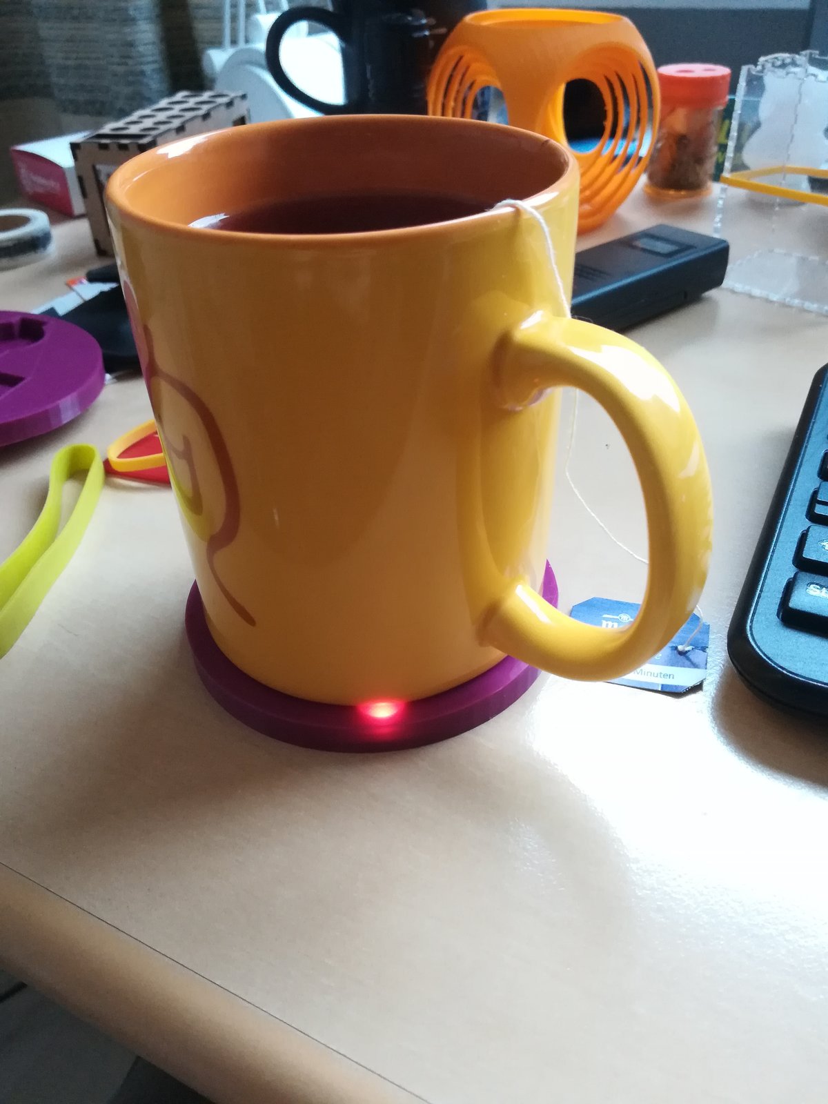
As a first, rather simple excurse into sensors and transducers, I used a temperature dependent resistor and a LED to make a coaster for my tea mug that shows me if my tea is safe to drink, too hot, or undrinkable cold. I wanted to make the coaster as practicable as possible, so my goals are:
- Simple to use - ideally without user intervention. Just put your cup on the coaster, and it will light up.
- It should not be thicker than ~1cm, otherwise it feels and looks too clunky.
- I want it to be powered with a single coin cell (i.e. at 3.3V), and I don't want to change the battery every few days, so it should consume as little power as possible.
I achieved a working solution, but that's only because the blue LED works with a lower voltage than indicated in the data sheet. However, it should be possible to incorporate an inductor to construct a simple flyback converter which could power the LED regardless of the input voltage. I will explore this possibility in the next week.
I used the following materials to make my coaster:
- The case is made out of 3D printed PLA (around 30g)
- Attiny45
- RGB LED (three LEDs in one package)
- 680Ω resistor for the red LED
- 560Ω resistor for the green LED
- 470Ω resistor for the blue LED
- 10kΩ pull up resistor
- 24kΩ balance resistor
- 4.7kΩ NTC thermistor
- 100nF capacitor
- 2x3 SMD pin header
- PCB mill
- 3D printer
- Laser cutter
- Soldering paste + hot air gun
Version 1
The first version I made used a very small PCB that would be pushed into the coaster; due to the low height and small outline of the PCB, it was necessary to program the chip and then remove the ISP header, otherwise the board would not fit in the coaster. This proved to be quite error prone, as I bricked several ATTinies trying to get this to work. Nevertheless, I had a prototype. I later designed Version 2, which features a larger board, easier assembly, and which could be reprogrammed easily. What's more - and maybe most important - Version 2 has a battery slot, which I forgot to add in the first try. Additionally, I derived the necessary calculations more thoroughly, using only integer values.
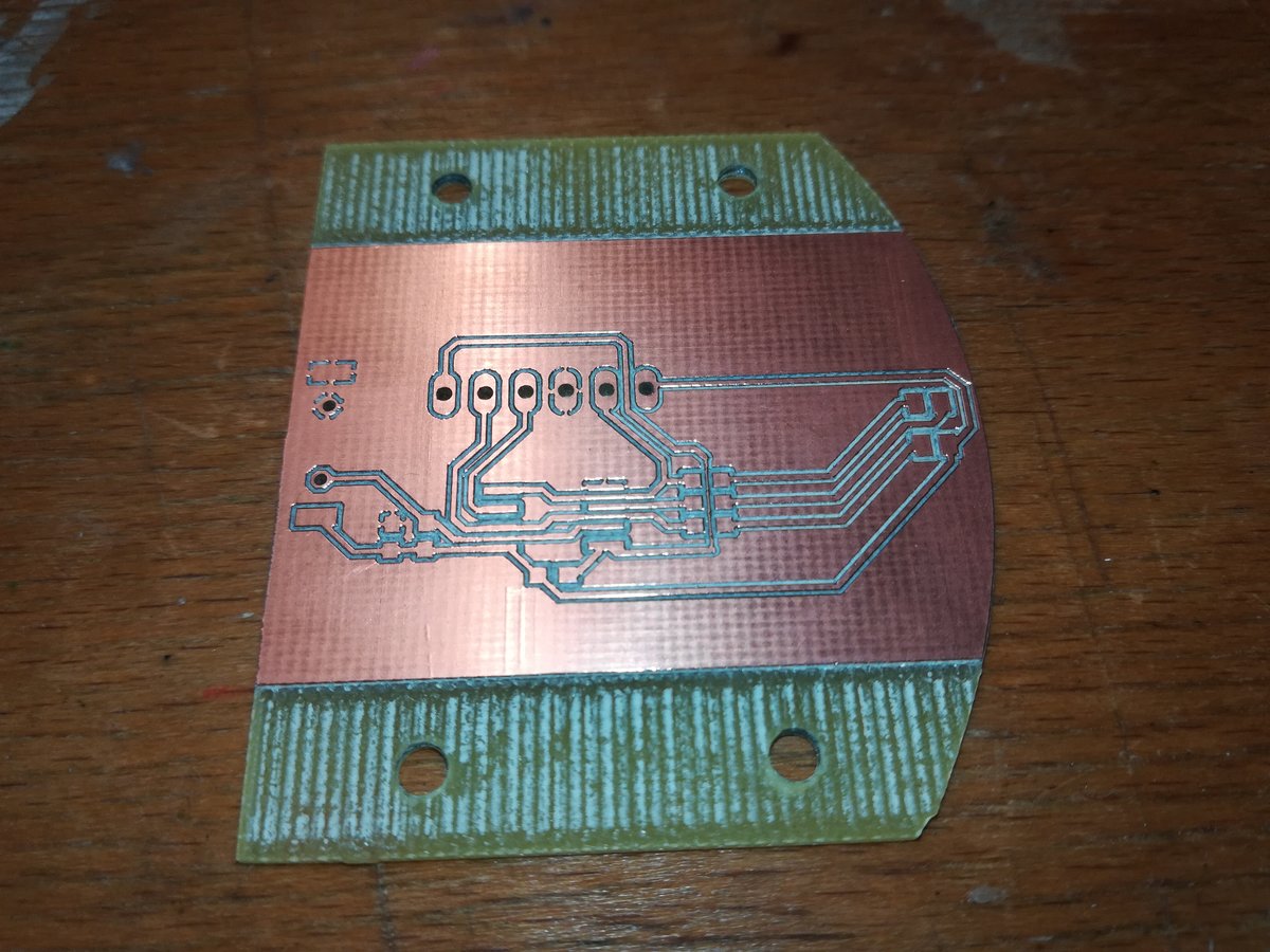
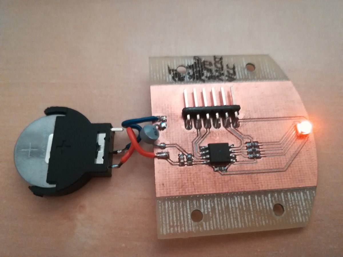
The board
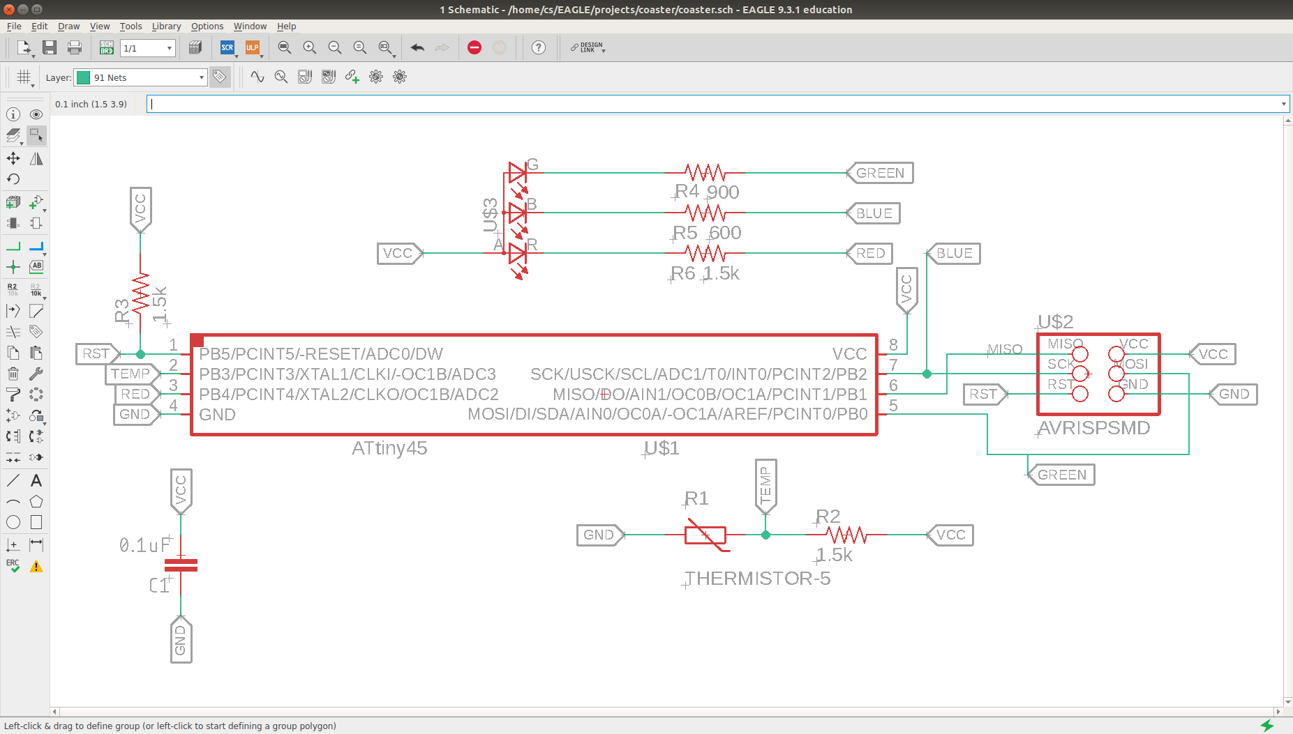
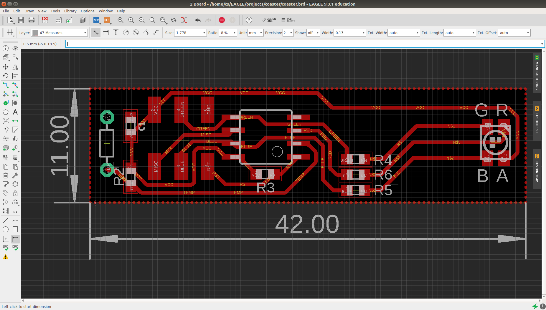
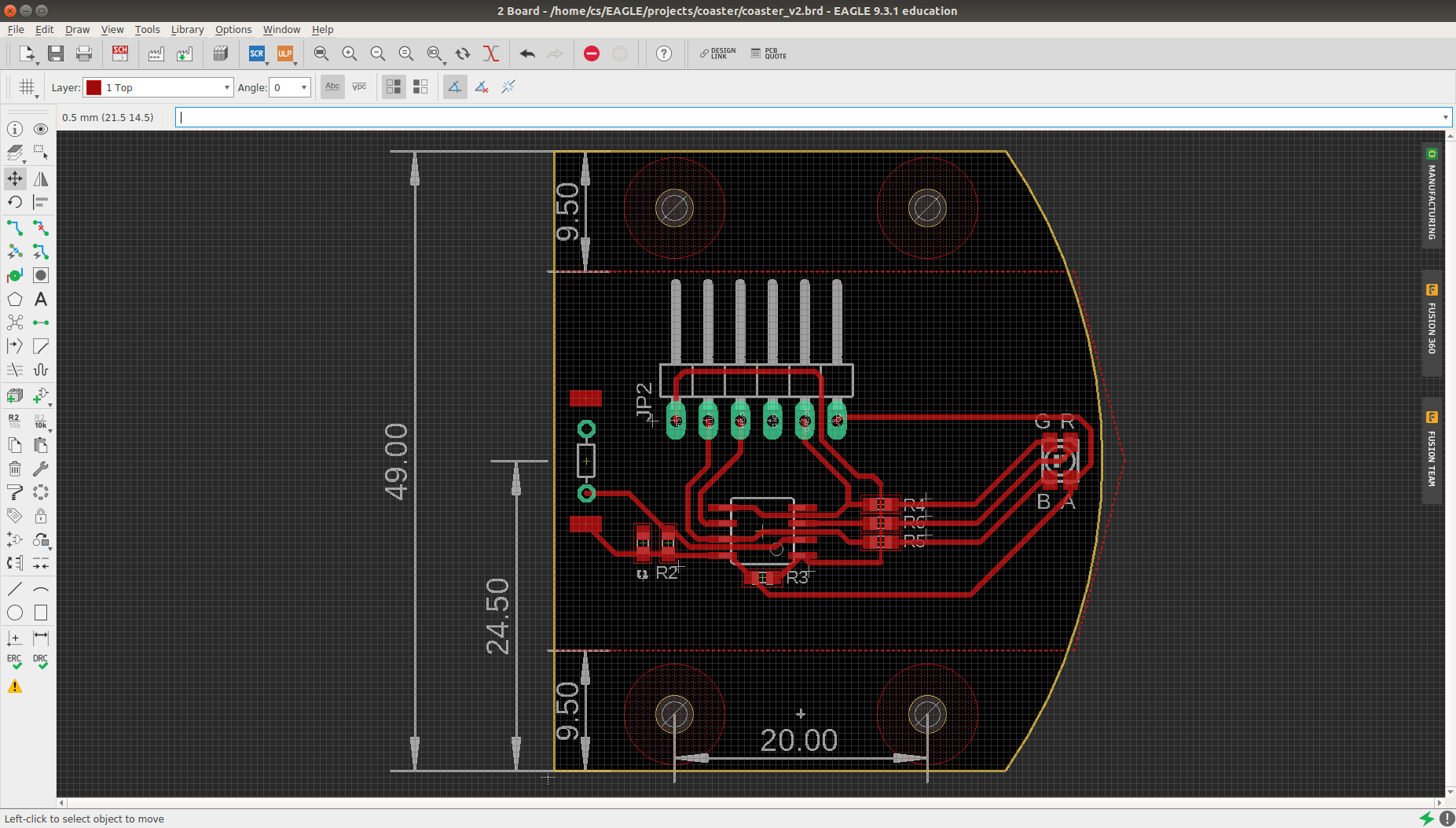
Since the Attiny45 only has 6 I/O pins, I had to assign multiple functions to some of them; most notably, the signal pins to program the Attiny are the same pins that control the LEDs. I used the 24kΩ resistor and the thermistor to create a voltage divider, which is connected to pin 3 of the analog to digital converter (ADC) of the Attiny. The schematic and the routing below were done in Autodesk Eagle. They can also be found in the download section.
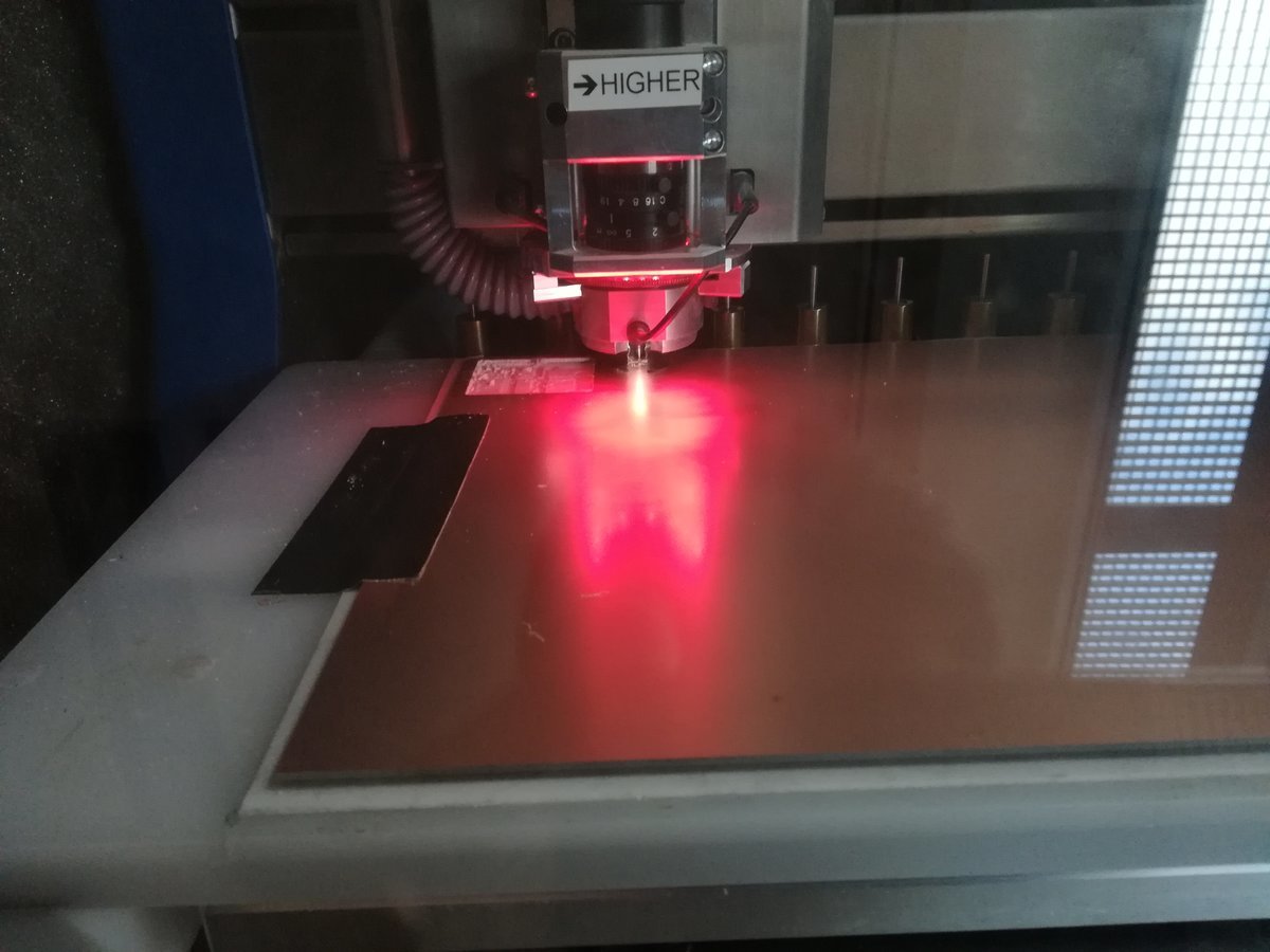
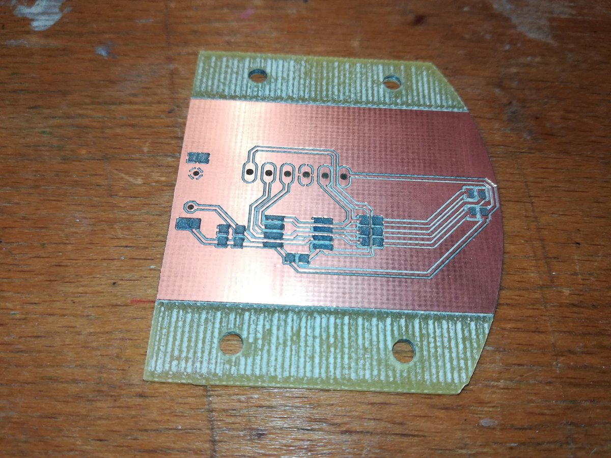
I milled the board in our PCB mill and made a stencil out of plain 80g/m^2 with our laser cutter. The stencil can be exported from Eagle with a ULP (user language program) (eagle2svg-1.3.ulp on the Autodesk download page; just select the layer "tCream" and run the ULP). In VisiCut, the settings for paper work very well to create stencils, but for very small footprints it might be beneficial to scale the individual pads down in Inkscape to account for the laser cutter kerf. After the board is stuffed, I use a hot air gun to evenly heat the board and solder all the components. When working with small components (i.e. 0603 or 0402) make sure to slightly press them into the solder paste, otherwise they might lose contact on one side if the board isn't heated up evenly enough.
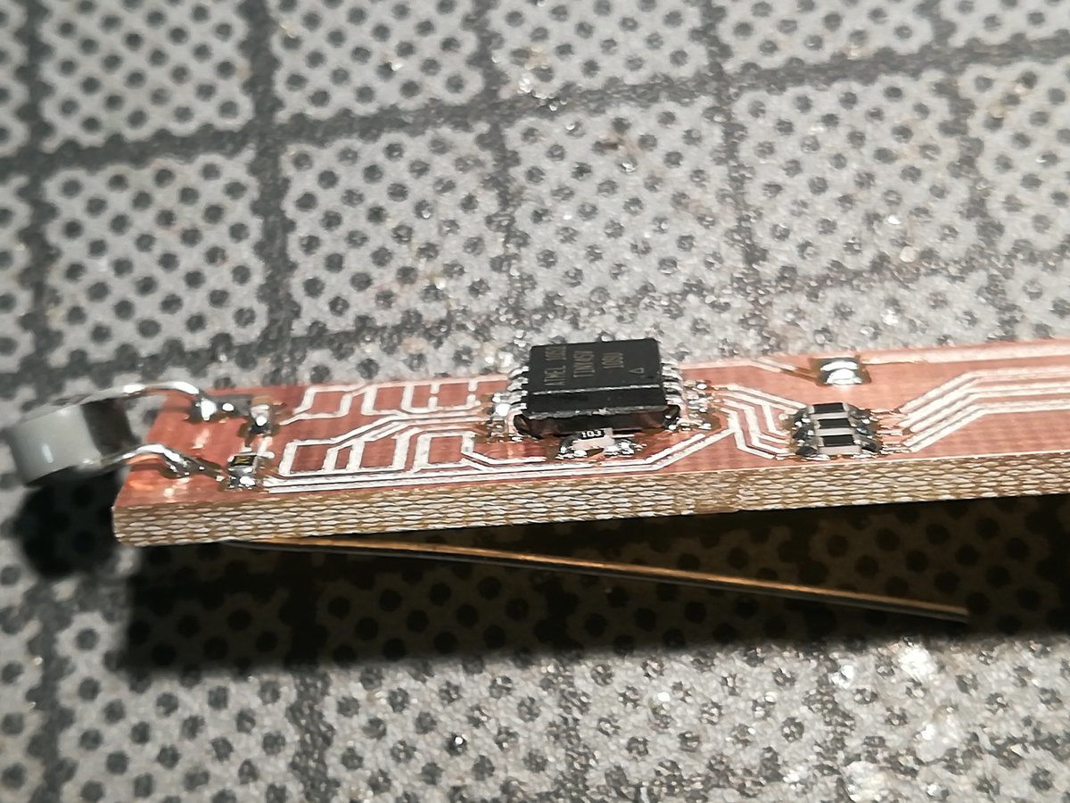
Making the board this way took me only around 45 minutes, but when I wanted to program it, I messed up some wires... and apparently neither the Attiny nor the LED took that well, as the board began to smoke after a couple of seconds. Luckily, neither my Laptop nor my ISP took damage, but the board was completely bricked.
So I made another one. This time, clever me decided it would be nice to try not to solder the ISP header onto the board, but just program it while holding the contacts together. Needless to say, it didn't go too well and I had another short. Well, third time's the charm, right?
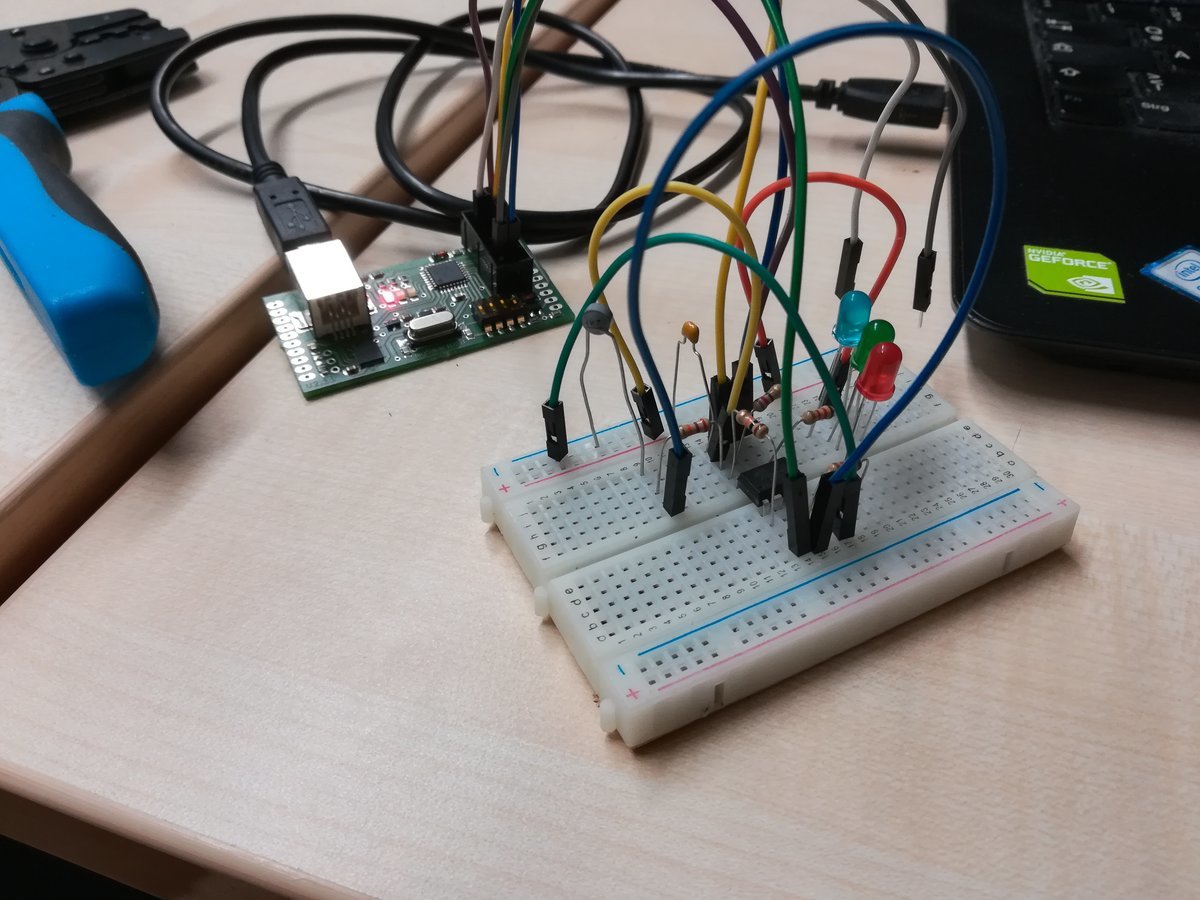
By this time, I'm not sure if my circuit is working as I think it is. So instead of making a third board (and possibly bricking it again), I set up a breadboard and started programming the Attiny. This way, I could start small (i.e. only one LED; three LEDs; three LEDs and thermistor) and check if everything worked out as I thought it would. It did. Hurray! But it took me quite some time to connect all the cables correctly, and it was definitely messier than a PCB.
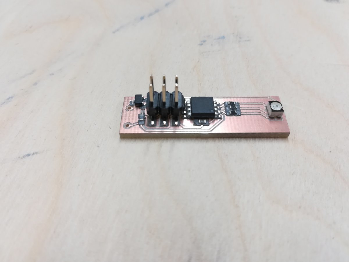
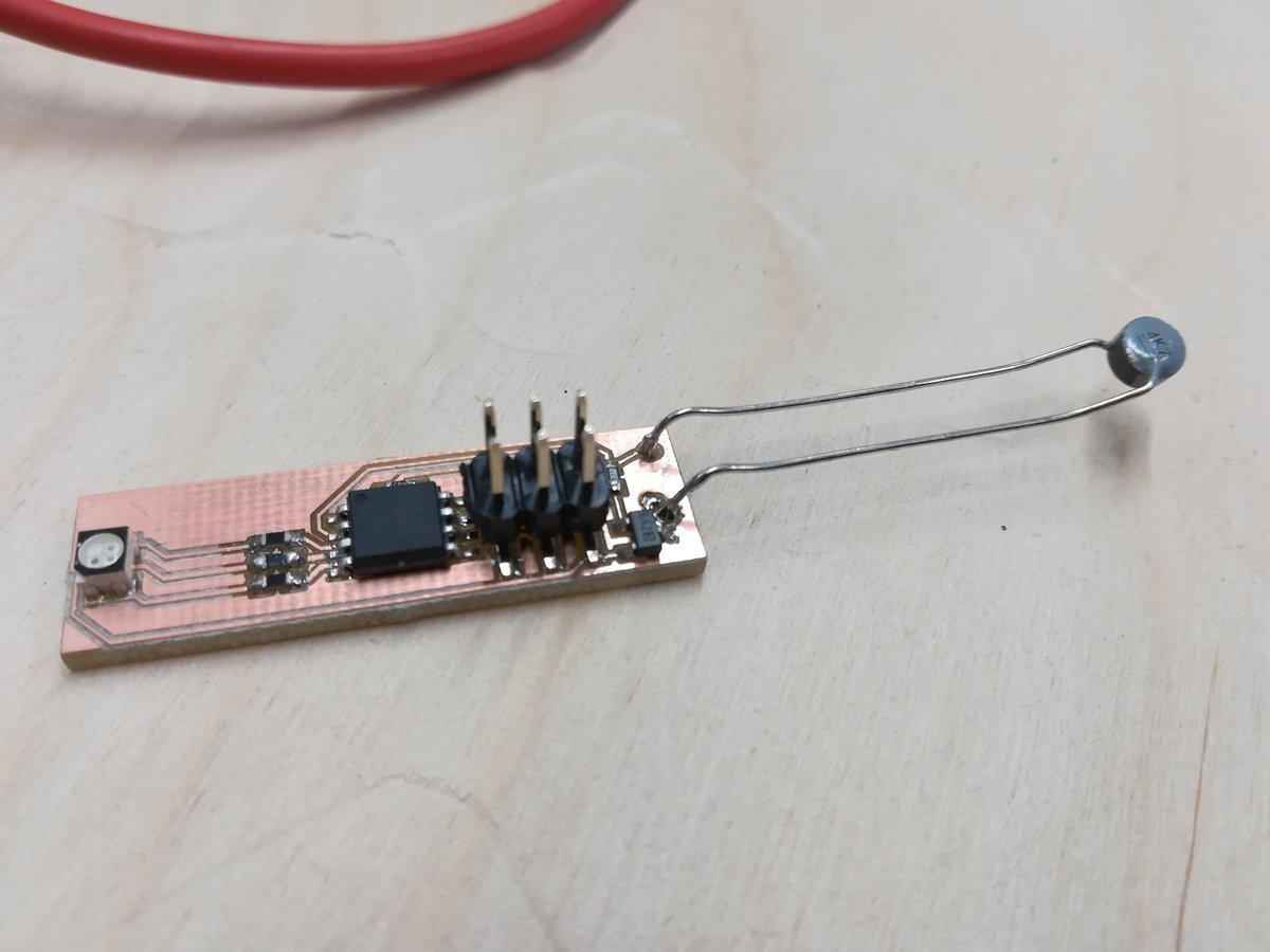
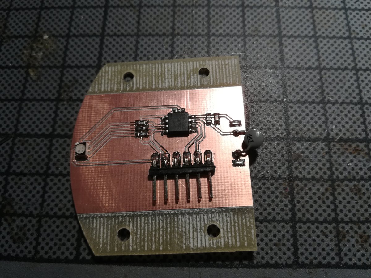
So I set out to make the third board, and this time it actually worked.
After programming, I have to remove the ISP header with a hot air gun so the board fits into the coaster.
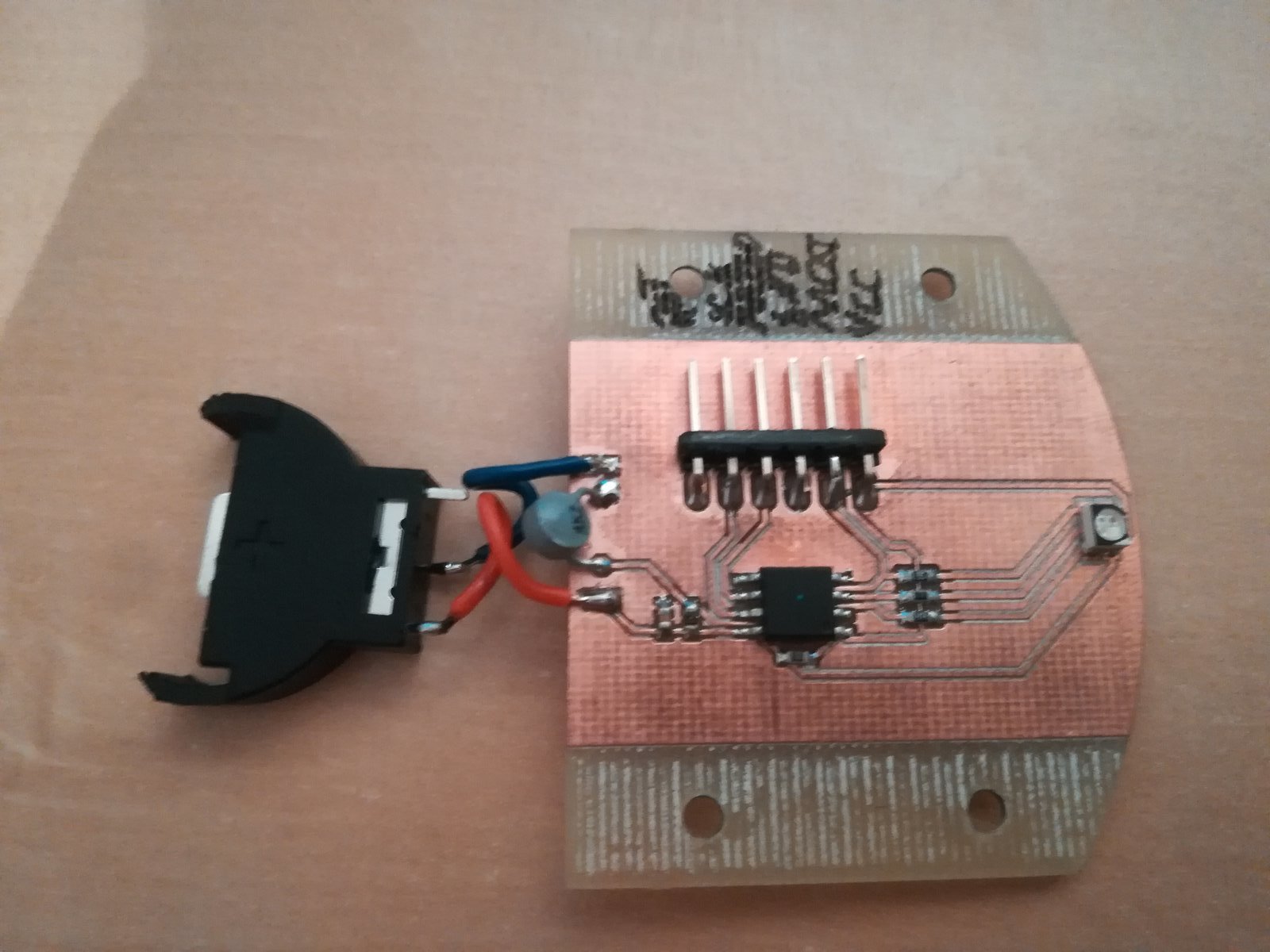
I also noticed that I don't have a way to connect the coin cell.
Well, it's good enough for prototyping.
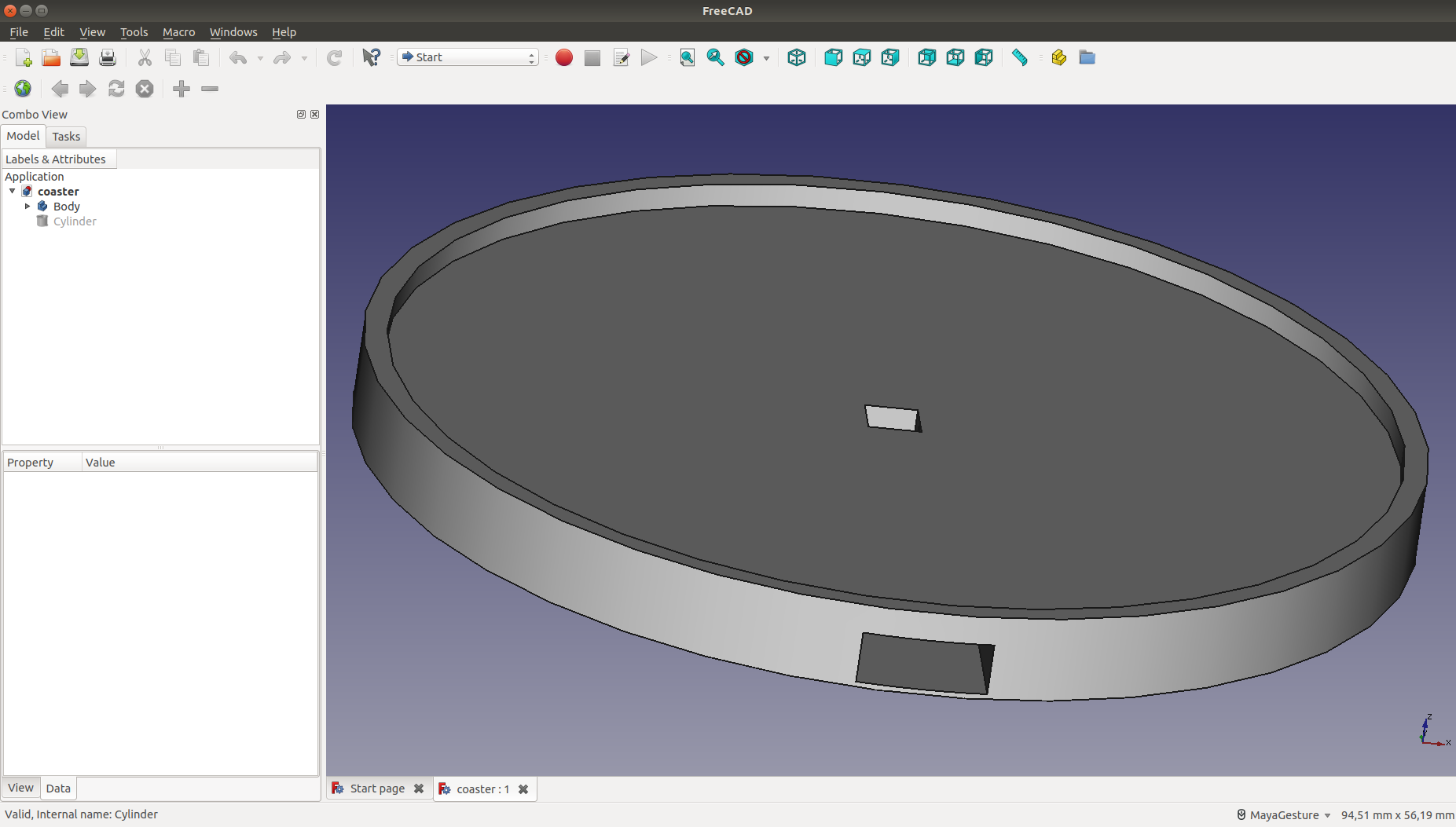
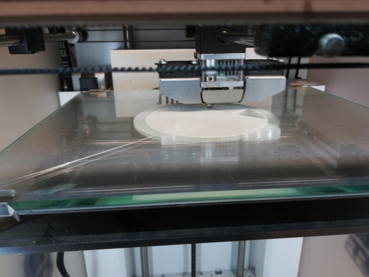
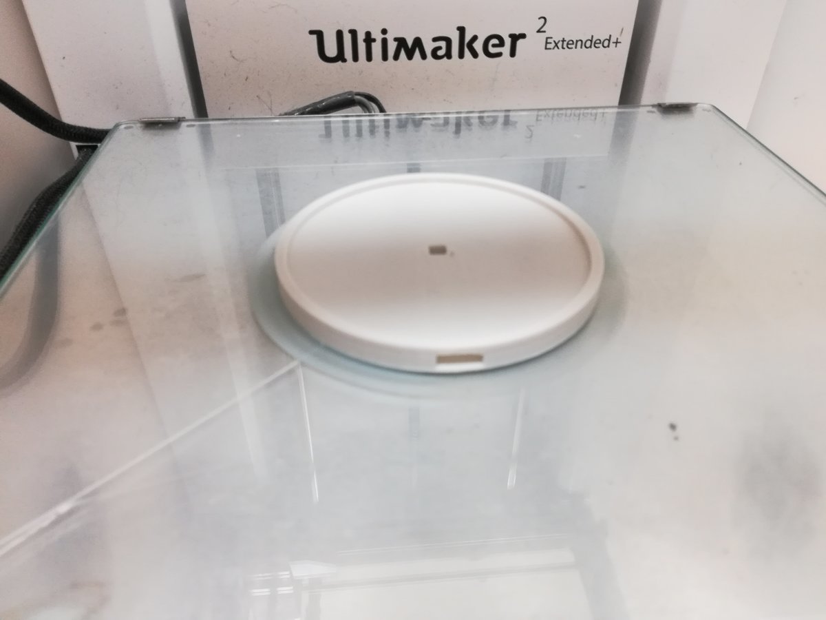
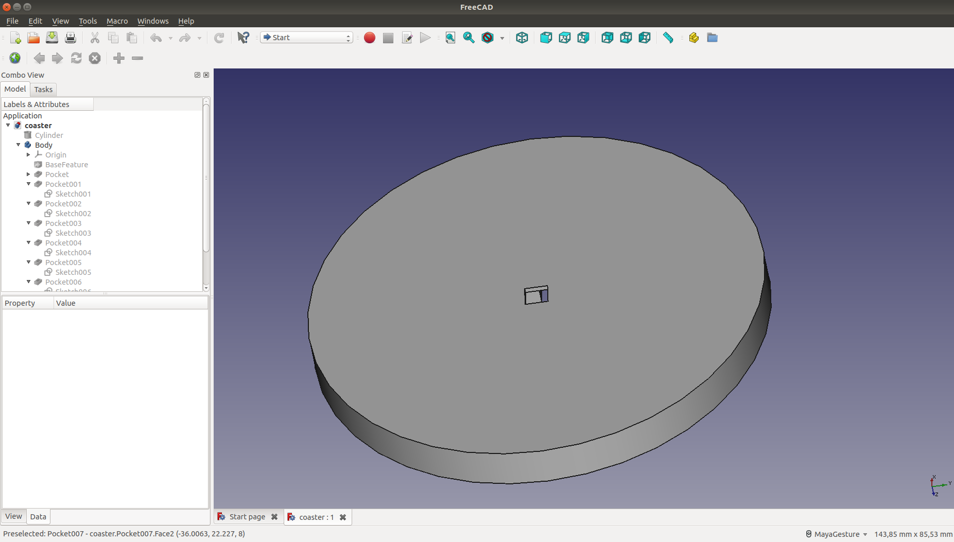
The coaster
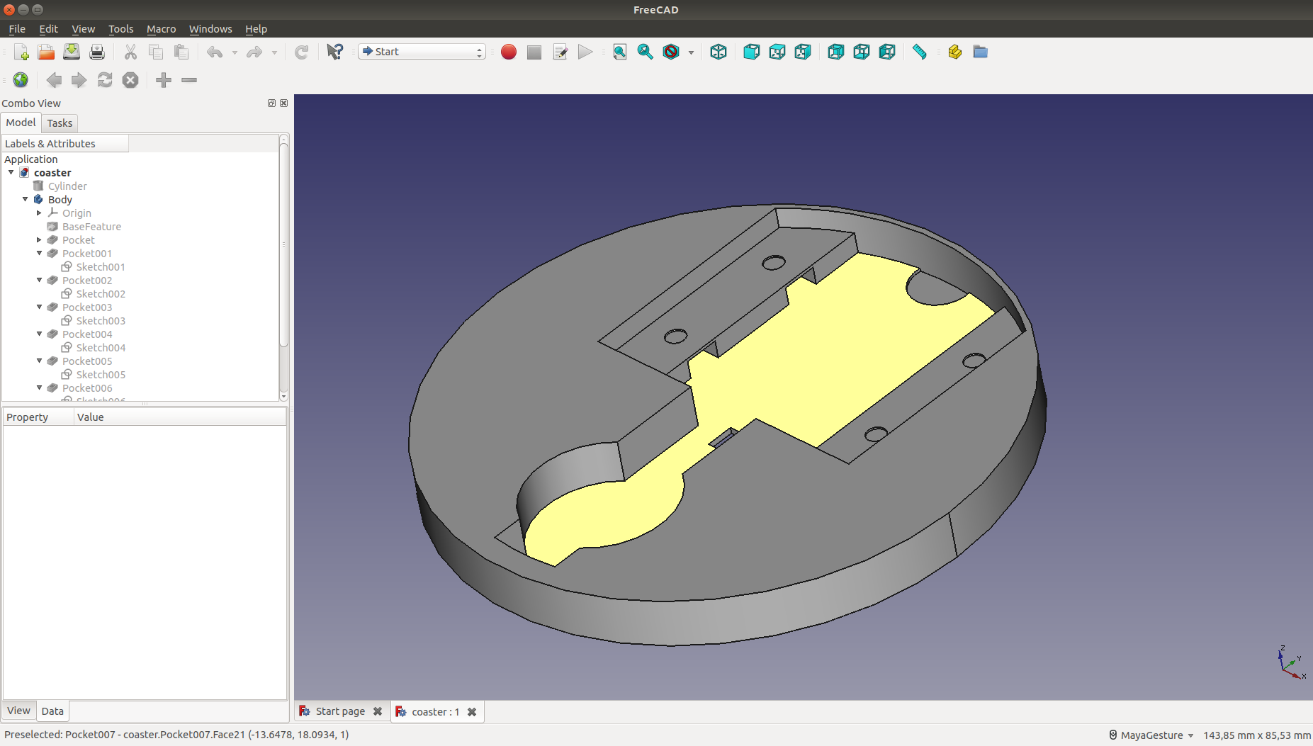
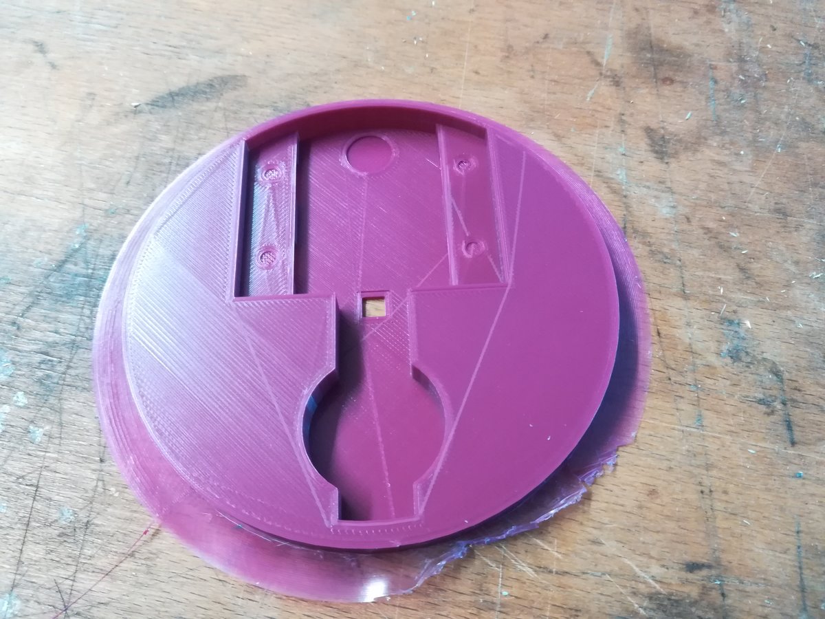
I designed the coaster in FreeCad. It's really simple, just a cylinder with a slot in one side for the PCB and a hole in the middle for the temperature sensor. Printing it on an Ultimaker 2 Extended+ took a little more than 2 hours. I was actually surprised how well it turned out, since the upper part of the slot was printed without any support material.
The firmware
The firmware is the most complex part of the coaster. It has to periodically use the ADC to read a temperature dependent voltage, convert that to a temperature (averaging over a couple of measurements), and control the LED appropriately. When it's not actively measuring or controlling, the microcontroller should enter sleep mode. It has to detect when there is something to measure (i.e. temperature suddenly increases a couple of degrees), and when to stop measuring (room temperature is reached, no changes for some time). All of this with only 6 pins and a single sensor.
So let's start! We will use timer 0 of the Attiny to schedule ADC conversions, which trigger an interrupt when finished, which will update the LED status. At all other times, the microcontroller will be in power saving mode. First, we initialize the LED pins.
// Enable pull-up resistor after tristate (see datasheet)
LED_PORT |= (PIN_RED | PIN_GREEN | PIN_BLUE);
// configure as output
LED_DIR |= (PIN_RED | PIN_GREEN | PIN_BLUE);

// turn LEDs off
LED_PORT |= (PIN_RED | PIN_GREEN | PIN_BLUE);
Then, we initialize the ADC to compare a positive voltage on ADC3 to the internal 1.1V reference. Comparing to the internal reference has the advantage that it is stabilized even when the battery voltage drops, without the need of an external voltage regulator.
// Select single ended input on ADC3
ADMUX |= (1 << REFS1) | (1 << MUX1) | (1 << MUX0);
// Enable ADC, ADC auto triggering, and ADC interrupts
ADCSRA |= (1 << ADEN) | (1 << ADATE) | (1 << ADIE);
// Configure ADC to trigger on overflow of timer0
ADCSRB |= (1 << ADTS2);
After that, we initialize the timer and enable overflow interrupts.
// Halt timer for configuration
GTCCR |= (1 << TSM);
// Enable timer0 overflow interrupt
TIMSK |= (1 << TOIE0);
// Use no prescaling on timer0
TCCR0B |= (1 << CS00);
// Start timer
GTCCR &= ~(1 << TSM);
Then, disable unneeded peripherals, enable interrupts globally and prepare to sleep.
// Disable ADC buffer on unused ADC pins
DIDR0 |= (1 << ADC0D) | (1 << ADC2D) | (1 << ADC1D);
// Disable analog comparator
ACSR |= (1 << ACD);
// Shut down timer1 and USI module
PRR |= (1 << PRTIM1) | (1 << PRUSI);

// Enable interrupts
sei();

// Select ADC noise reduction sleep mode
MCUCR |= (1 << SM0);
// Enable sleep mode
MCUCR |= (1 << SE);
The ISR that is triggered when a conversion finishes only updates the global temperature variable.
uint16_t temp;

ISR(ADC_vect){
  temp = ADCL;
  temp |= (ADCH << 8);
}
Finally, the main loop: sleep until woken, update LED status, go back to sleep.
while(1){
  // sleep while waiting for ADC conversion
  sleep_mode();

  //LED_PORT |= (PIN_RED | PIN_GREEN | PIN_BLUE);
  if(temp >= 780) {
    LED_PORT &= ~(PIN_GREEN|PIN_BLUE);
  } else if(temp > 700) {
    LED_PORT &= ~(PIN_GREEN | PIN_RED);
  } else if(temp > 500) {
    LED_PORT &= ~(PIN_GREEN | PIN_RED);
  } else {
    LED_PORT &= ~PIN_RED;
  }
}
The program is compiled and uploaded with a make file, similar to that of the embedded programming week.
Redesign (aka Version 2)
For the redesign, I changed the coaster so that the PCB is inserted from the bottom and held in place with screws; also, I added space for the battery.
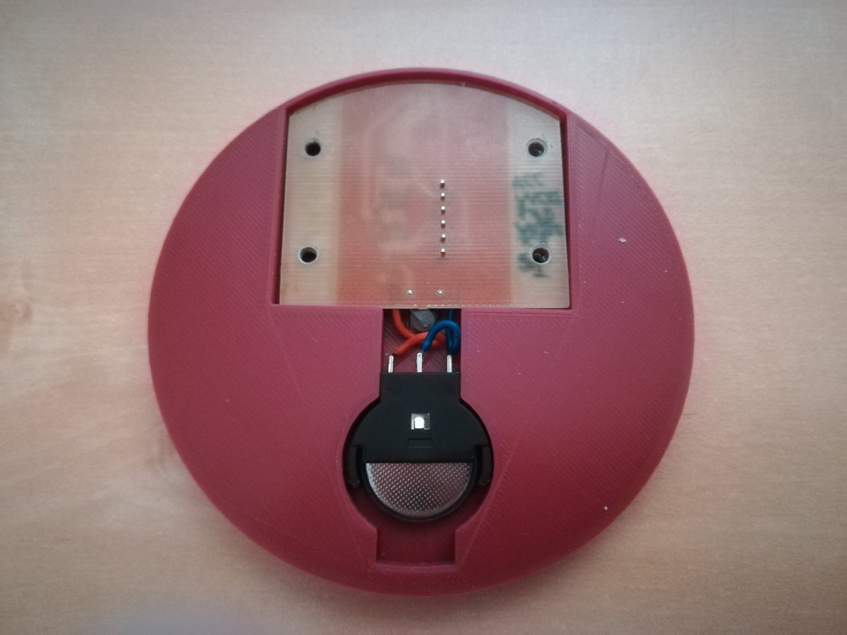
The schematics of the PCB did not change much, but I added connections to a 3V coin cell and redesigned the board so that I don't have to remove the ISP header. This is incredibly handy when testing the firmware. Milling and soldering was a breeze with laser cut stencil, solder paste, and hot air gun.

For the firmware, I switched to C++ instead of plain C. Especially since C++11, it provides a couple of handy improvements over C. In terms of functionality, there are a couple of changes as well. The most striking differences to the first iteration are:
- using the watchdog timer instead of timer 0 to trigger the ADC.
- averaging across multiple measurements to stabilize the temperature readings.
- measuring VCC to improve accuracy of temperature readings.
- automatic turn on/turn off mechanism depending on temperature.
- exponential increase of time waited between temperature readings. Using the watchdog timer allows the MCU to enter power down sleep mode, which is more energy efficient than the idle/ADC noise reduction sleep mode.
Let's have a look at some of the more interesting changes. The full code can be found in the download section. First, some notes on what we actually measure and how to derive the temperature from that value. The 10-bit ADC of the ATTiny45 actually returns values according to the following equation:
Remember that we used the voltage divider as input. Thus, we can calculate as
where is the balance resistor (here, 24kΩ). Since that value is dependent on VCC, and VCC will drop when the battery gets empty, we need some way to incorporate it's value into the equation. Fortunately, the ATTiny45 is able to measure it's own VCC by comparing it to an internally regulated 1.1V. We only need to configure the ADC accordingly. Then
and we can calculate the resistance of the thermistor as
Knowing the resistance of out thermistor at a certain temperature, we can determine whether it currently is hotter or colder than this temperature, which is good enough for my coaster. To go even further and determine the temperature exactly, we could employ the Steinhart-Hart equation, which relates resistance of a NTC to its temperature.
The equation relates two integer values to another integer value, which should be fairly accurate. However, there is a problem - we don't have the required precision. We would need 64 bit integers to reliably calculate R(T), otherwise we will get over- or underflows during computation and the result will be wrong. Using 64 bit integers would require at least 16 registers, and I don't want to use that many. So instead I will use the following equation:
This equation has the added benefit that the results fit in a single 8 bit value. The inaccuracies introduced through the integer division on the right side should be smaller than the inaccuracies due to the measurements.
The actual implementation in C++ is straightforward:
uint8_t r = static_cast<uint8_t>(
    (((uint32_t)D_T * D_VCC) << 8)
    / ((((uint32_t)1 << 20) - D_VCC * D_T))
  );
D_T and D_VCC are the ADC measurements for the thermistor and VCC, respectively.
They are 16 bit integers, so casting to 32 bits is necessary to ensure correct computation.
Values are stored in a ring buffer, which is a templated C++ struct:
template<typename T, uint8_t N>
struct RingBuffer {
  T buffer[N];
  uint8_t next = 0;
  uint8_t n = 0;

  T mean() {
    uint32_t sum = 0;
    for(uint8_t i = 0; i < n; i++) {
      sum += buffer[i];
    }

    return static_cast<T>(sum / n);
  }

  void push(T v) {
    buffer[next++] = v;
    next %= N;
    if(n < N) n++;
  }
};
The template arguments are resolved at compile time; thus I can create a ring buffer with 6 entries, each of which is a unsigned 8-bit integer with this line:
RingBuffer<uint8_t, 6> adc_buffer;
The mean of the ring buffer is compared with thresholds that are determined from user-defined resistance values and calculated at compile time with a C++11 constexpr function:
constexpr uint8_t threshold(uint32_t r_t, uint32_t r_b) {
  return (r_t << 8) / r_b;
}
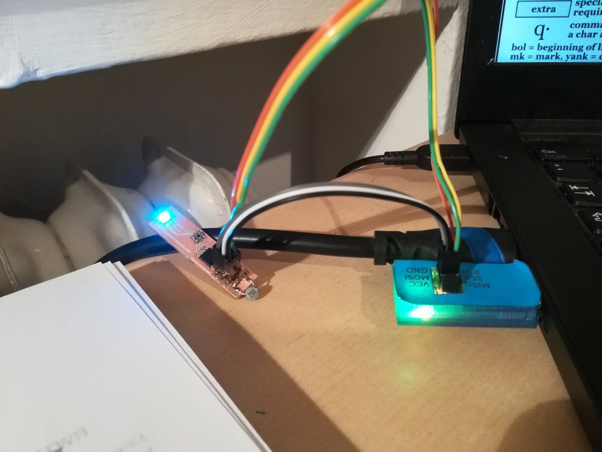
I programmed the board with avrdude and my FabISP.
And here's a video of version 2: