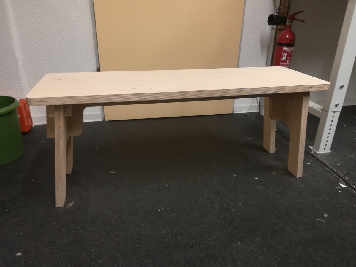
This week, we used a CNC mill to make something that's big and needs to be cut precisely. In my case, I built a bench out of three centimeter thick plywood that can be assembled without any screws or glue. The bench is about 120x45x40cm, but the design is parametric and should be adaptable to different sizes and material thicknesses.
Things I used to make this
Since the bench is made completely out of wood, this list is rather short:
- wood (I had 250x250x3cm plywood, but anything large enough to cut out all of the pieces should do)
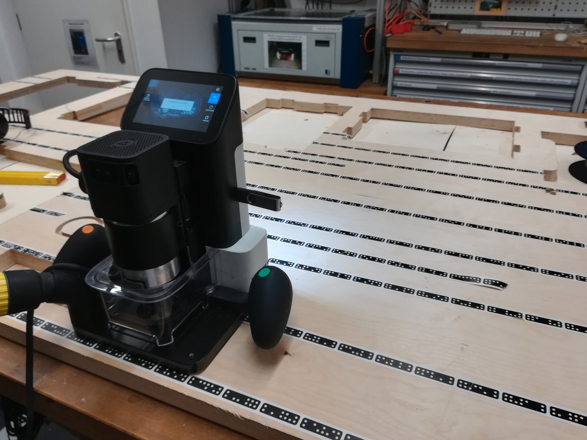
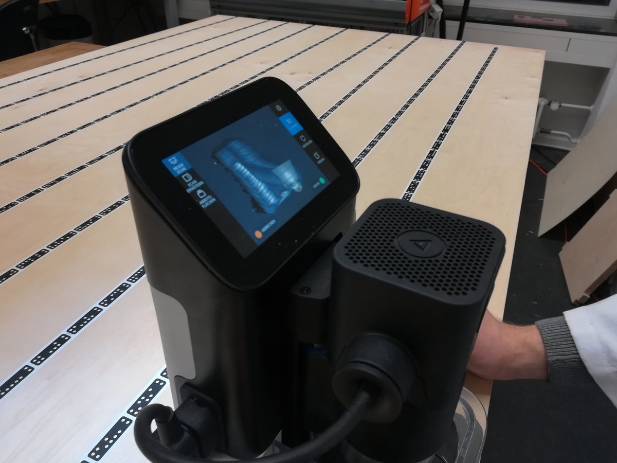
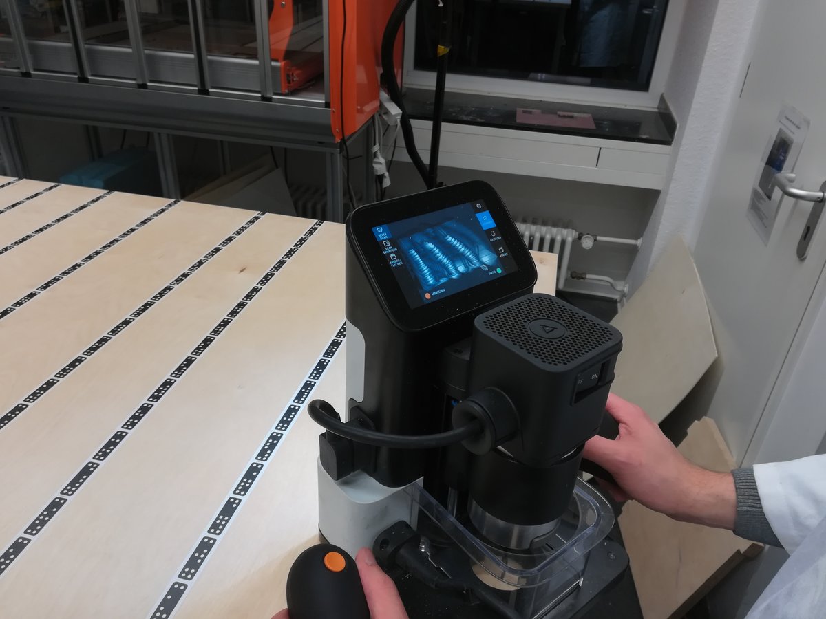
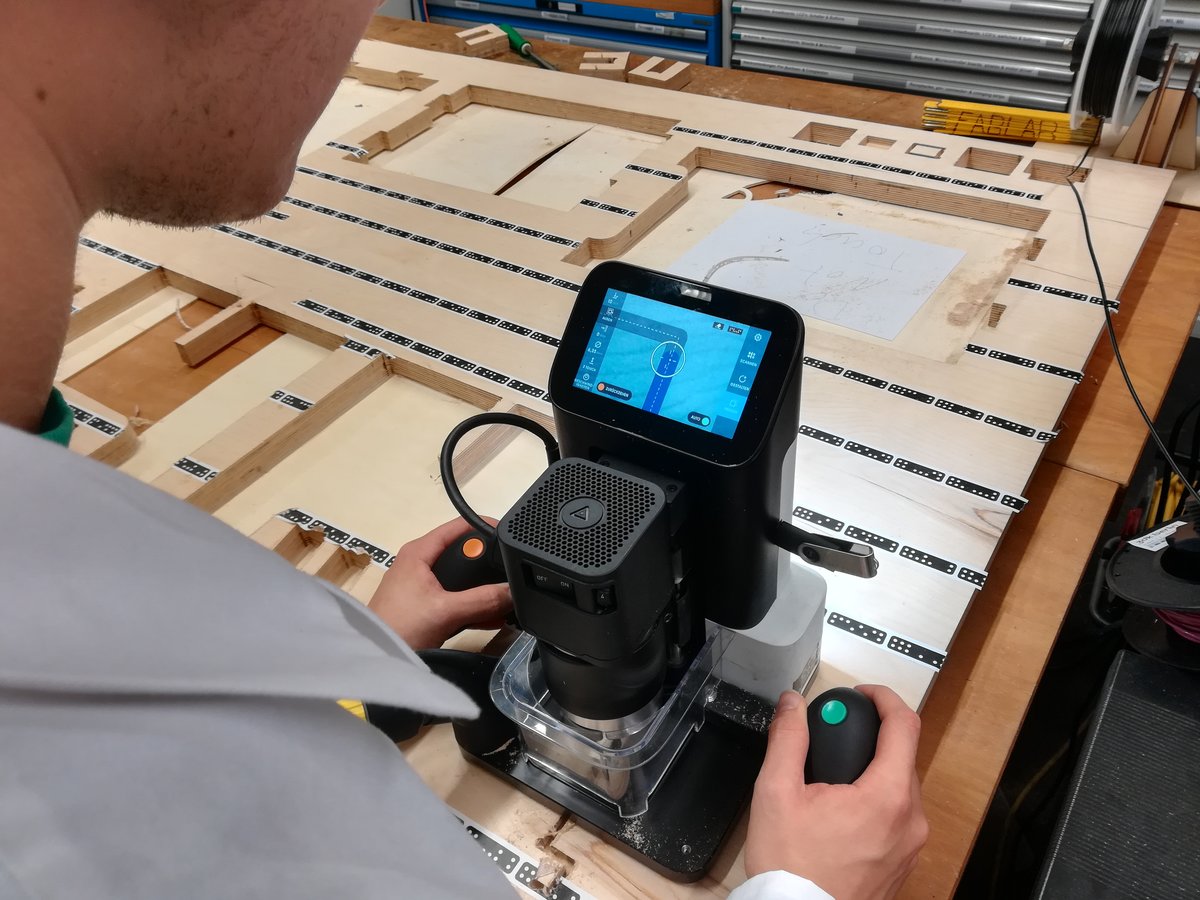
- a CNC mill (I used the Shaper Origin, which is a handheld CNC mill capable of operating on arbitrarily big areas)
- a couple of files and sanding paper
Designing
I made the design in FreeCAD, an open source CAD software. The bench consists mainly of four parts: the upper plank to sit on, two legs, and one piece of wood perpendicular to both the legs and the upper board, which holds everything together. I had to additional parts to hold the legs in place, since they are not orthogonal to the sitting plane, and our CNC mill can only cut perpendicular to its movement plane.
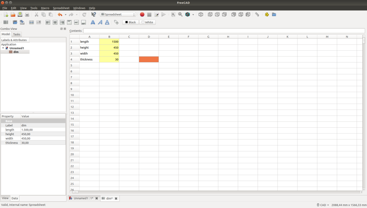
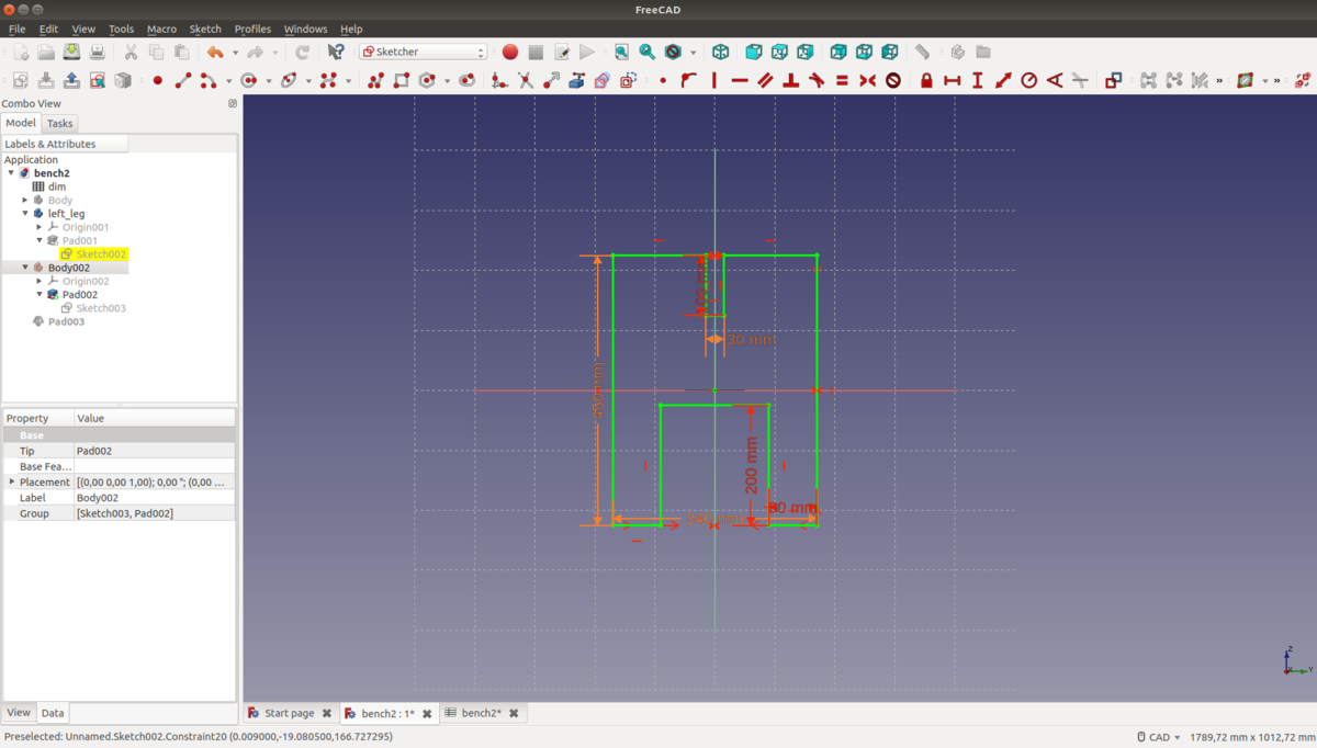
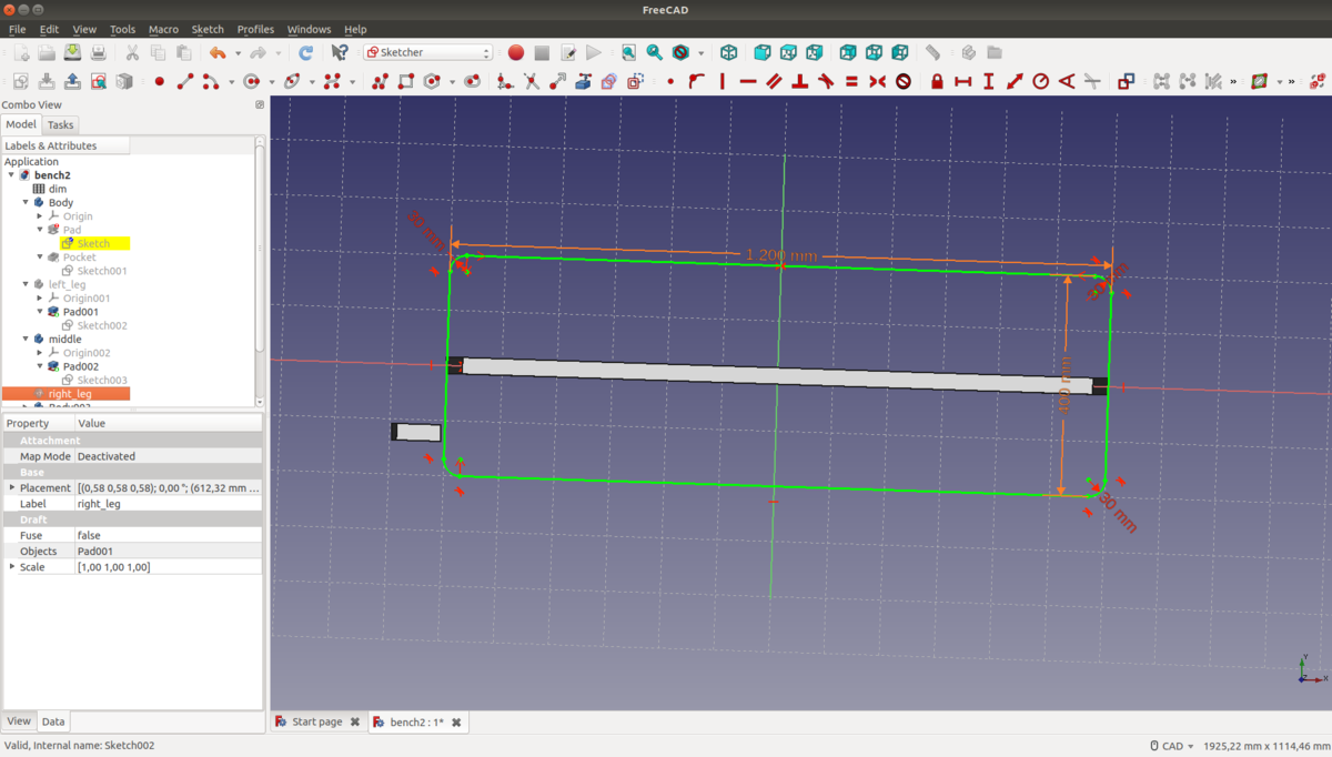
In FreeCAD, the available tools are separated in different groups called workbenches. To design the different parts individually, I used the Sketcher, Part Design and Part workbenches. In order to make the design parametric, I created a single spreadsheet that contains the adjustable parameters such as the desired length, width, and height of the bench as well as the thickness of the use material.
Designing individual parts with sketches
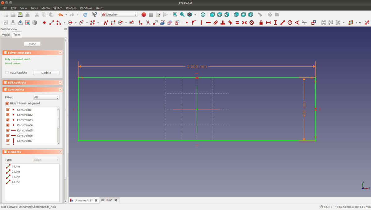
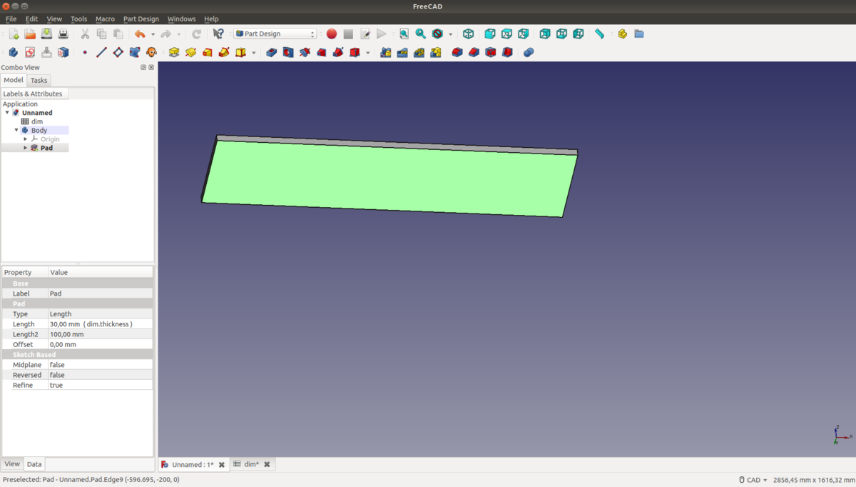
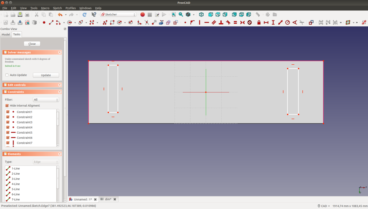
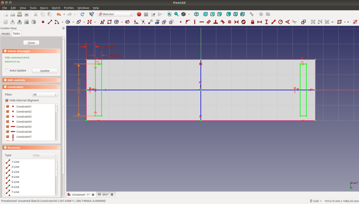
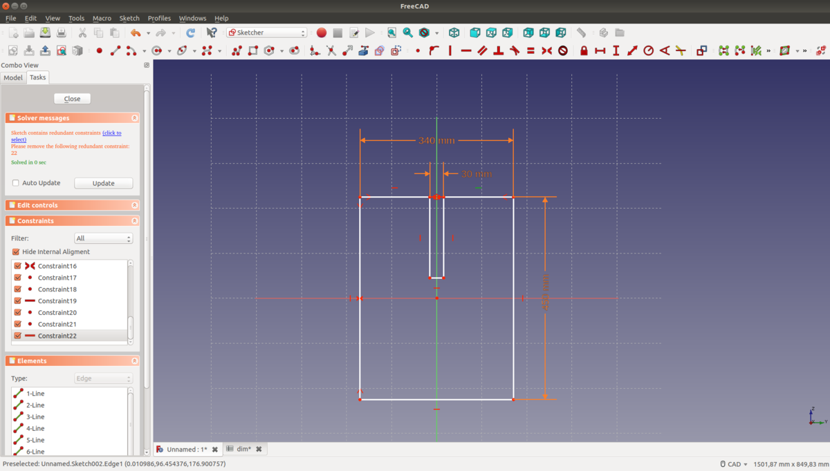
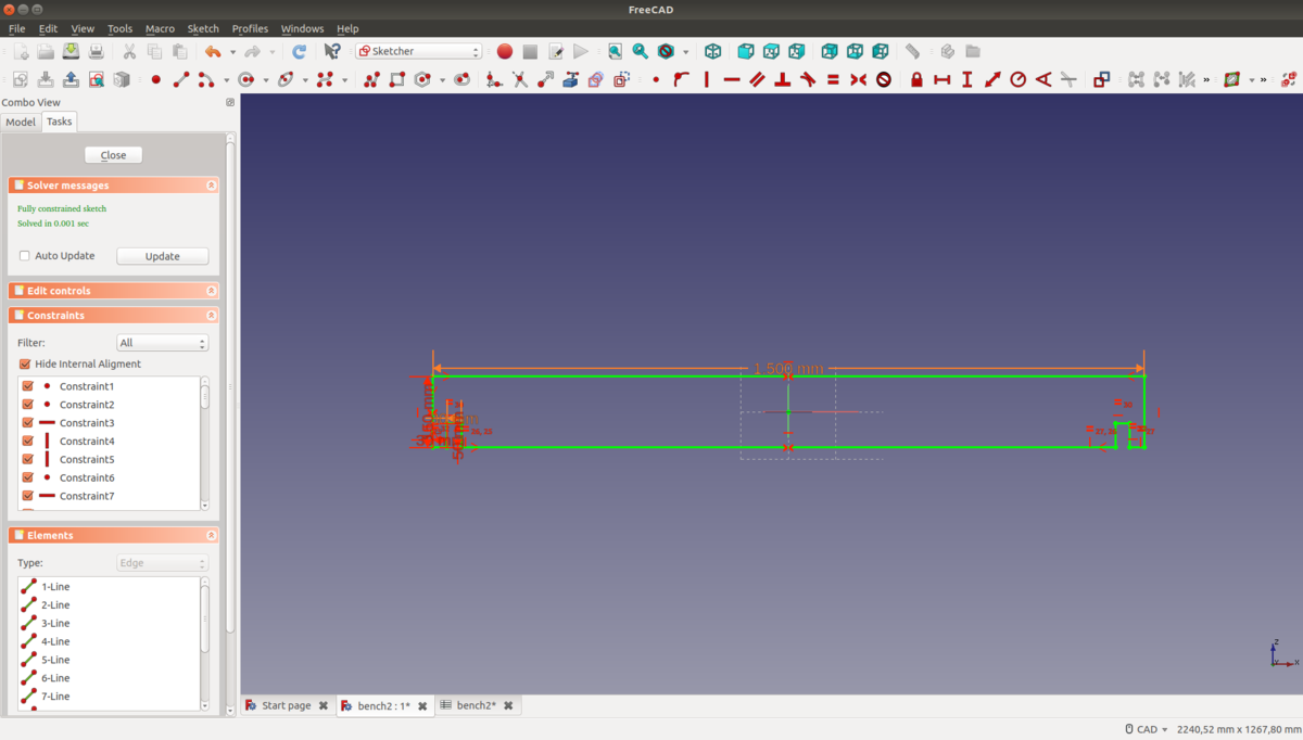
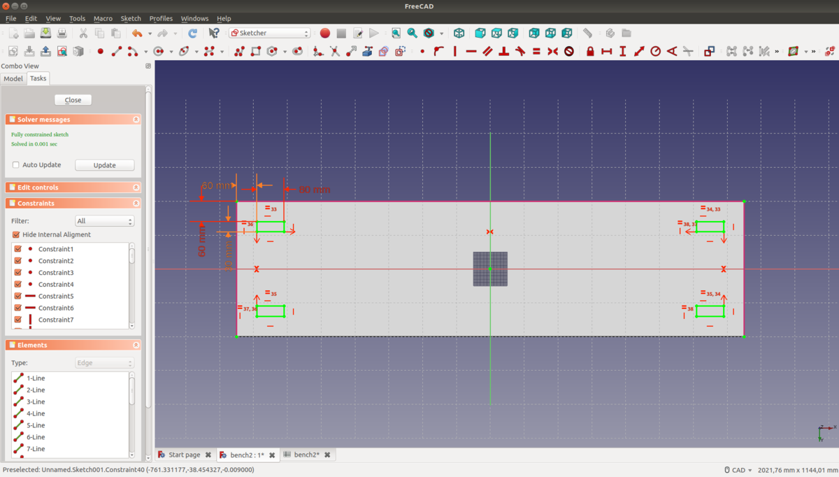
I started with the board to sit on. This is basically just a plain rectangle with holes to put the legs into. With the sketch tool, we can create constrained 2D sketches which can be turned into solids afterwards (for example, by raising them out of the sketching layer, rotating them, or subtracting material from the solid beneath them). Constraints enforce specific properties of the objects they are applied on (horizontal or vertical lines, for example). For all numbers that specify some property of an object (or constraint), it is possible to enter a formula instead of a fixed number. Object properties can be referenced in these formulas, making it possible to construct objects with rich parametric interdependencies.
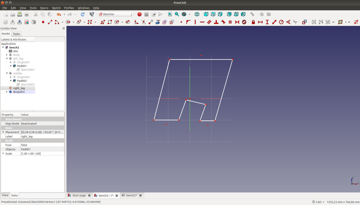
Next, I designed the legs. Again, I created a sketch of their profile and extruded the sketch to form a solid.
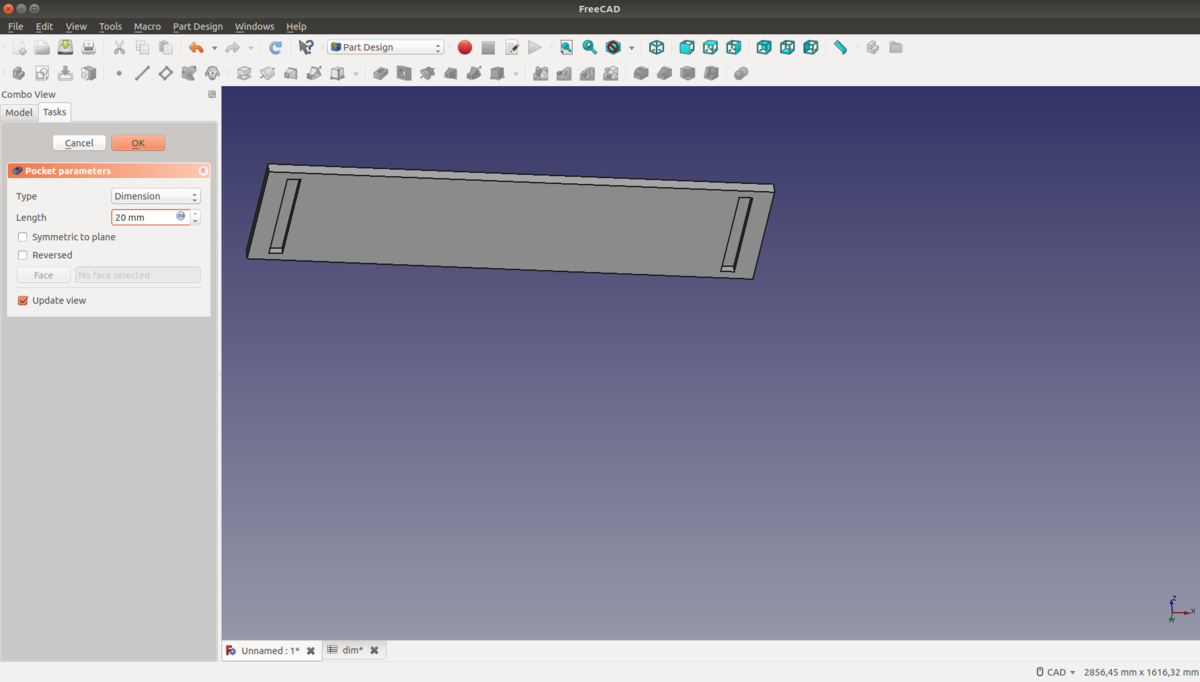
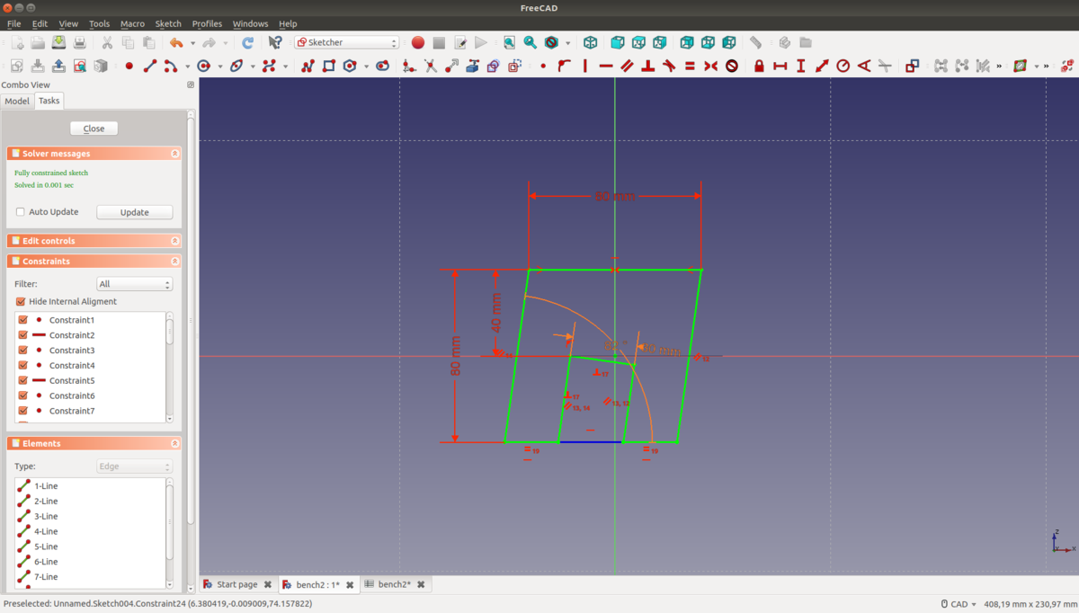
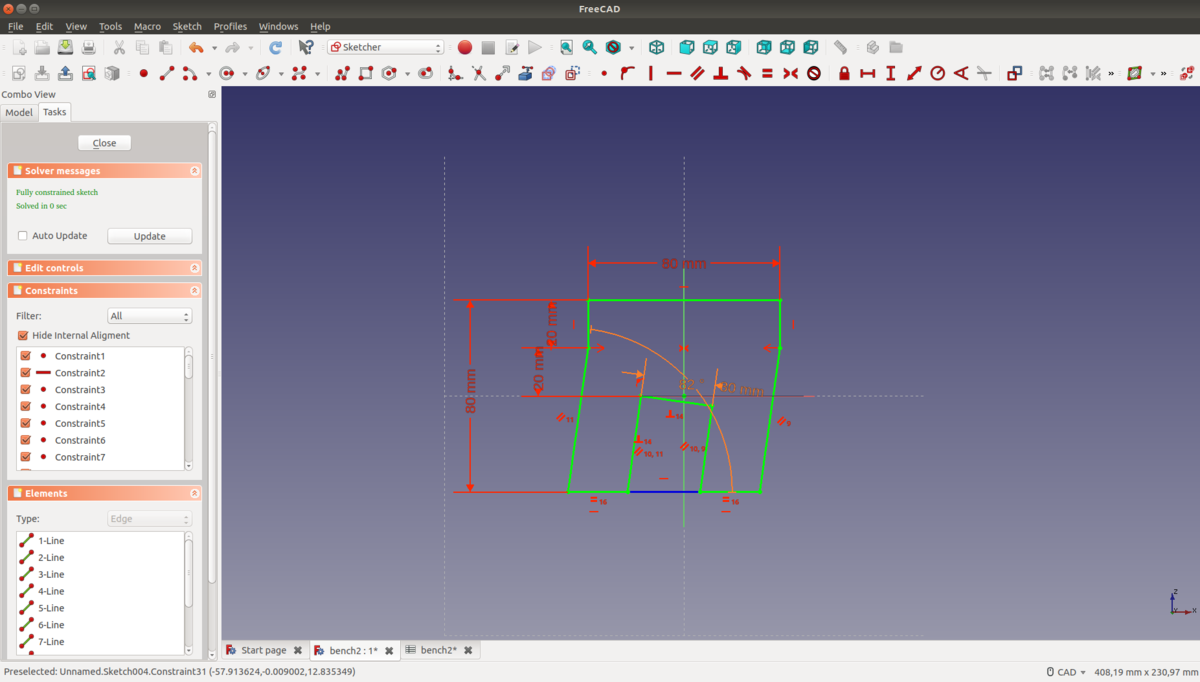
The design of the board in the middle took me a little bit longer, because of the angled slots for the legs.


Now I have angled legs, but I can't make angled cuts with the CNC mill in our lab. And I don't want to leave the legs as they are, because they are not that stable. Dang. So I have no choice than to add some kind of adapter between the board to sit on and the legs.

Phew! That's it for the design part. Now on to milling it, and hoping that everything will fit. Spoiler: it didn't, but I noticed early enough to make changes to the design. Which was easy, because it is parametric. The wood sheets were not exactly 3cm thick, but 2.9cm.
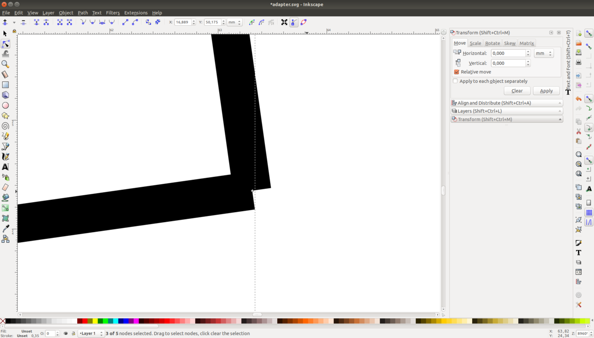
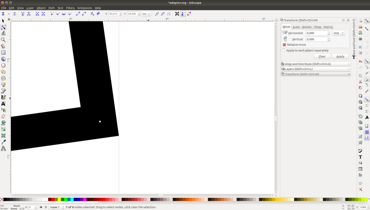
Exporting profiles to *.svg
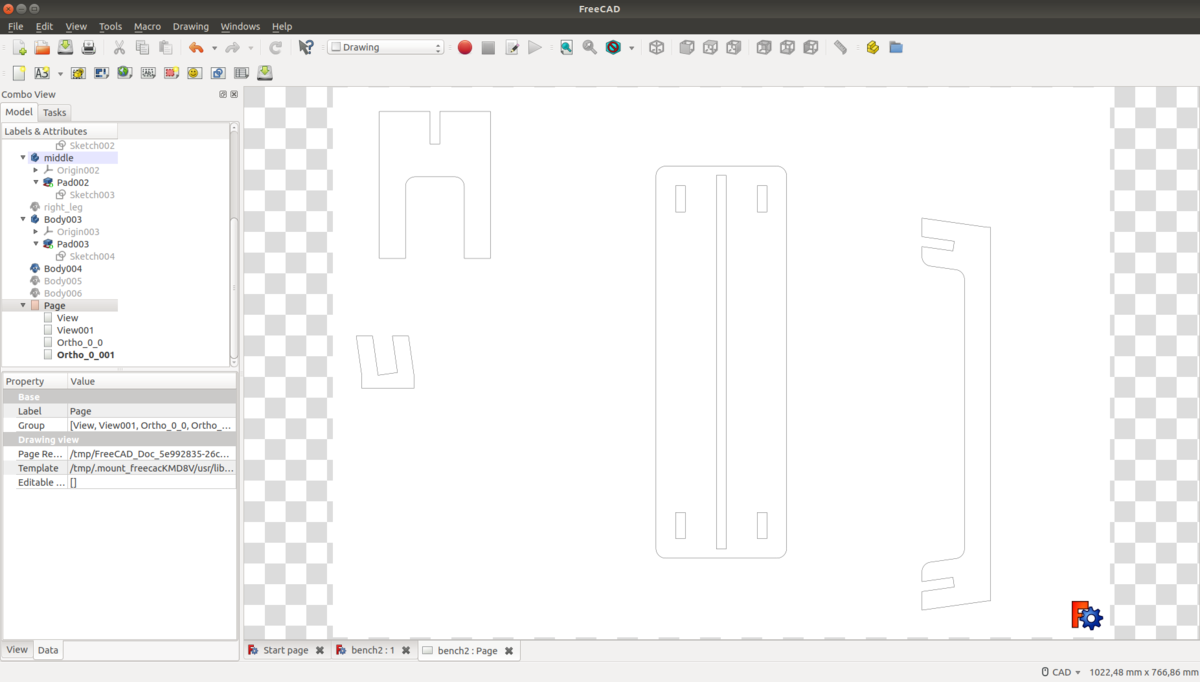
Actually, before milling it, I have to export it as a vector graphic. To this end, I created a drawing in FreeCAD that contained orthographic projections of the parts and exported that as an *.svg file. Unfortunately, the lines in the exported file were not connected, which led to problems with the CNC mill, so I had to edit them manually in Inkscape.
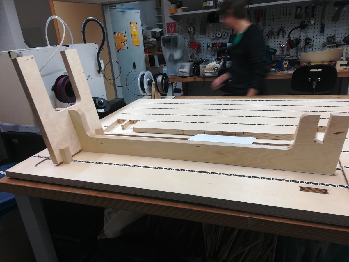
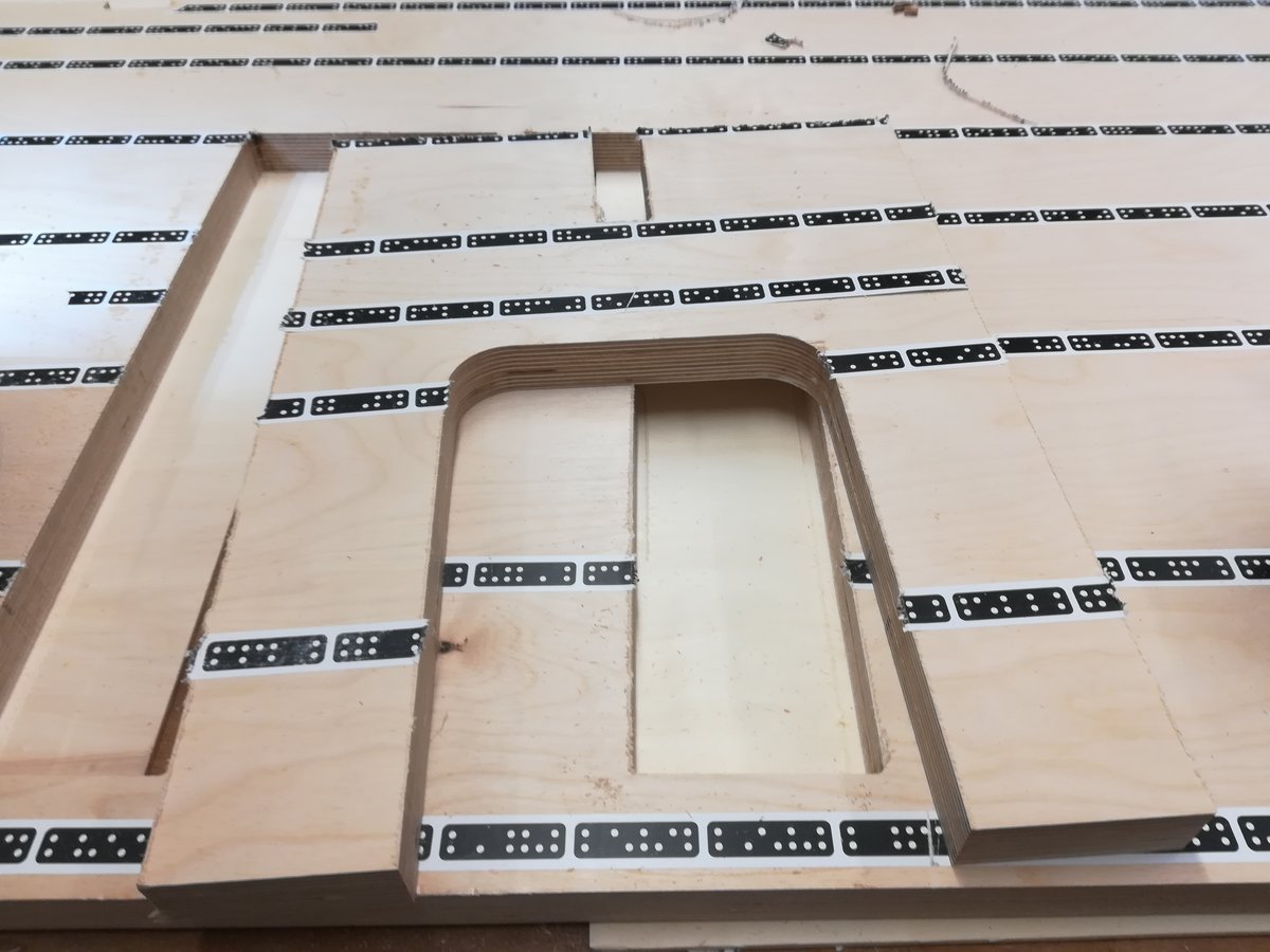
Cutting
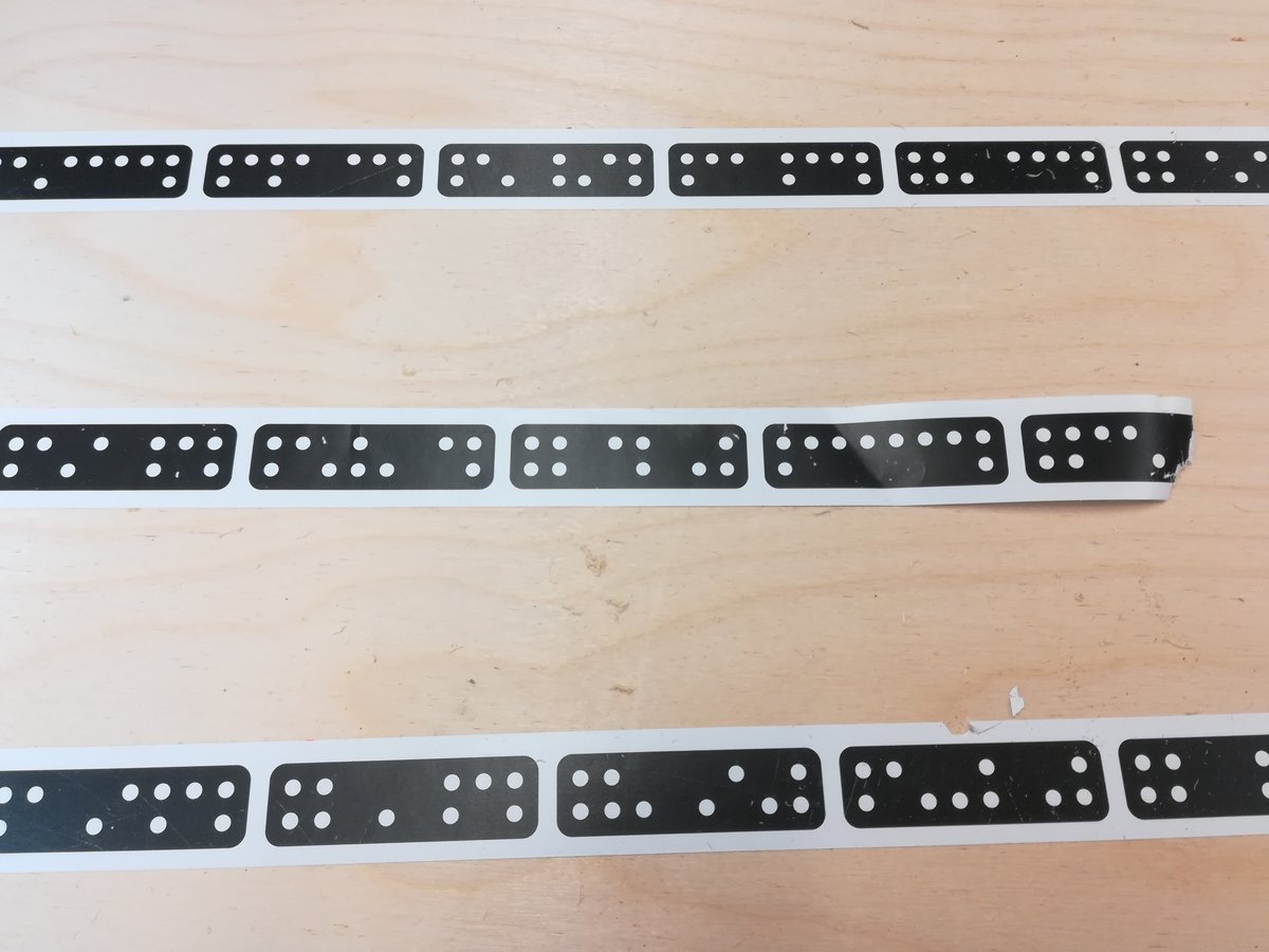
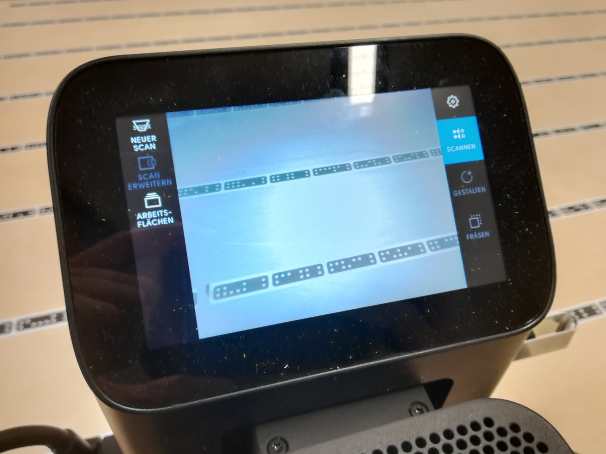
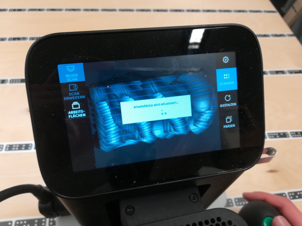
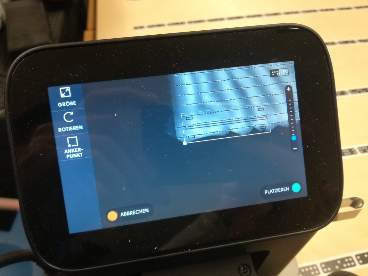
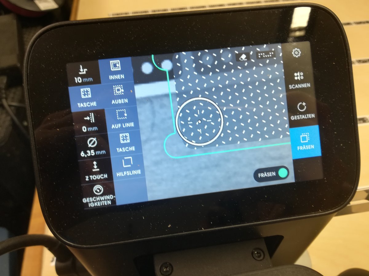
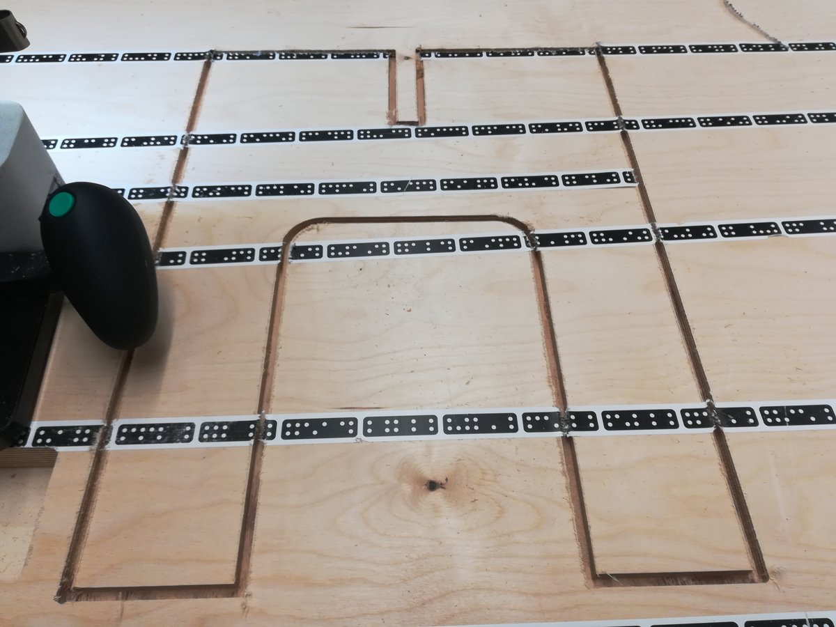
For this assignment, we were able to use a hand held CNC mill. Using tape with special visual markers (called shapertape), the mill is able to locate itself on a plane. As input, it requires a vector graphic of a shape that is to be cut. Parameters like depth and cut type (i.e. whether to cut on the inside, outside of the shape or on the line) can be encoded in the graphic via colors, but can also be set on the machine. The shape is then placed somewhere on the plane and the operator of the machine has to move along the lines; an indication of movement direction is shown on the display. The mill automatically corrects deviations from the path with the moveable drill head. If it detects that it cannot correct some motion, or cannot locate itself due to insufficient visible tape, the drill head is automatically retracted.
Assembling
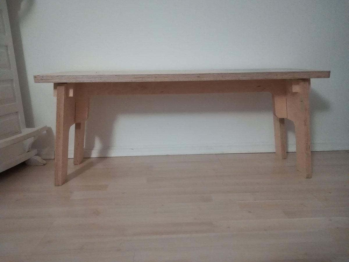
Since there are only eight parts, and no screws, complex joints, or particularly small pieces, the assembly of my bench was a breeze.
Well, except for the middle part, which did not fit as well as the other parts because the wooden board from which I cut it was not straight.
But with enough violence patience and a bit of sanding paper and filing, I managed to fit it in.