In the first week of the Fab Academy, we were introduced to digital and personal fabrication, the ideas and visions behind Fab Labs, and the Fab Charter. We had time to think about what we expected to learn in the coming weeks and months, and how we plan to implement these skills. In particular, our assignment was to sketch an idea for a final project, which should ideally incorporate all design & fabrication techniques that are presented during the course.
I decided to attempt building a three-axis gimbal for the Raspberry Pi Zero. The scope of the project is easy to grasp: using three motors, an orientation sensor, and a circuit controlling the motors depending on the orientation of the sensor, stabilize the camera along all three rotational axes. Implementing this functionality, however, is far from easy. I have to design a frame holding the camera and the other electronics, a motor control unit, as well as a circuit measuring and computing the current orientation of the camera. Careful planning and fine tuning of the mechanical parts, designing advanced electrical circuits, writing and adjusting efficient control mechanisms, and finally integrating all components together to create a well-working system is probably one of the most ambitious projects I have undertaken so far. I'm looking forward to beat this challenge.
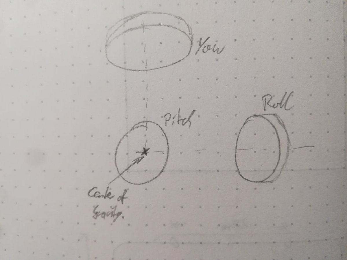
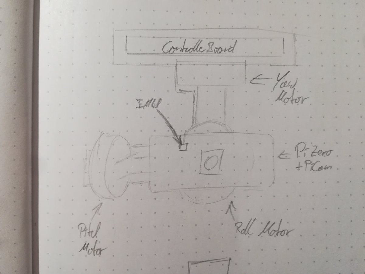
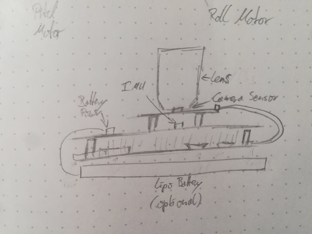
The following sketches illustrate my ideas on the overall design. First, the general principle: three motors with orthogonal turning axes manipulate the orientation of the camera, whose center of gravity has to be located at the intersection of the axes. Then, the frame. In its simplest form, has a containment for the main board (where e.g. the motor driver ICs and main processor are placed), one arm to pan around, and one arm to alter the pitch of the camera. The Camera is directly attached to the motor controlling the roll axis. Finally, an extension board for the pi houses the inertial measurement unit (IMU), as well as a processor that reads the sensor and power management electronics. The Camera is mounted onto this extension board. Ideally, I would like to include the option to power the pi from a LiPo battery attached to the back instead of running a cable from the main board to the extension board.
For this project, I need at least
- A Raspberry Pi Zero W
- A camera for the pi
- PLA/other 3D printable material thats sturdy enough for the frame
- Three small motors
- probably a lot of electrical components that are not in the standard/not in our Fab Lab inventory.
You can read more about my motivation and my journey to a finished final project on my final project documentation site and on the project development page.