Final project development
Week 20
ASSIGNEMENT
- Evaluate project plan
- Apply time management techniques
- Summarise and communicate the essence of a project
What is the deadline? How much time do I have left?
I have 15 days to do the project.
The final presentation date is June 15th.
What tasks have been completed, and what tasks remain?
It is difficult to answer to this question at this point.
Project and process documentation was done after the final presentation...
I will describe how I managed the time on this project:
To arrive in time and to be sure that the project works, I started with the part I was less experienced:
Electronics and embedded programming.
I told myself that by doing this, if the time for this part was longer than expected,
I could simplify the other parts, manufacturing, documentation ...
This strategy proved to be the right one for me.
It was also important to have the exact dimensions of the board
and to think carefully about its connections with the other elements of the project.
I had 7 days to finish the project: to design and produce the casing, the movie, the slide.
How will I complete the remaining tasks in time?
What I did every day was to review the project, the things to do,
and constantly see how to run the project to arrive on time.
Neil used the word triage,
This notion has been with me all the time for the duration of this part of the fabacademy.
The principle is to remain very flexible, at the same time to know where one directs precisely and to adapt permanently.
This way of managing time made me decide to change the electronic board,
because by looking at the time that remained for the project,
I did not see how I was going to quickly learn how to make an APP for a smartphone, using bluetooth serial communication,
even if I had approached that in one of the assignments(week 14).
I preferred to take another path, with the same project
and do it in a more traditional way: integrated buttons and screen.
I can always continue this project by improving it.
I think it was a good decision.
What has worked?
I believe that what worked well is precisely this way of working with time.
Denis was worried ... I was finally perfectly on time ...
We were ready with Nicolas for the final presentation...
We were perfectly on time, ready to unmute to present to Neil.
We had bad luck, on our network that did not work anymore ...
But that was impossible to predict ...
We have presented during the break, it was a great relief for us to present that day.
It is rather this posture to look daily at what has been done,remains to be done
and adapt to what is to be remembered.
See the schedule in its main lines and then :
adapt, adapt and adapt.
It must be said that when I was a student and afterwards in my professional life,
we regularly competed with a precise date and time of delivery.
So I had some habit ...
What has not?
Document while working. It's a hard habit to take, but it's probably a lot of interest.
Just in this short time, I preferred to focus on the project.
I did not anticipate the time for 3D printing and tested more materials that I did not know
Which is not a problem if we give ourselves the time to test.
I almost failed ...
Always have a plan B. Not sure of having always reasoned like that.
Little anticipation on material orders. I knew we had a lot of things in the lab,
that suppliers are not very far, but it was quite reckless ...
What questions still need to be resolved?
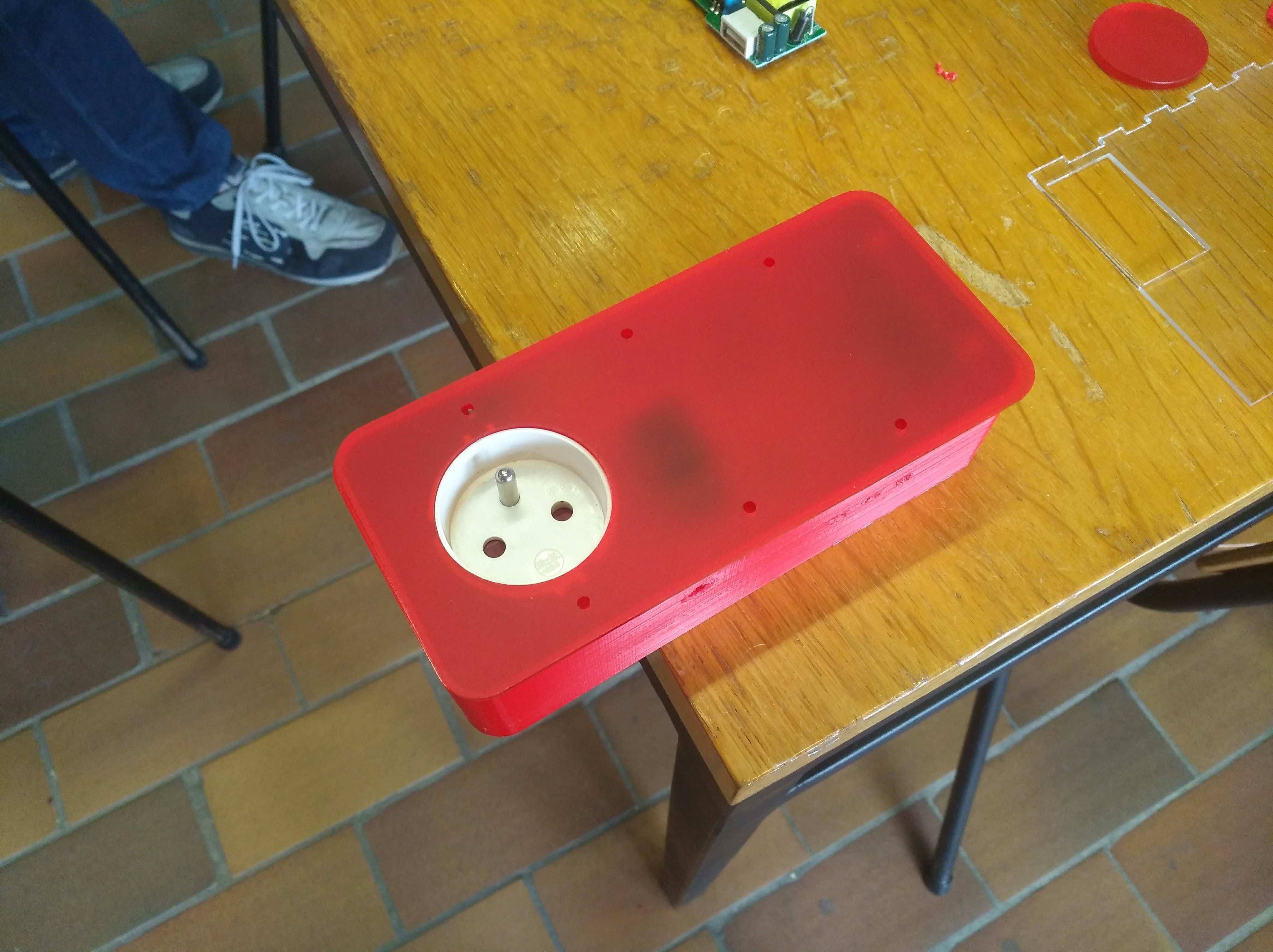
The tightness of the plug and buttons, not enough thought.
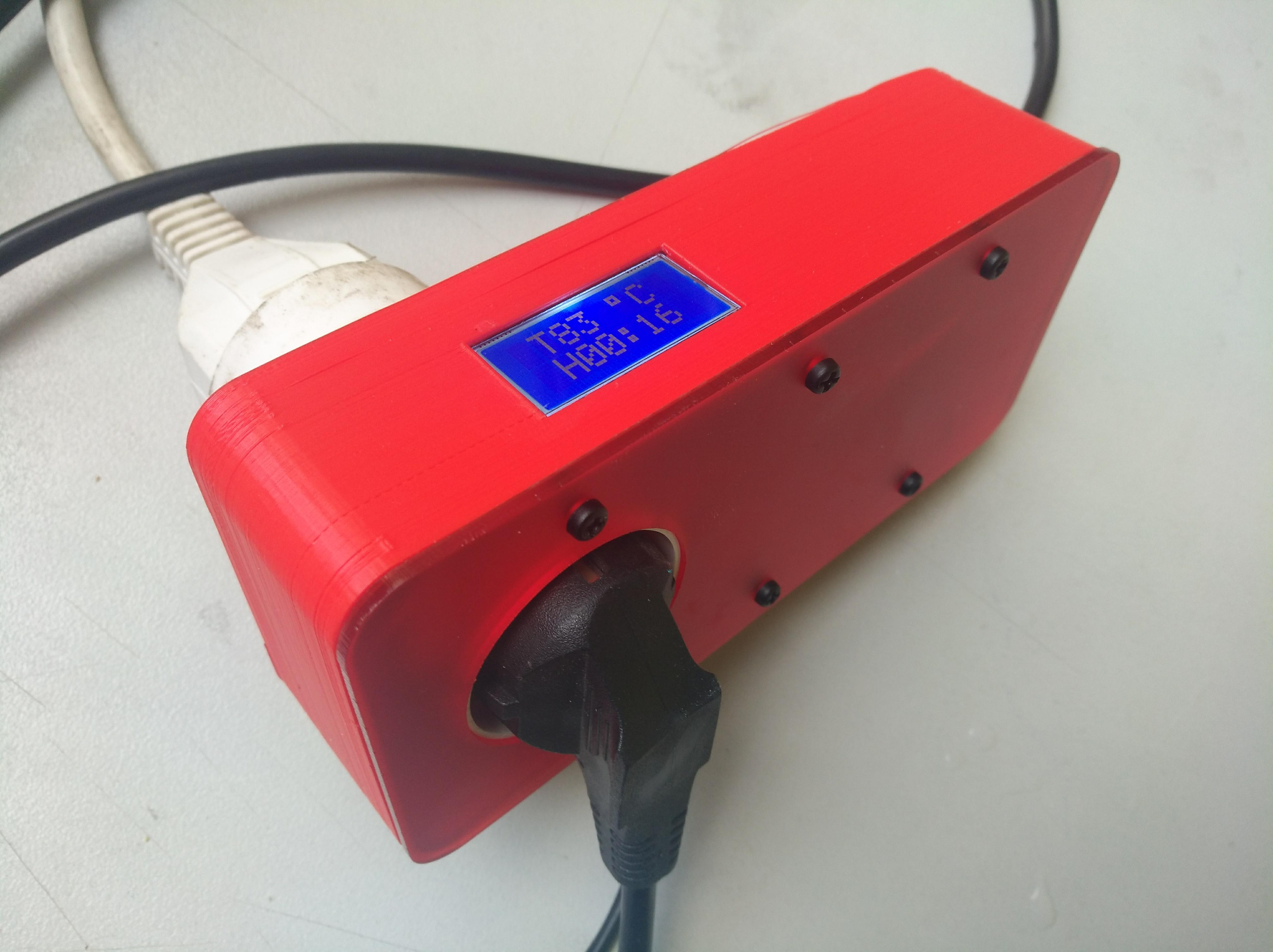
The screen, not very well placed, too small
Still a lot to improve...
What have you learned?
- Document the work you do, when you do it.
- Cut the project in pieces.
- Start with a simple thing and master it.
- Search on internet, lot's of people who have the same problem have already documented.
- Go search for external skills.
- Team working.
- Students are excellent teachers.
- Take advantage of short timing.
- Observe how others reason to be inspired by their logic.
- Look at the machines and imagine how they were made.
- Learn to do, without being afraid to fail.
- Listen to a coach, Yes Denis it is true ...!
- Look at what was already done.
- Work independently.
RESEARCH ON SOUS-VIDE AND JAR COOKING
When I began the project, I started doing tests of dishes, mostly soup.
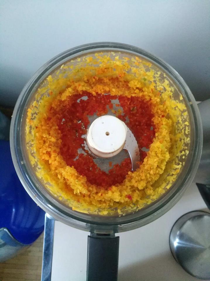
To speed up the cooking, I passed the vegetables in a mixer to reduce them to a rather fine piece.
I tested the cooking in a bottle of wine in a bain-marie
A manual air pump is used to evacuate the air from the wine bottle.
I wanted to test this to see if glass could be an alternative to the plastic bag in sous-vide cooking.
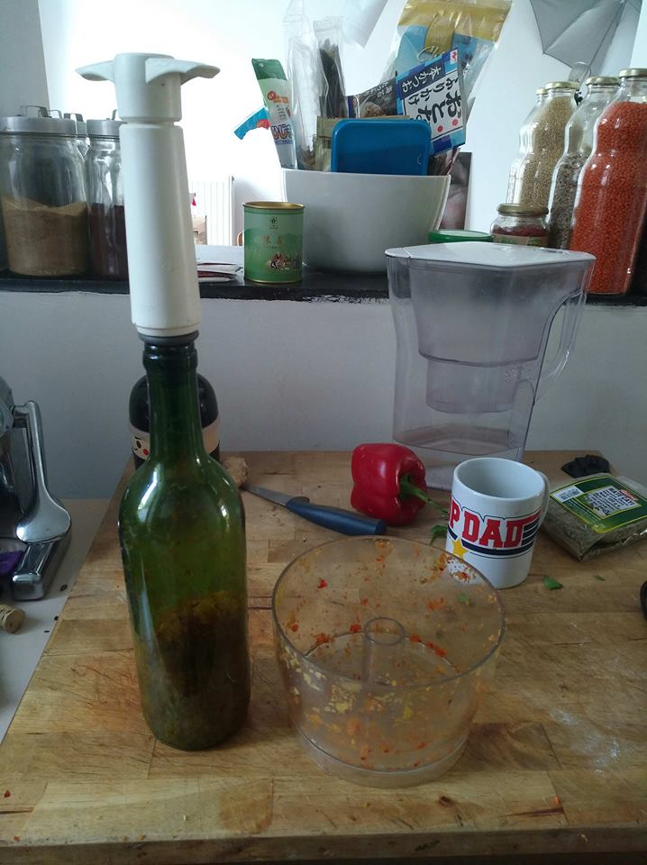
The result was inconclusive after 20 minutes of 100 degree water bath.
At 45 minutes the vegetables began to have a more melting consistency.
I started to focus on sous-vide cooking and was impressed by the amount of articles, books, videos about it.
Indeed, I always remained in the idea of setting up a simple process of soup cooking.
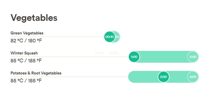
Vegetables cook perfectly between 82 and 85 degrees Centigrade in a bain-marie
This will depend on the size of the cut vegetable pieces,
the type of vegetables and the desired texture.
This technique has been used for many years by many starred chefs.
It seemed to me at first far from what I wanted to develop.
What I wanted was a simple way to cook
easy to reproduce for people who had little training in cooking.
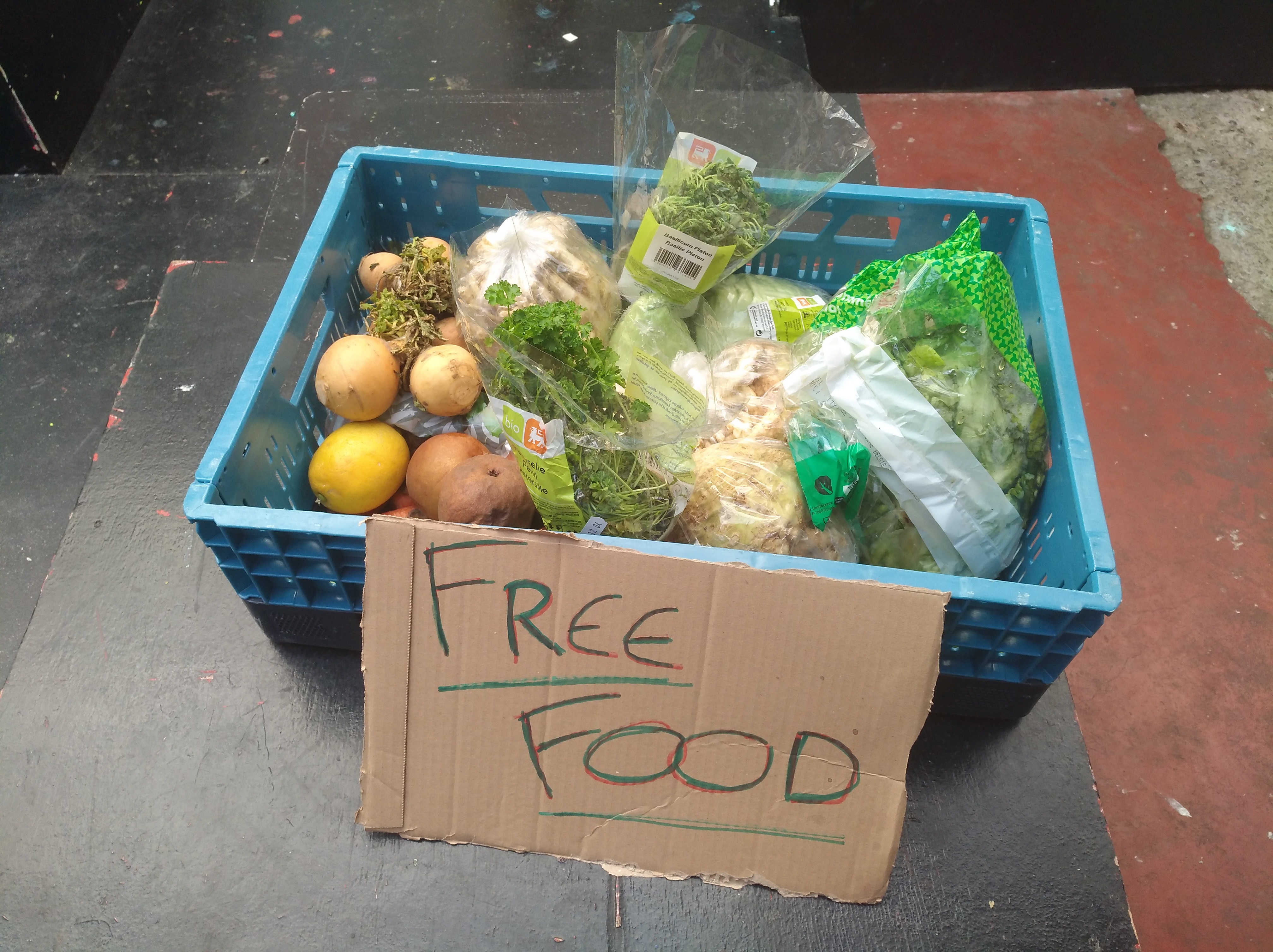
For example for people who want to cook with vegetables given away on markets.
The relationship between time and temperature was not obvious to me.
I went to see a professional cook to discuss it with him.
It gave me the chance to test a chicken breast cooking in an oven and cooking sous-vide.
The difference in taste and texture is striking.
flavourful and pleasant to chew cooked sous-vide and dry and almost cardboard baking with an oven.
He explained to me that time did not change the fact of having cooked food, but the texture.
The longer the cooking time, after the minimum time, the more the food will be tender.
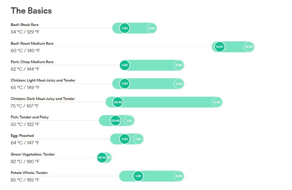
A crunchy vegetable will be cooked with the minimum time value indicated in the attached table for example.
It is also necessary to adapt to the size of the pieces so that the food could be cooked to the center.
Here we can see figures showing temperatures and cooking times.
The temperature range is 54 to 83 degrees centigrade.
In parallel with my tests and researches, I worked with my friend Isabelle to compare her way of cooking soups (which are delicious ...)
and mine, made with the same ingredients and cooked in a bain-marie.
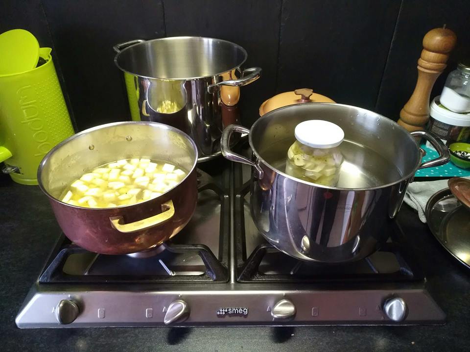
The taste was quite similar..
Even if the seasoning was quite difficult to achieve in a jar.
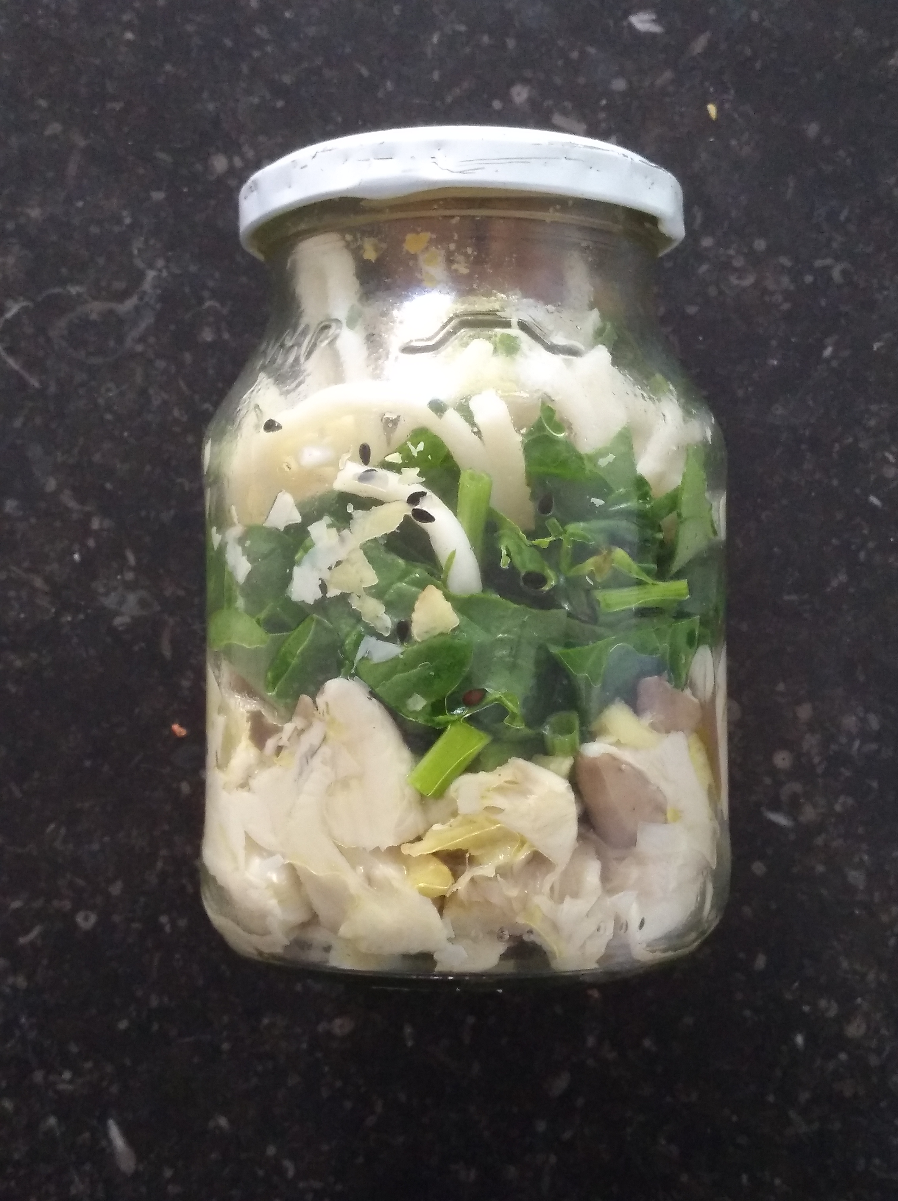
The cooking time has increased from 45 minutes in traditional cooking to 2 hours in a jar in a bain-marie.
I thought other people had probably tested cooking in jar.
In the USA, a type of jar is widely used for preserving food, jams ...
These are the Mason Jars.
I started to look at some websites and videos that speak of this way of cooking
It corresponds much more to what I wish: Cook with the least possible risk to health.
It goes through some strange projects, like this one: how to cook with a dishwasher.
to simpler projects like this one: 5 Easy Instant Soup Cups
I also found a vacuum cooker from Anova in a second-hand shop that I bought to test it.
Unconvincing actually.
WHO HAS DONE WHAT BEFOREHAND?
Commercial version
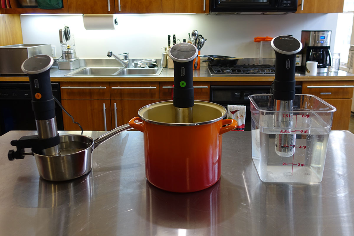
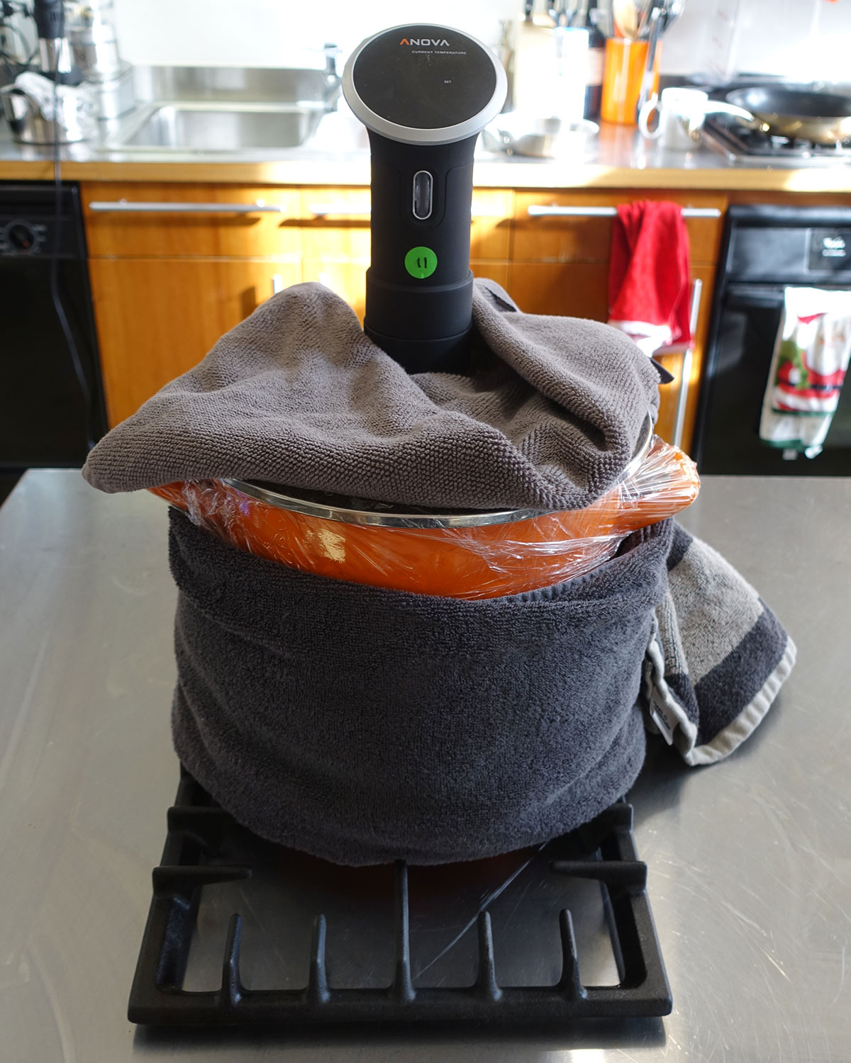
Anova
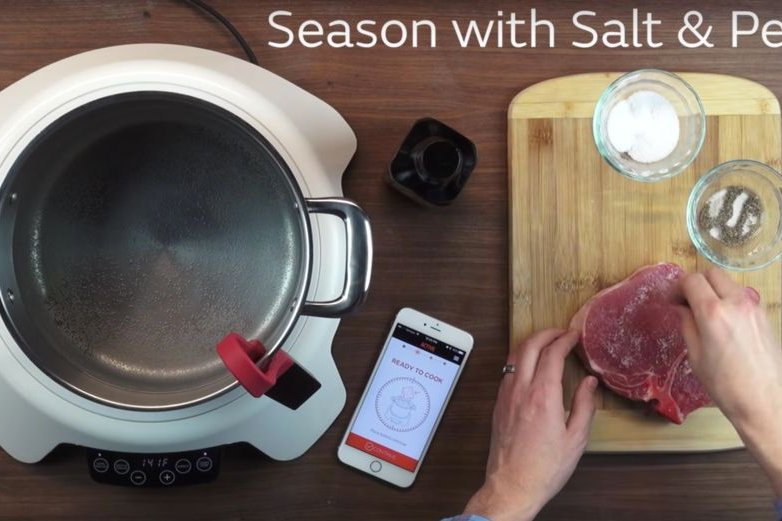
Paragon
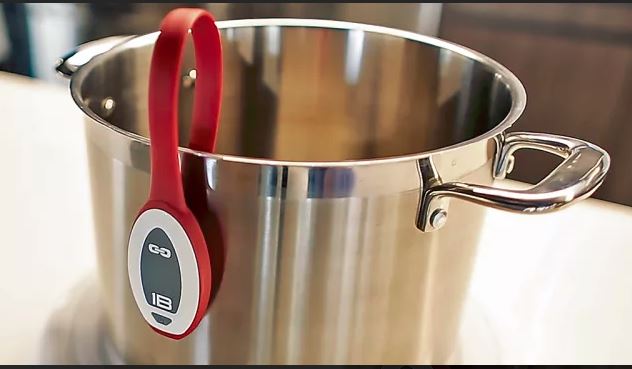
Gizmodo
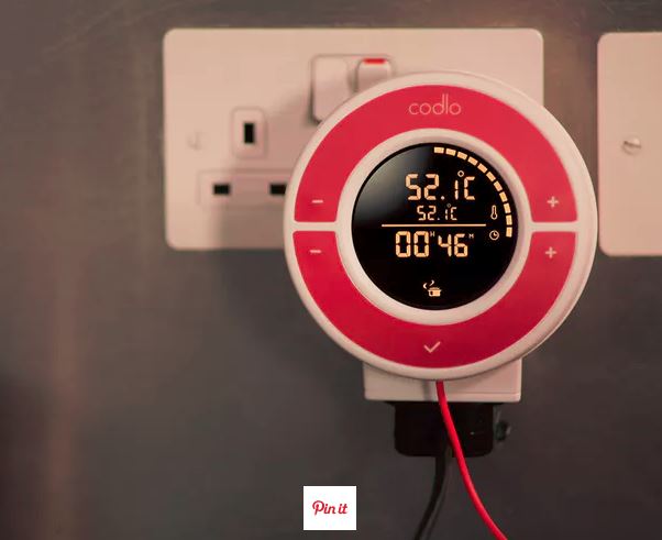
Codlo
DIY version
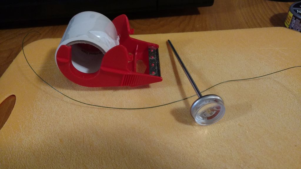
Sous-Vide-With-No-Special-Equipment
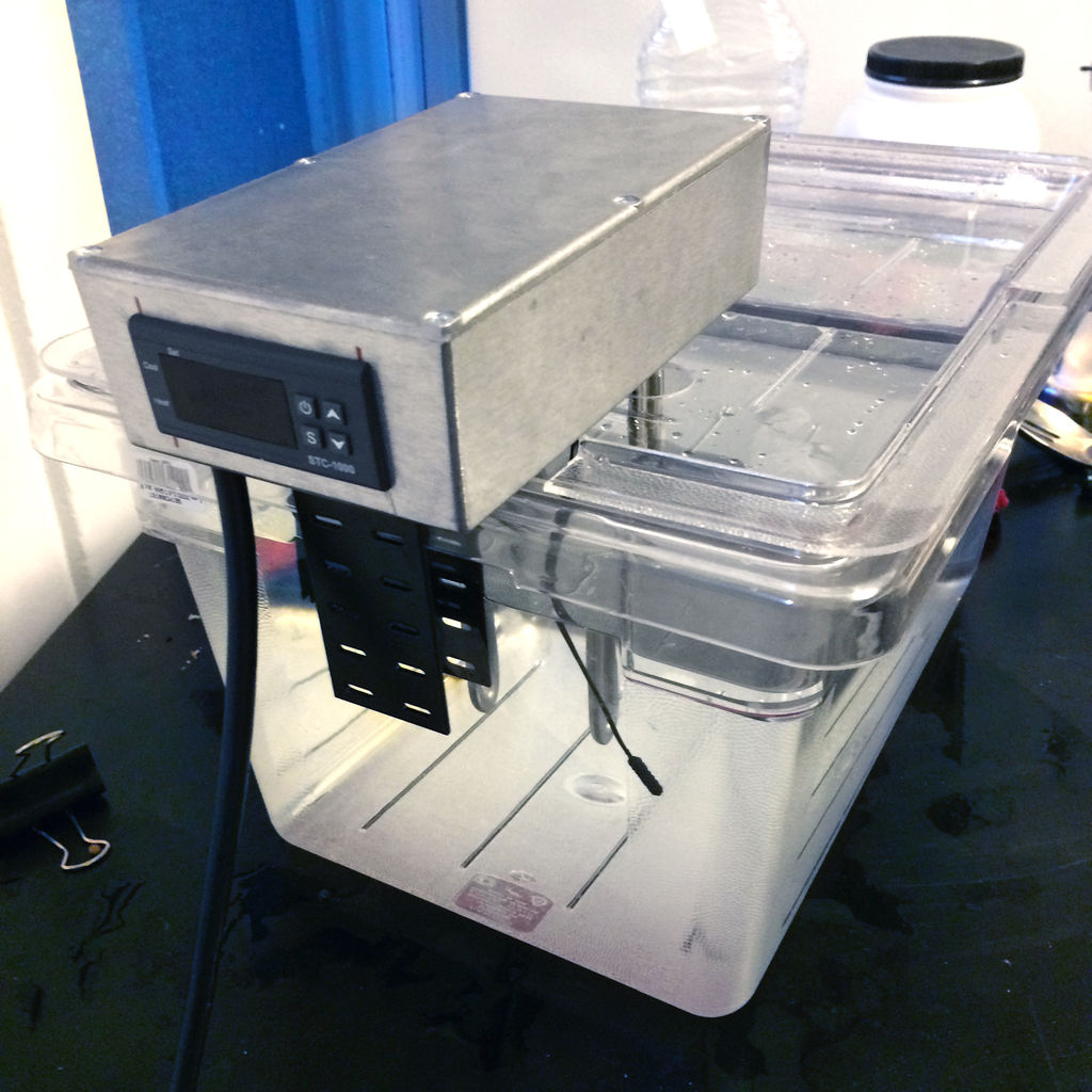
Premium sous-vide
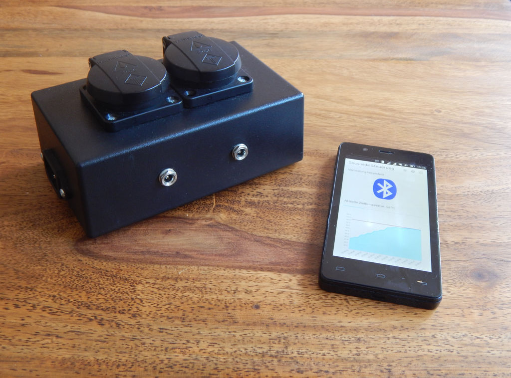
Sous-Vide-Controller
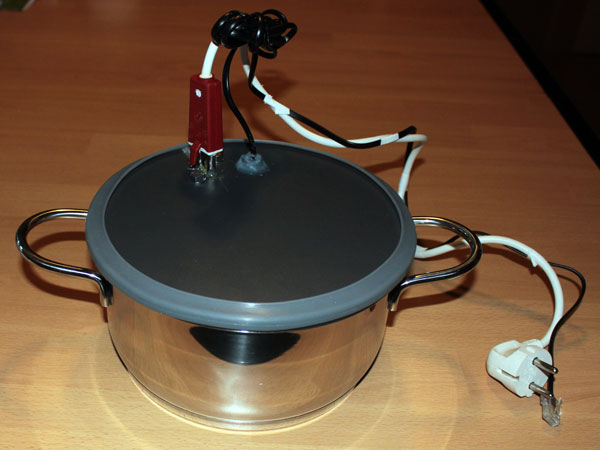
Garer
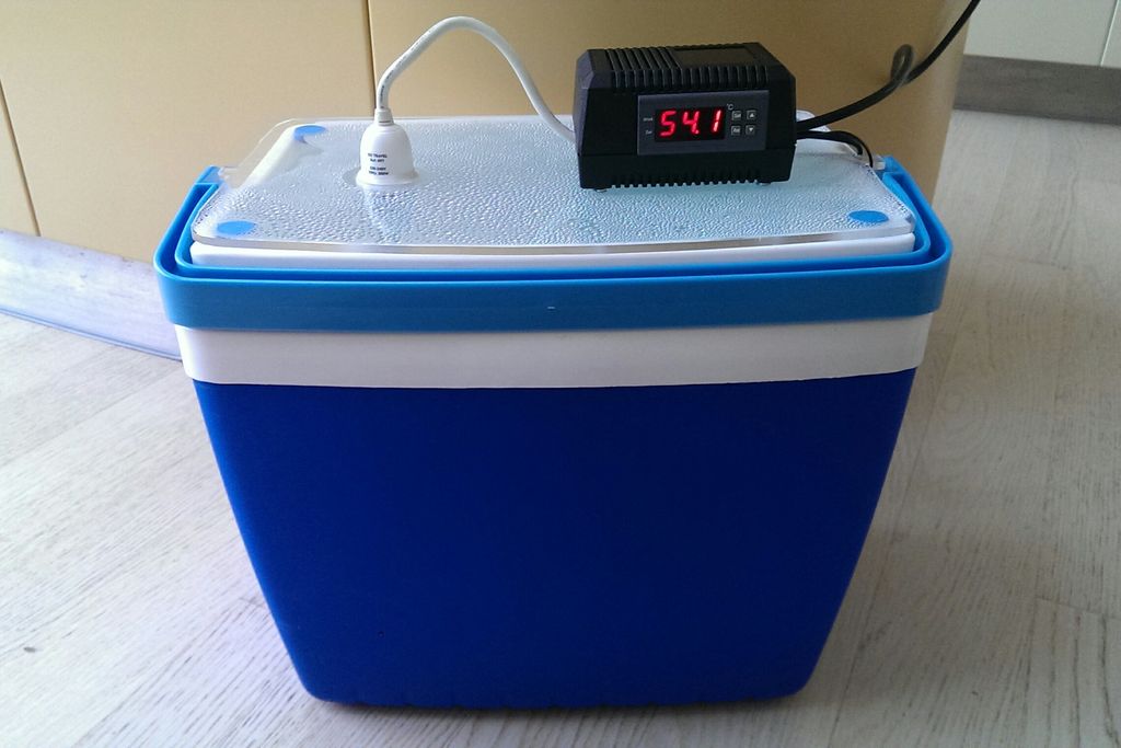
Sous-vide-cooker-yoghurt-incubator
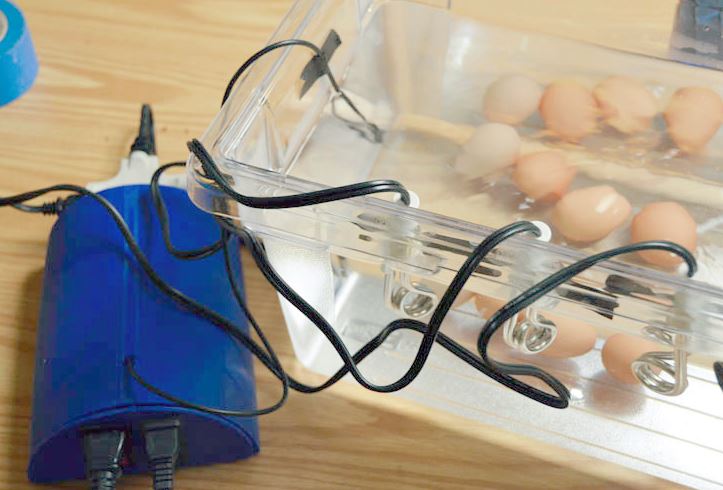
Sous-vide How to do almost anything
THE MAKING OFF
The final project I decided to do should :
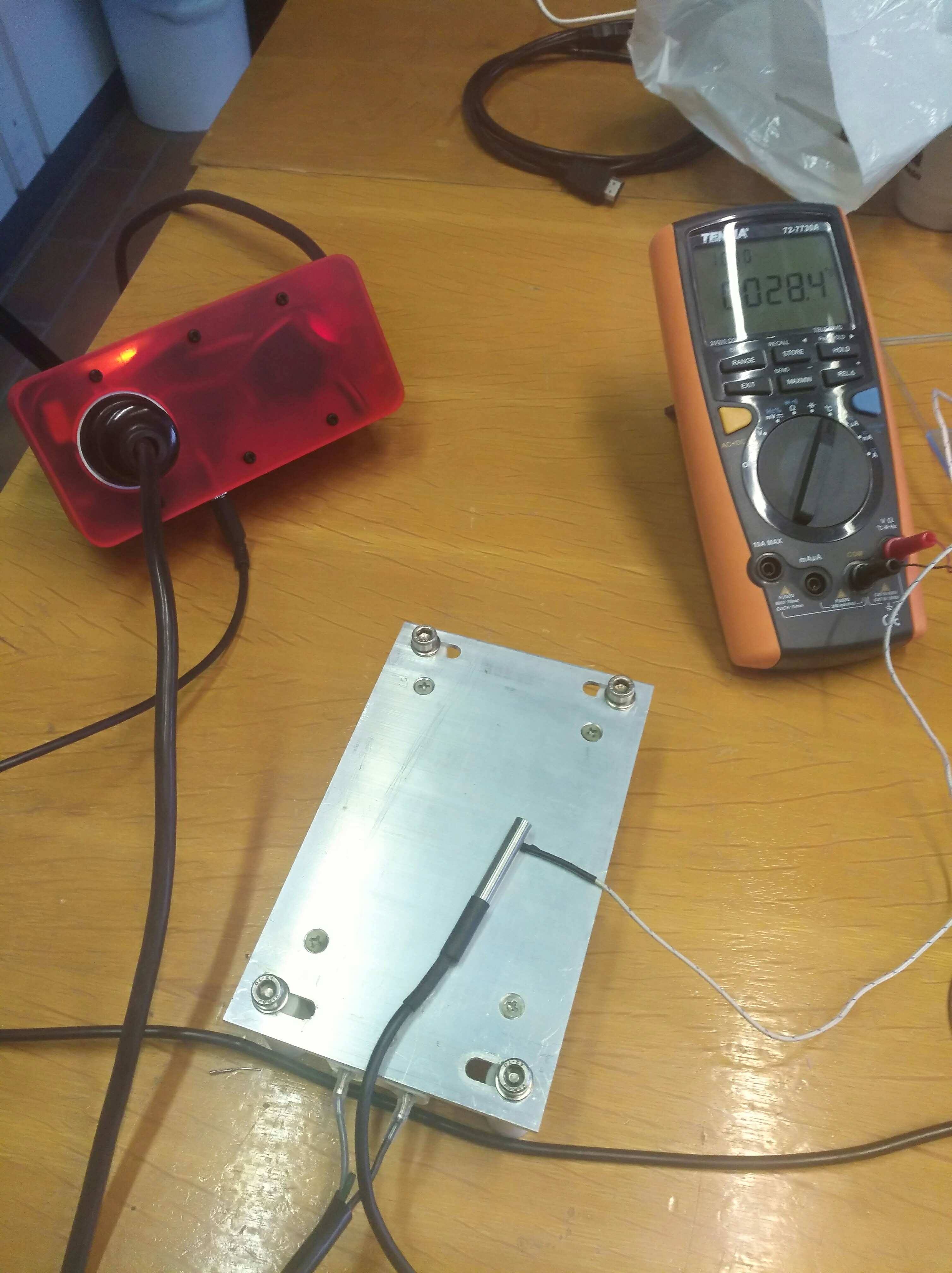
- Measure the temperature with a waterproof sensor
- Adjust a temperature set
- Adjust a set time to maintain this temperature
- Control 220V current circuit to plug the immersion heater, rice cooker or an electric hob.
- Maintain the set temperature for the set period of time.
- Notify when it's done
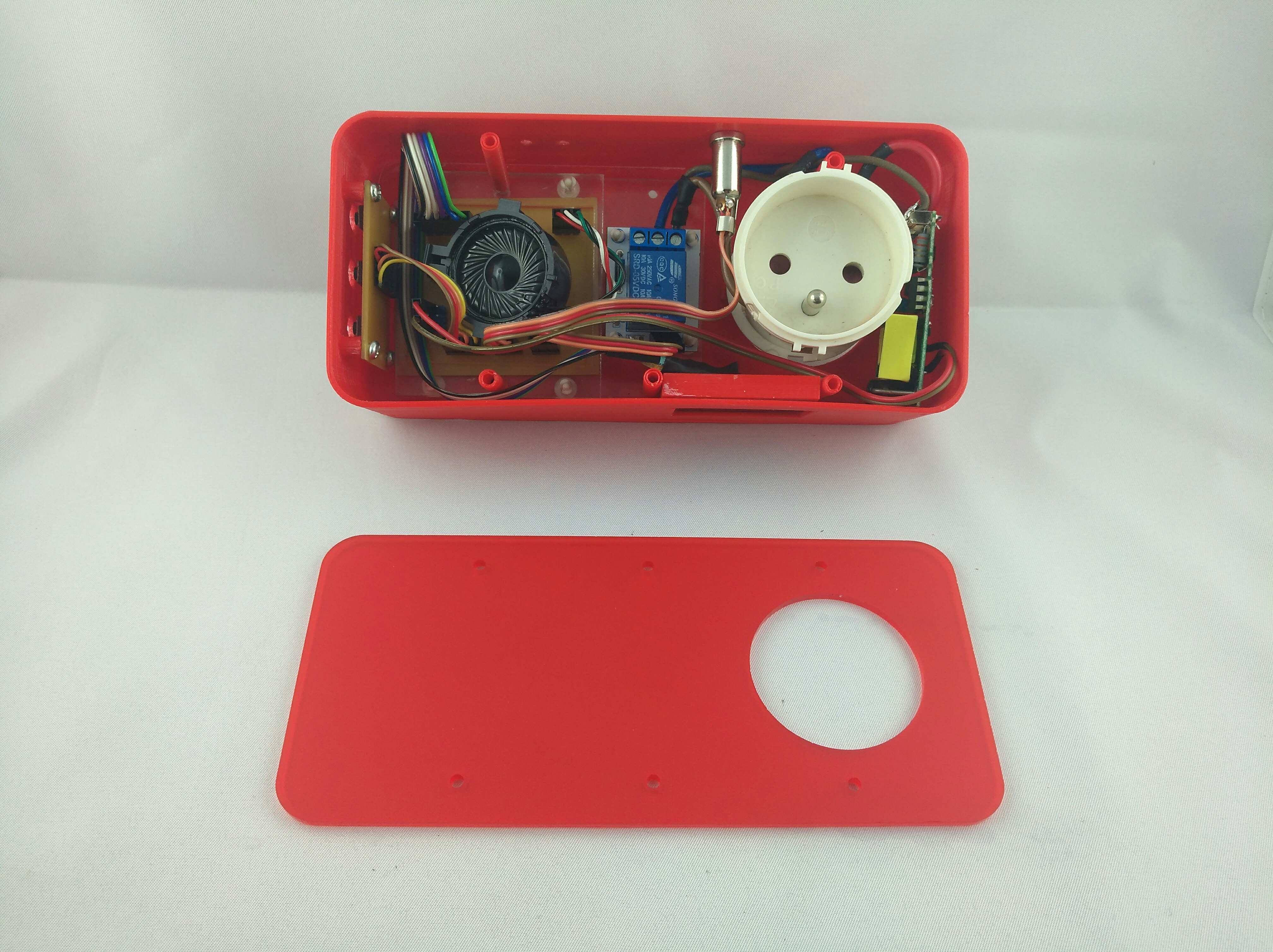
- A waterproof temperature sensor DS 18b20
- A relay 5V SRD 05V
- An I2C screen
- A speaker
- 3 buttons
- A transformer 220V to 5V
The full Bill of material is located in (week 18)
THE MICROCONTROLLER BOARD
To draw and make the manufacturing files,
I used KiCad, a software that I had already tested in week 5 and week 7 this year.
To make the electronic circuit, it is necessary to start by making a schematic.
This is where you set up the various components and their connections.
I opened the schematic on kiCad selected the components I need for the board,
connected the components to each other and to the microcontroller
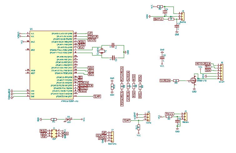
When done, a KiCad function allows you to number the different components
Then I associated the schematic components with the pcb footprint,
This is an important step that associates the component symbol with its physical footprint
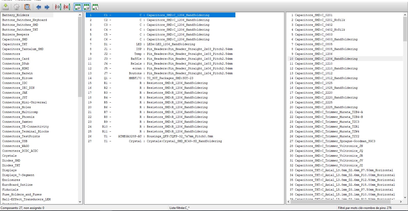
Finally I generated the Netlist.
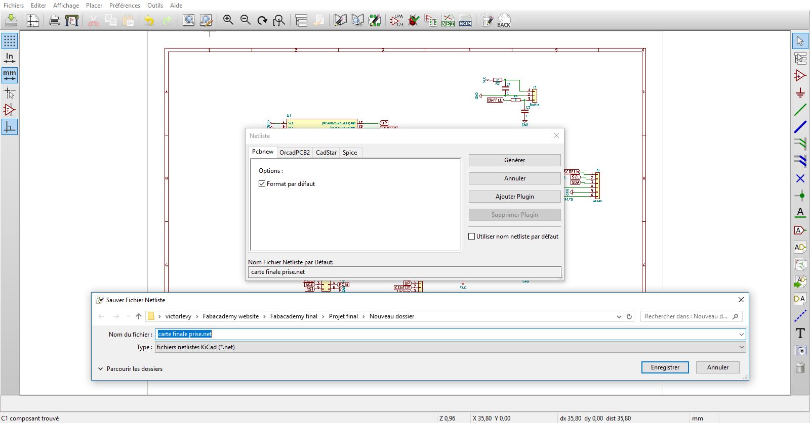
After I opened the window with the plane of the electronic circuit, the pcb plan.
I generated the Netlist.
The footprint are all superimposed with their respective connections.
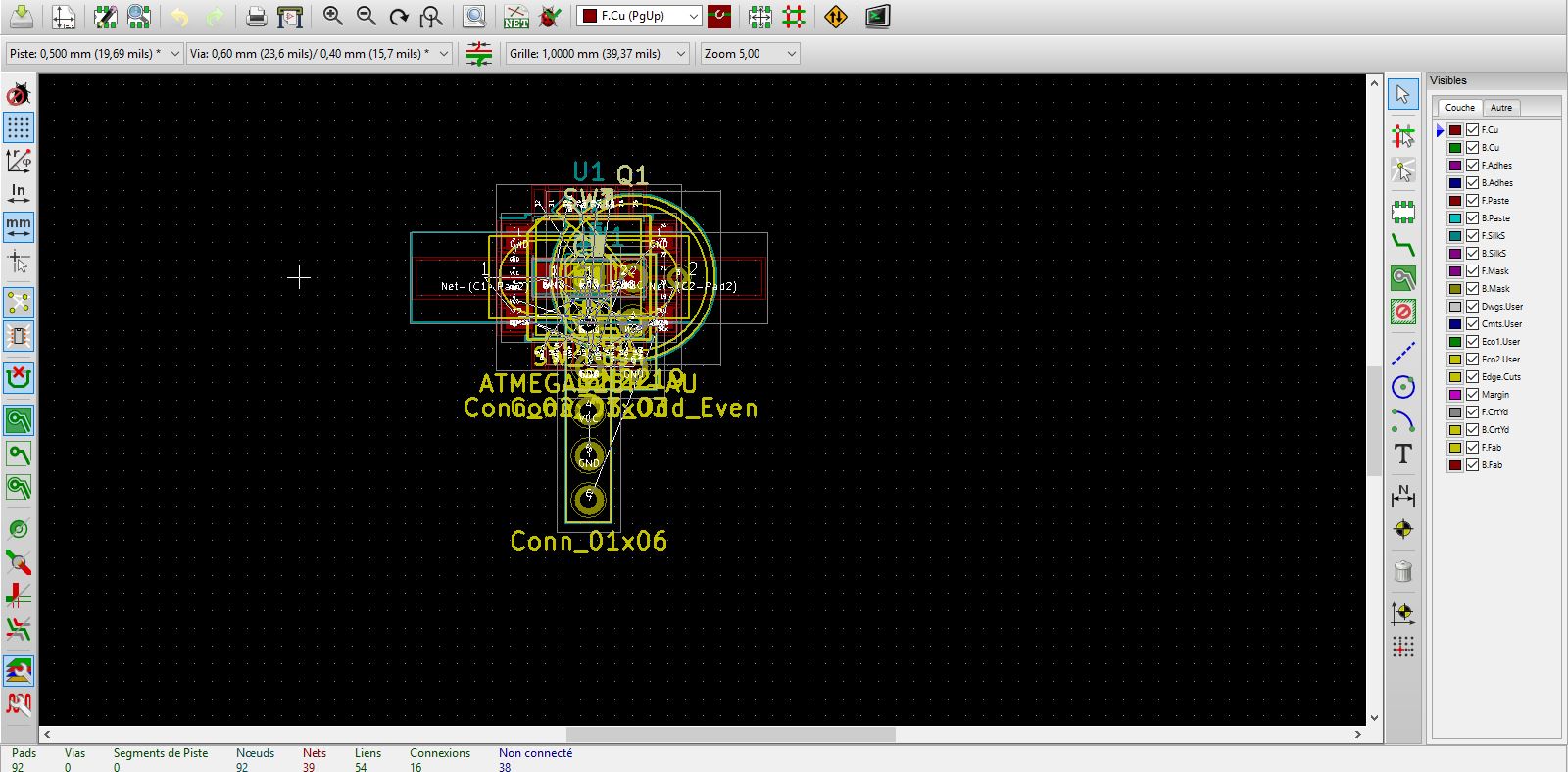
I placed the components taking into account their connection with the microcontroller.
And finally I connected with the paths the components between them and the components with the microcontroller.
It took me a long time because I wanted to avoid the jumper ...
I had to redo the drawing of the PCB because I was wrong in the order of connections of the ISP.
This forced me to add some 0 ohms resistors that served as a bridge between inaccessible connection locations.
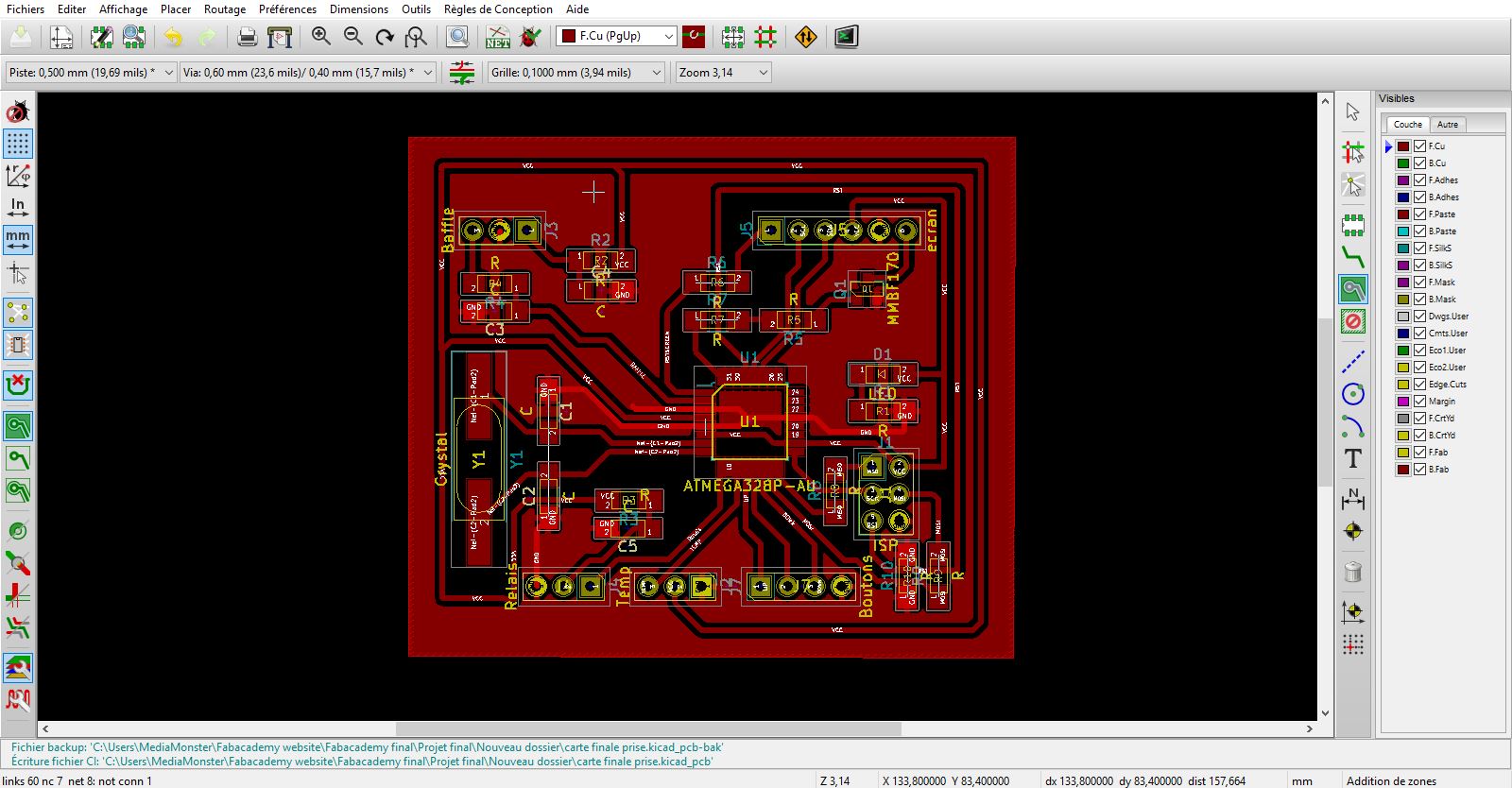
To do this, you have to go back to the diagram, and redo the whole procedure:
Add components, renumber, associate to fingerprints, create netlist and reconnect paths on PCB.
I also worked with a ground plane that connects all parts of the board to the ground.
A jumper was also needed to connect the reset paths to each other.
Once the pcb plan is completed, it must be exported to SVG file to be able to reverse it.
What it takes to engrave the paths on the pcb is the opposite of what KiCad generates.
What we need to have for the CNC is the plan of insulation between paths.
That's what you need to engrave to isolate the paths between them
The saved SVG must be imported into gimp.
After that I select the correct size of the circuit and export it in PNG.
I open it on Inkscape and transform it into vector.
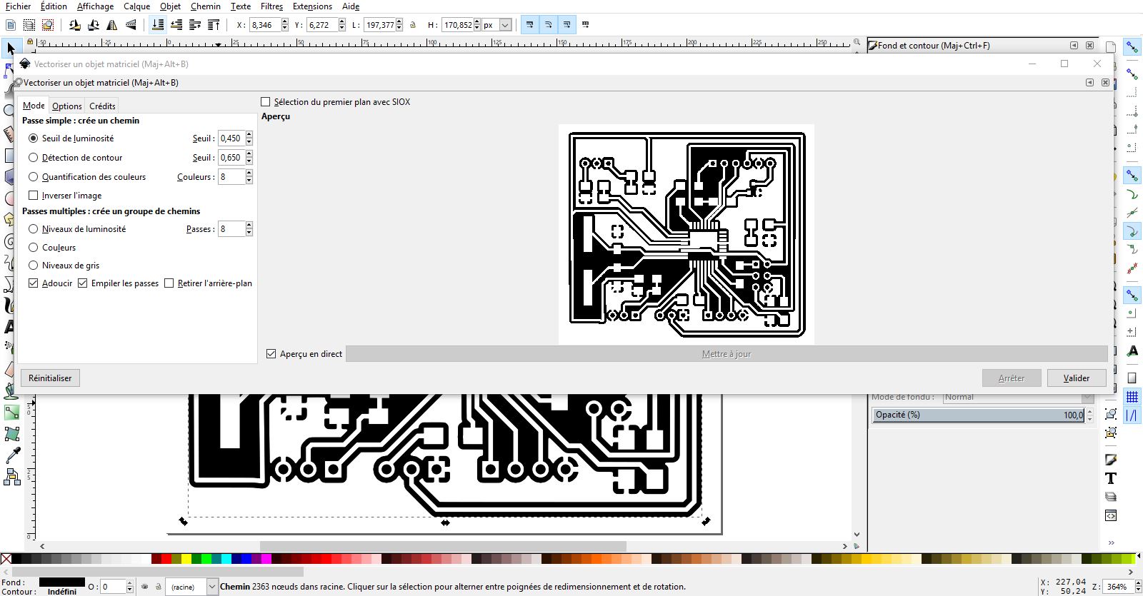
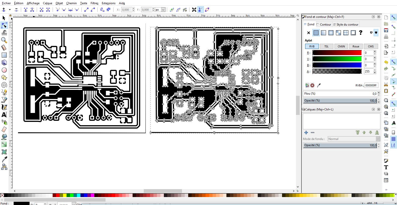
Export it in SVG, it is the format readable on Easel. I imported SVG into Easel, the software for our CNC machine
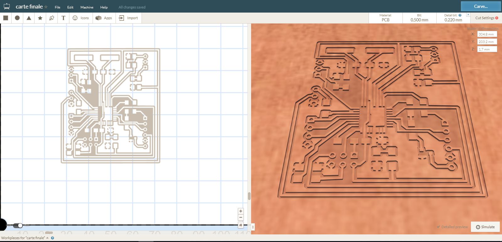
To engrave the electronic board, it is better to work in several passes:
rough passes, detailed passes and holes.
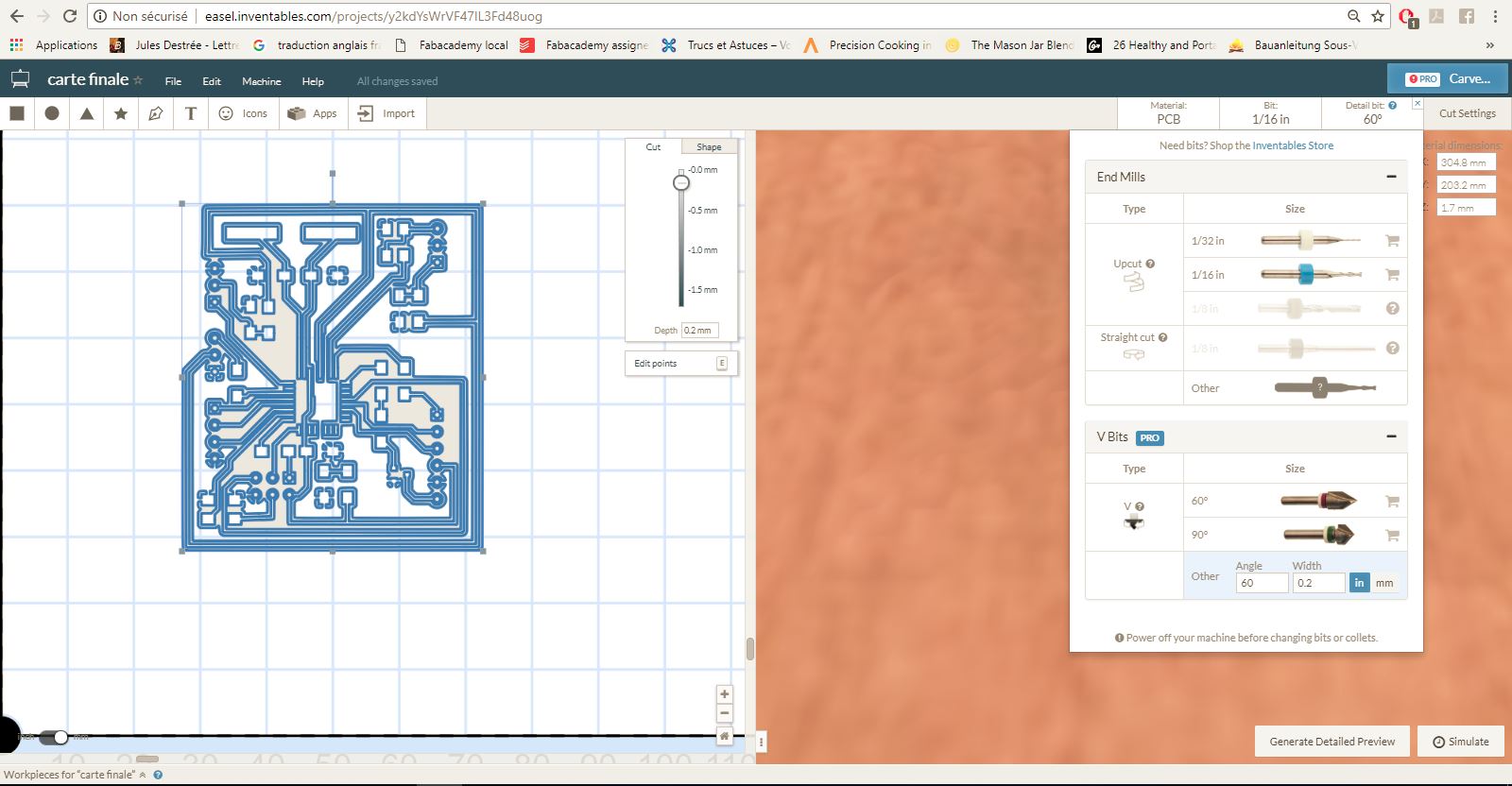
To make holes for the pinhead, I used a 8 mm bit
The first test was conclusive, except that the paths were too narrow ...
They have disassociated themselves from the resin.
I went back to KiCad to change the thickness of the paths in 0.4 mm.
I changed the design rules of the default paths in the program and then changed the thickness of the paths one after the other.
Then I did the whole the whole process again to make a second board : KiCad, Inkskape, Easel and making on the CNC machine.
When that done,we worked with Axel on the preparation of the components before mounting on the board.
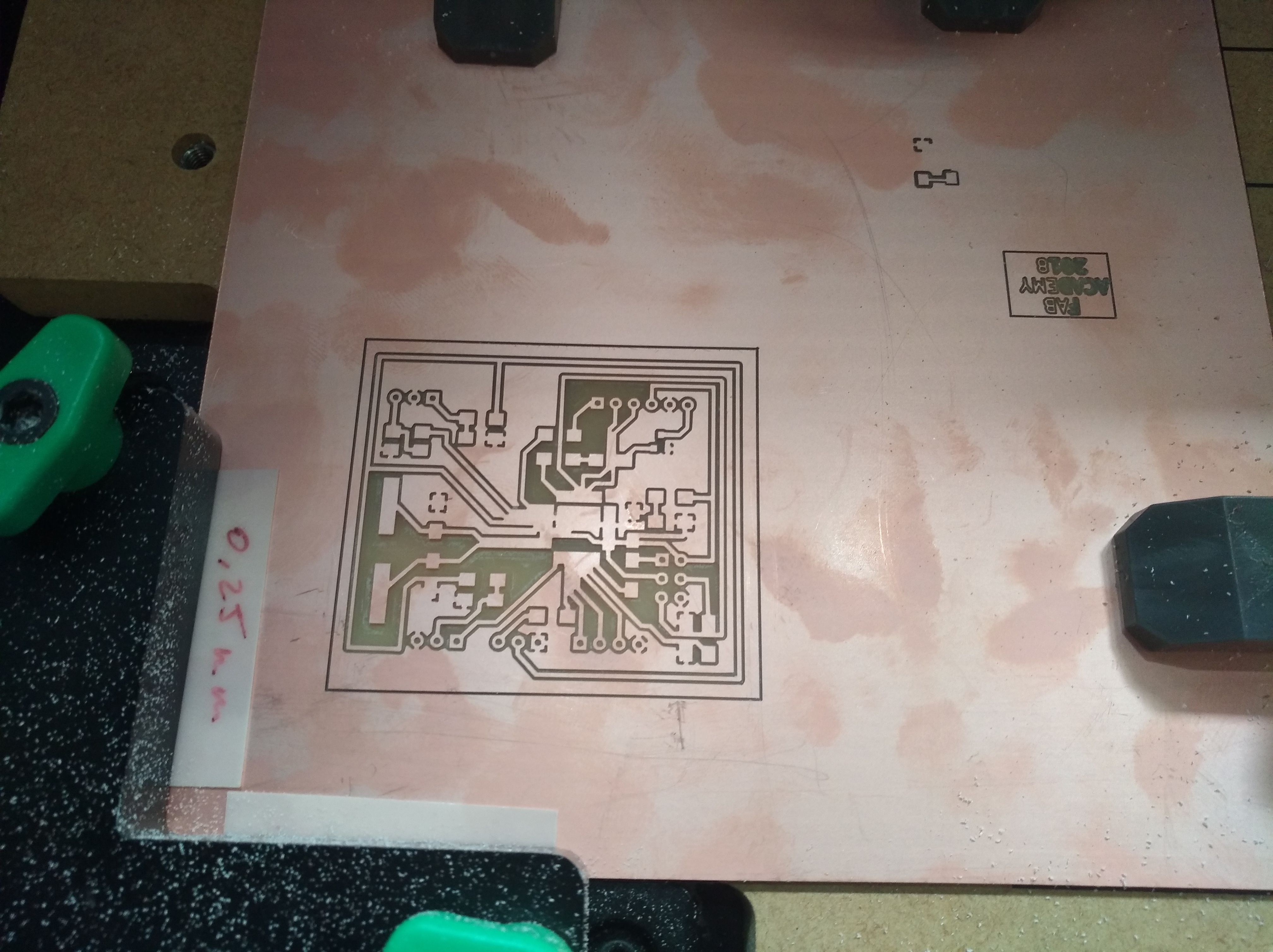
And there we are ...
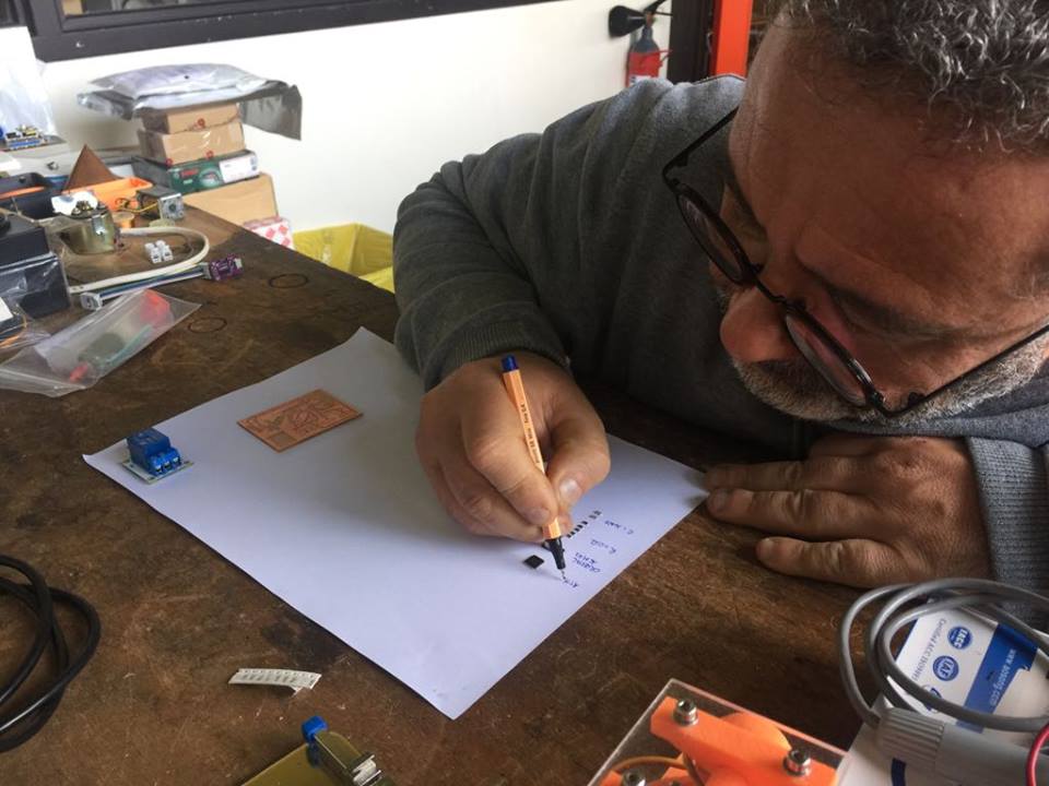
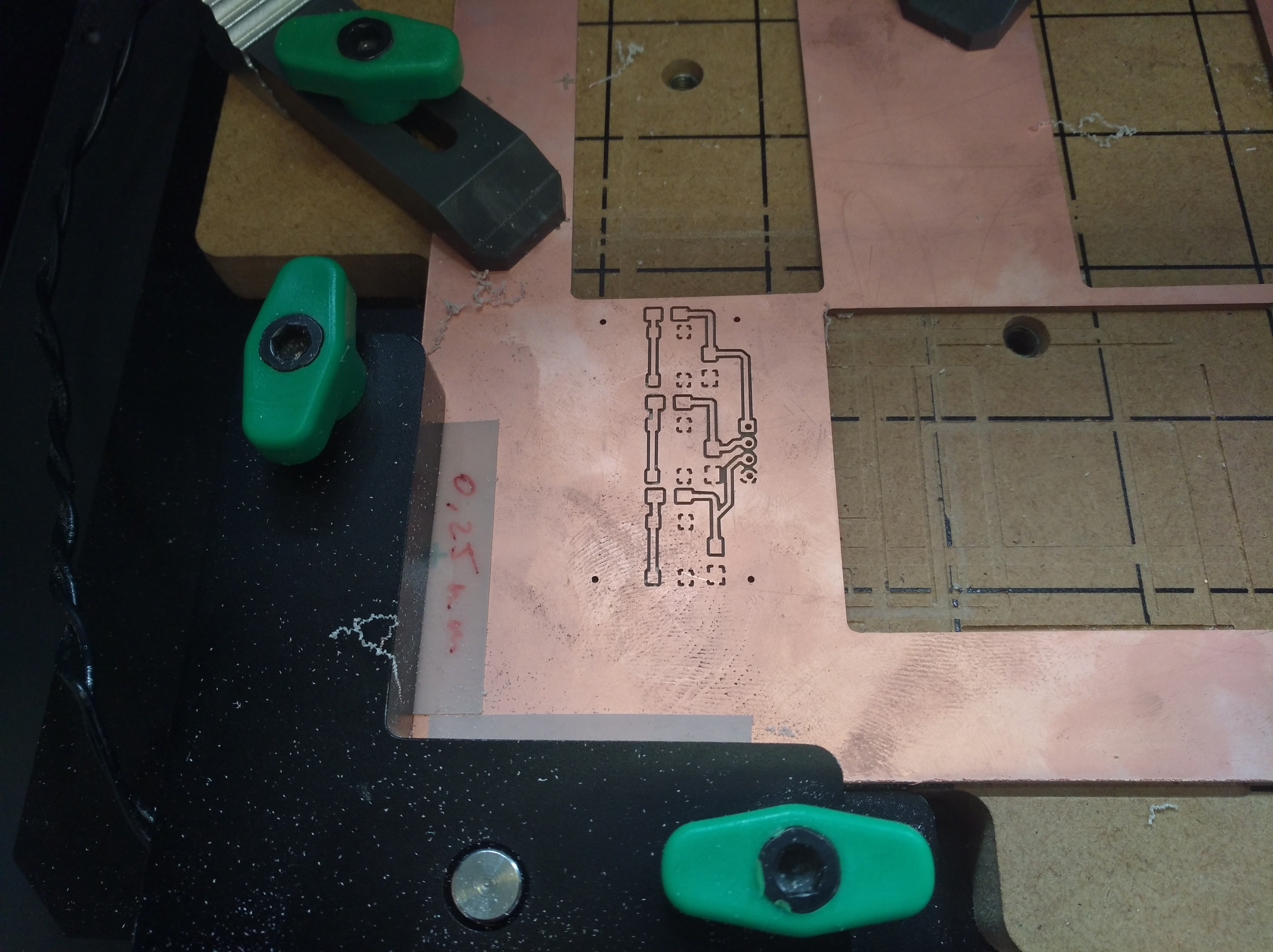
THE BUTTON BOARD
I used the same design process for the 3 buttons UP, CENTER, and DOWN.
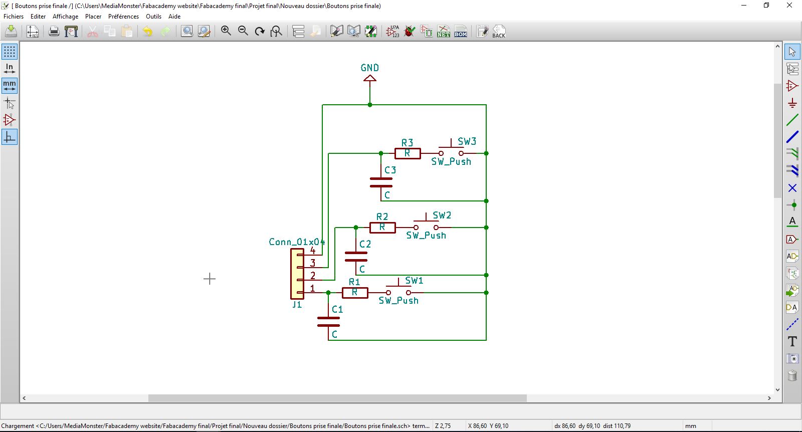
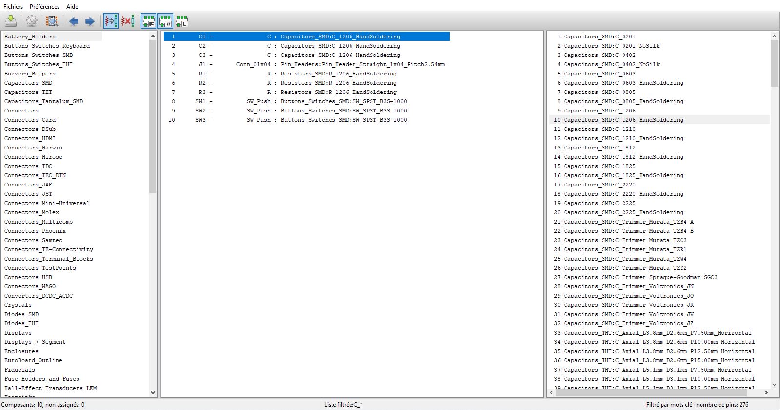
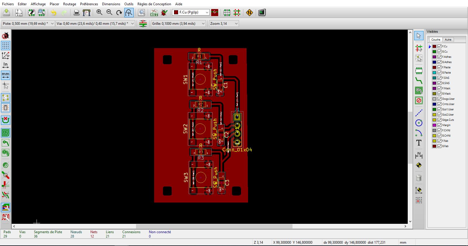
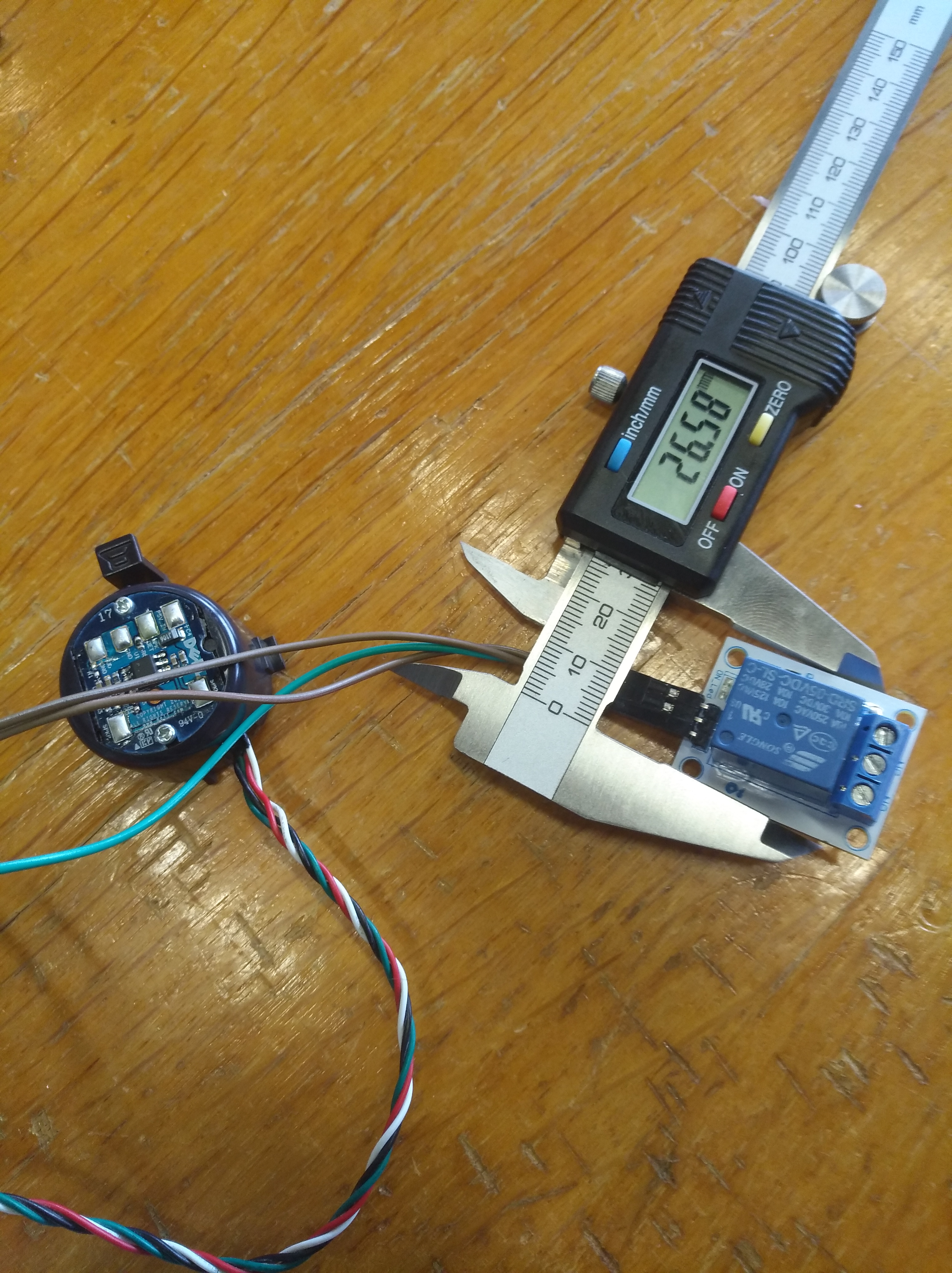
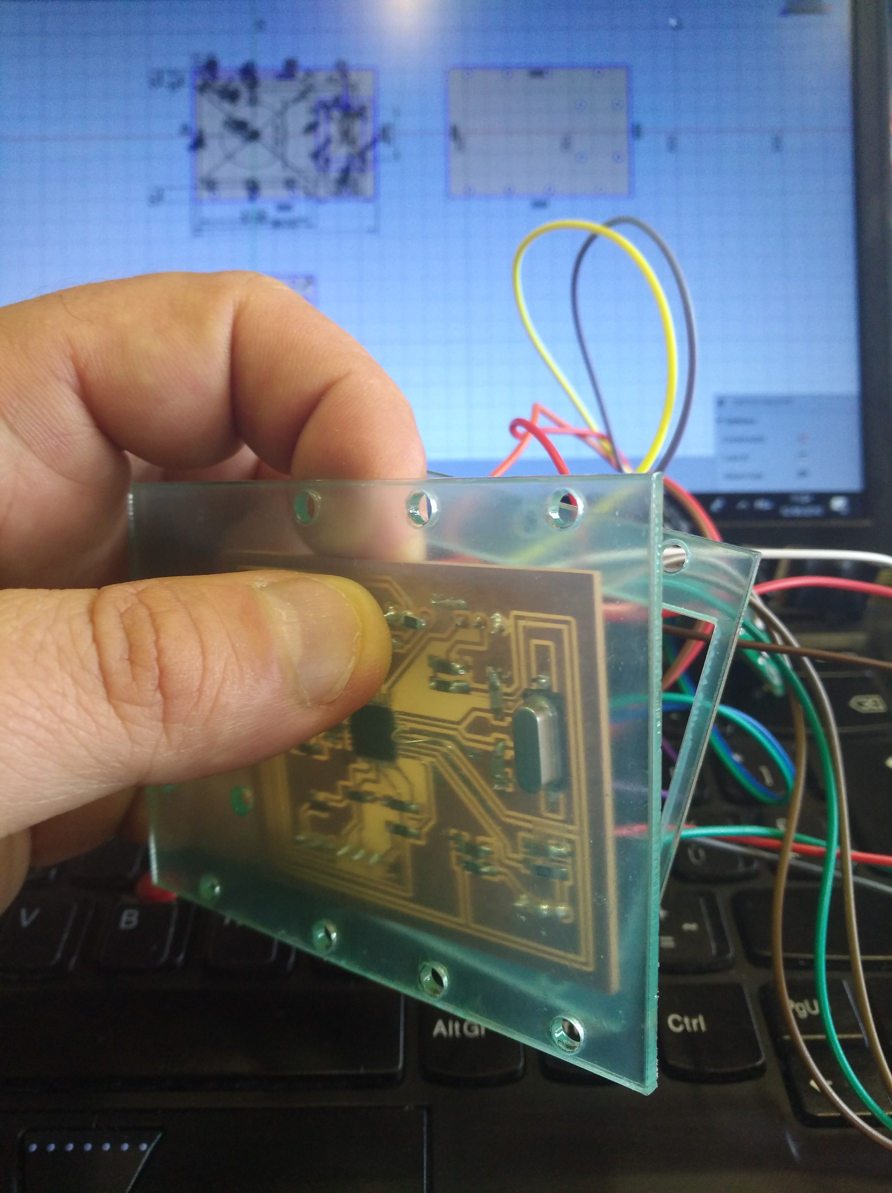
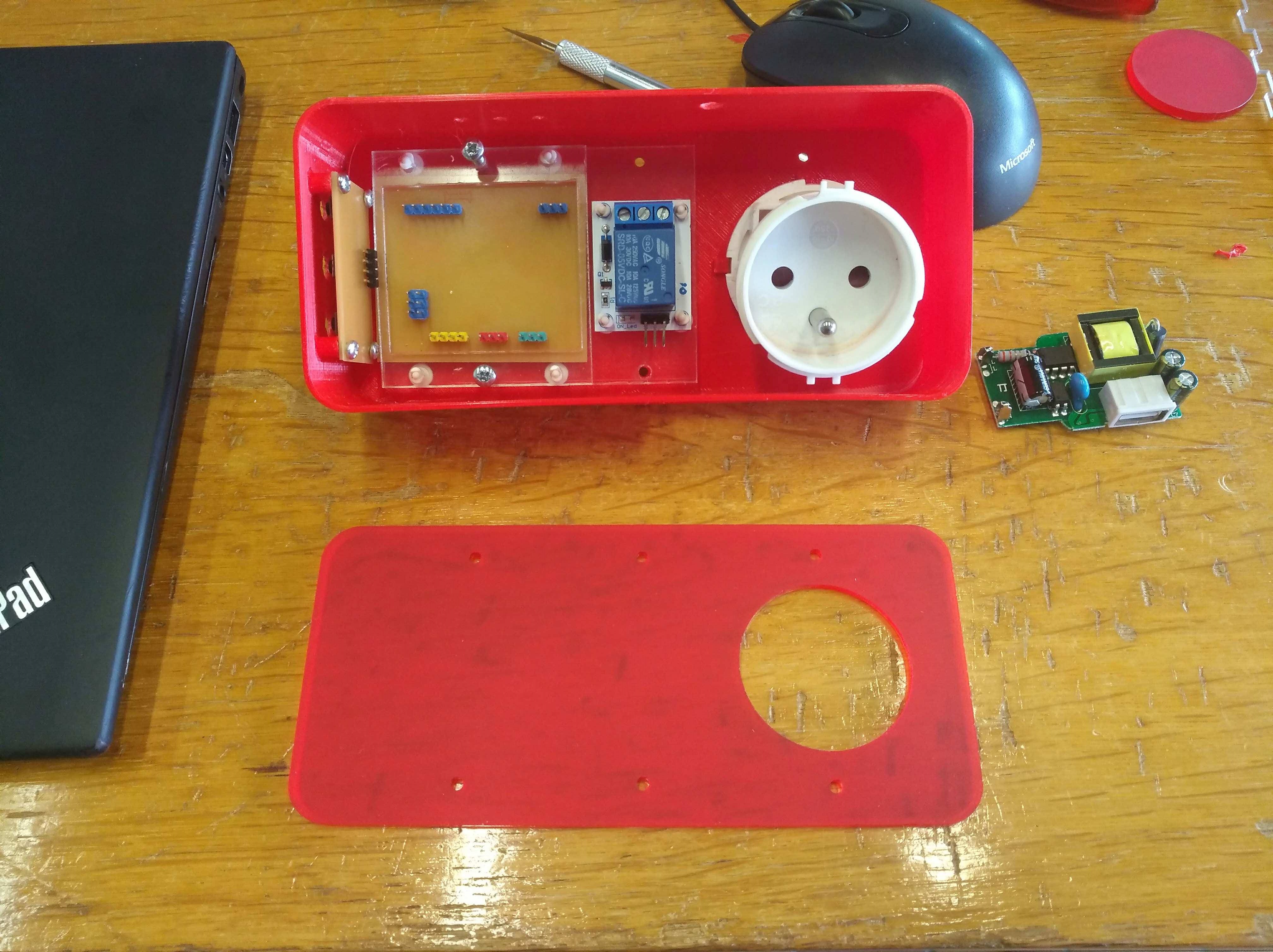
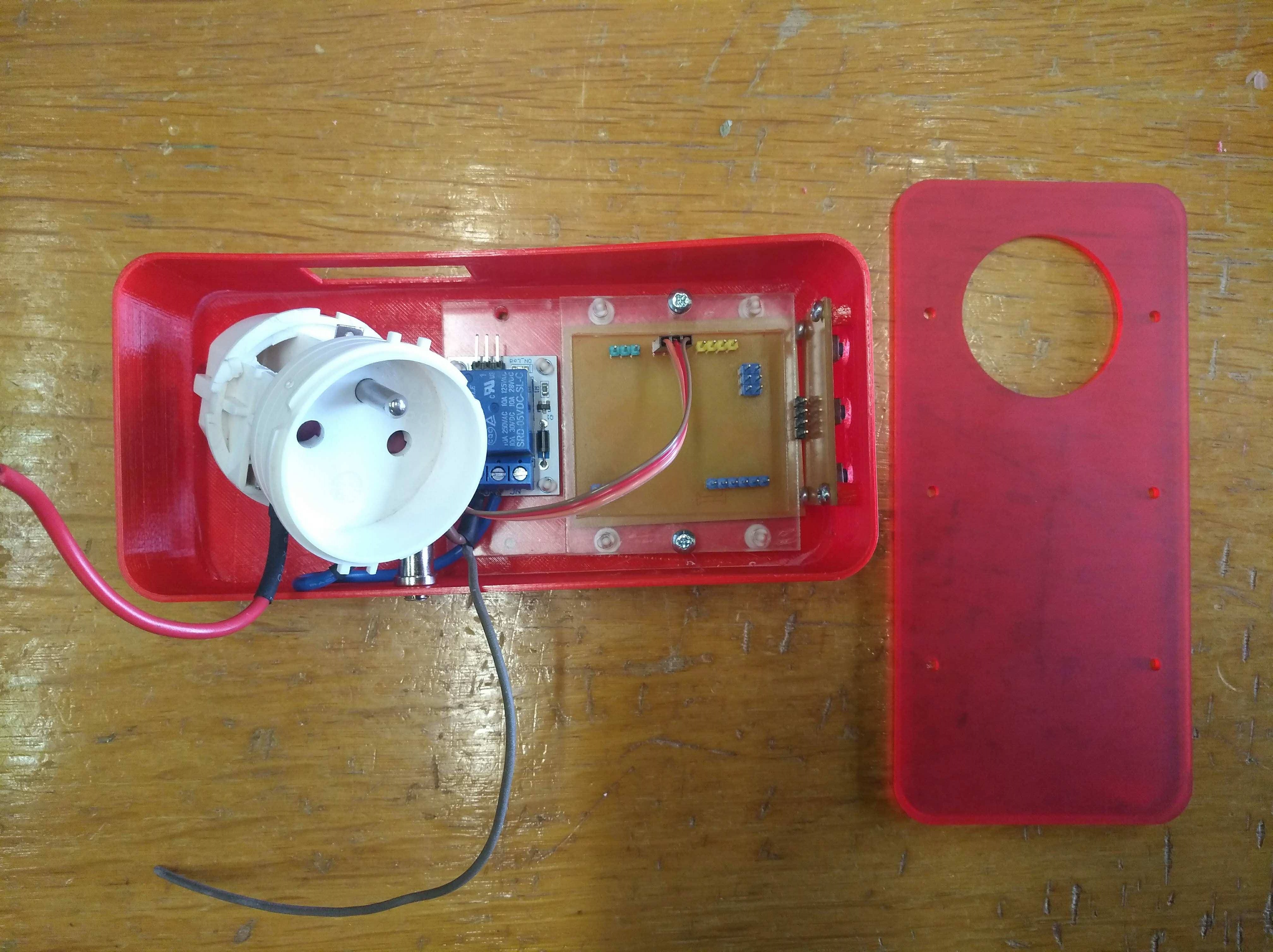
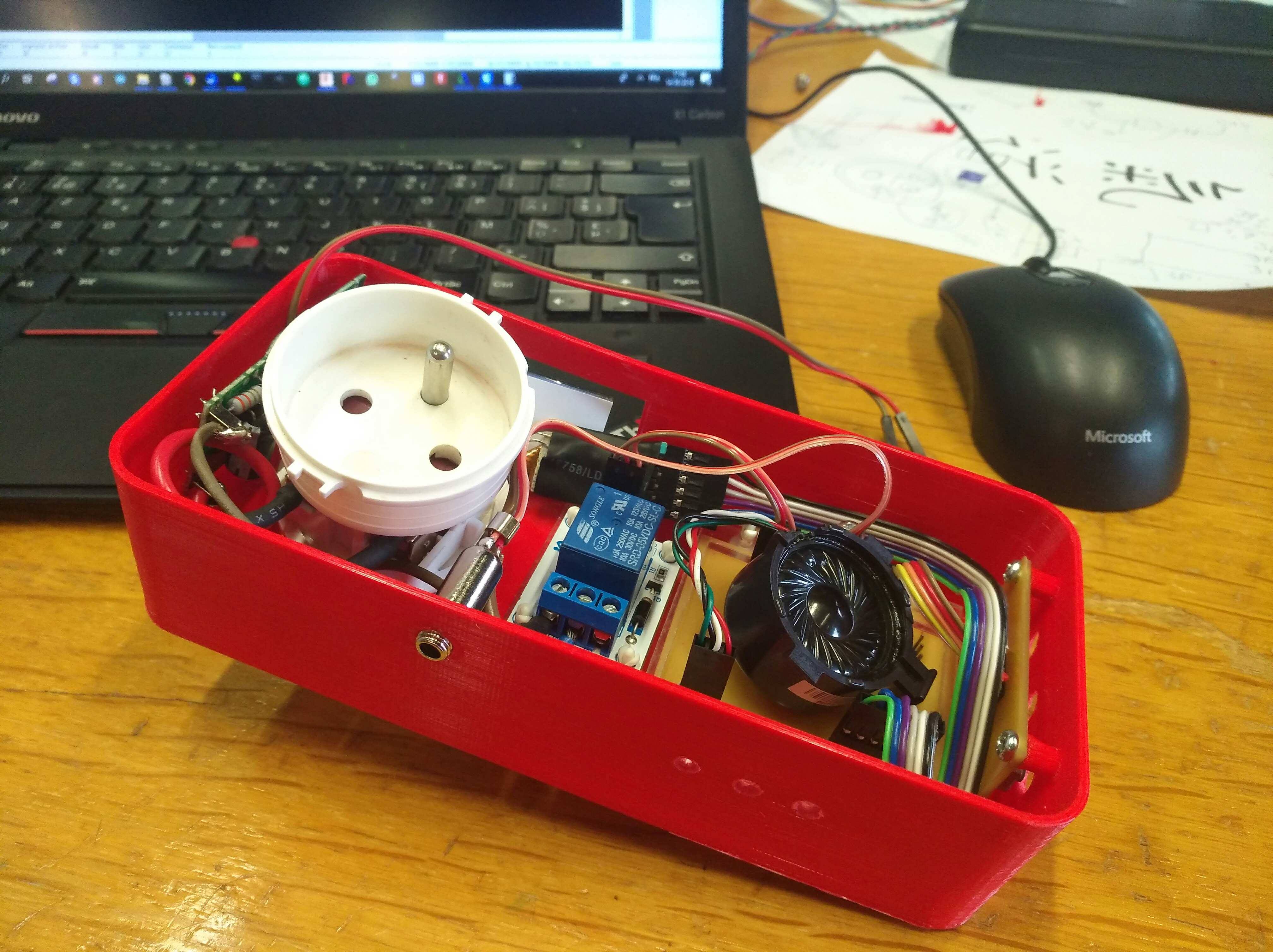
After that I measured the parts: Plug, relay, speaker, jack, screen.
I also lasercut some parts to check the dimensions of the button and plug.
DRAWING 2D, 3D
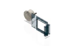
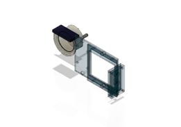
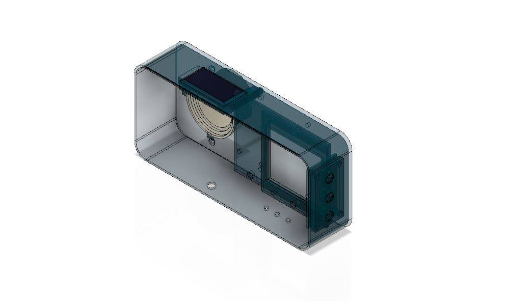
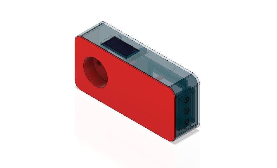
First I began with a sketch with the different parts.
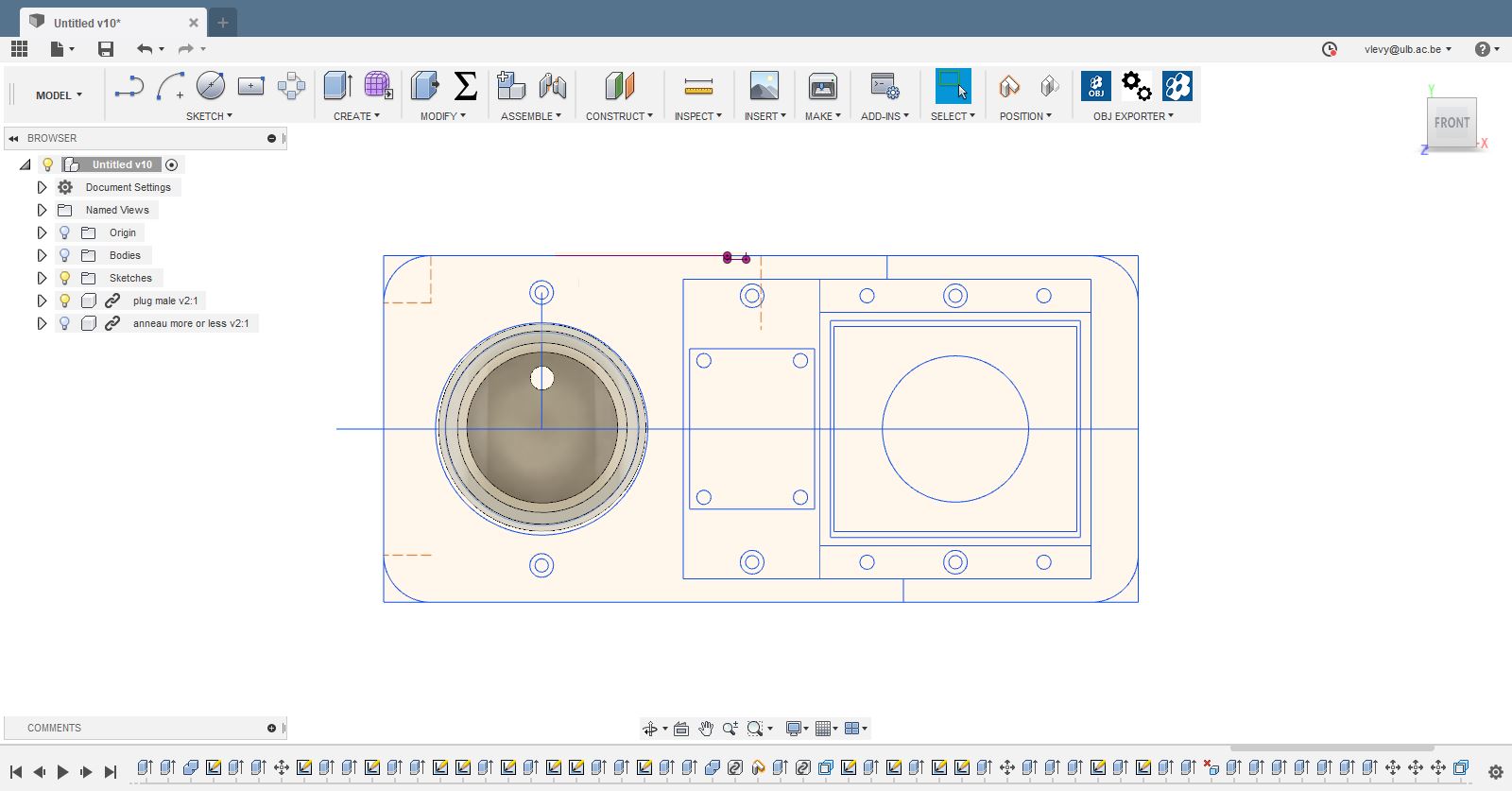
Then I draw them in 3D , see screenshot below .
"">
 =
=
"">
BURNING THE BOOTLOADER
After making the board, I loaded the boatloader using a usbtiny. For this I used the same procedure as in the week 9. I connected a usbtiny ISP programmer using the ISP connections: Miso,Mosi,GND,VCC,RST,SCK.
Opened Arduino IDE.
I selected the programmer: USBtinyISP.
Selected Arduino UNO as a board, my board is recognized thhat way.
And I chose: Burn bootloader(graver sequence d'initialisation in french ...).
From now I can use FTDI to program the board .
THE CODE
In this code, I will first, include the following libraries:
NewTone.h, OneWire.h, TimeLib.h, TimeAlarms.h, LCD_ST7032.h, "pitches.h"
I will use them because they have different functions to :
Generate sound,
Read the DB 18s20 temperature sensor
Read the hours, minutes, count down the time
Read the ST7032 LCD
Read a series of notes.
Then I will match the different components to the corresponding pins of the ATmega 328.
LCD reset (3), Led lcd (2), Speaker (4), Relay (5), DB 18s20 (7), Buttons up (8), Down (9), Center (10), ST7032 (lcd)
Give the starting values of the program to:
setting (0), set point (50), time (0) and minutes (0).
I will define the notes of the melody that will be played when the time is up,
thus their duration in the function melody and noteDuration.
In the Void Setup,
I will define how the different pins work:
OUTPUT or INPUT, and for the buttons using the internal pull-up resistor.
I will turn on the screen, determine its contrast, set the start cursor,
write the set temperature and the timer values that will count down the time every minute.
In the Void Loop:
I will first turn on the screen and write the different values: Set temperature, Hours, minutes.This will be activated when one of the buttons is pressed.
After, the code is written to allow to regulate the temperature with the buttons UP and DOWN,
to pass to the hours by pressing the CENTER button, to adjust with UP and DOWN to pass to the minutes and to adjust with the buttons UP and DOWN.
Then, by pressing CENTER, the timer will trigger.
At the end of the void loop, we will find the part of the code that will read the temperature of the sensor
CODE

/*

  inspired by the work of Muzi on Hackaday
  https://hackaday.io/project/26309-how-to-make-an-office-thermometer
  Modified by Victor Levy on the 15/06/2018 Fabacademy 2018

*/

#include NewTone.h>
#include OneWire.h>
#include TimeLib.h>
#include TimeAlarms.h>
#include LCD_ST7032.h>
#include "pitches.h"

#define lcd_rst 3
#define lcd_led 2
#define speaker 4
#define relay 5
#define thermo 7
#define up 8
#define down 9
#define center 10

OneWire ds(thermo);
LCD_ST7032 lcd;

String inString = "";
boolean arret = true;
int reglage = 0;
int consigne = 50;
int heure = 0;
int minutes = 0;


// notes in the melody:
int melody[] = { NOTE_C4, NOTE_G3, NOTE_G3, NOTE_A3, NOTE_G3, 0, NOTE_B3, NOTE_C4 };

// note durations: 4 = quarter note, 8 = eighth note, etc.:
int noteDurations[] = { 4, 8, 8, 4, 4, 4, 4, 4 };

void setup() {
  pinMode(up, INPUT_PULLUP);
  pinMode(down, INPUT_PULLUP);
  pinMode(center, INPUT_PULLUP);
  pinMode (relay, OUTPUT);
  pinMode(lcd_rst, OUTPUT);
  pinMode(lcd_led, OUTPUT);


  digitalWrite(lcd_rst, LOW);
  delay(50);
  digitalWrite(lcd_rst, HIGH);
  digitalWrite(lcd_led, HIGH);
  lcd.begin();
  lcd.setcontrast(25);
  lcd.setCursor(0, 1);
  lcd.write('T');
  lcd.print(consigne);
  lcd.write(' ');
  lcd.write(0xdf);
  lcd.write('C');
  lcd.setCursor(0, 0);
  lcd.write(0b111110);
  lcd.setCursor(1, 1);
  lcd.print("H");
   Alarm.timerRepeat(1, Repeats);

void loop() {

  Alarm.delay(10);

if (arret==true)
  {
    lcd.setCursor(0, 2);
    lcd.print(consigne);
    lcd.write(' ');
    lcd.setCursor(1, 2);
    lcd.print (zero(heure));
    lcd.write (':');
    lcd.print (zero(minutes));

    if ( not digitalRead (up))
    {
      switch (reglage) {
        case 0: consigne ++;
          break;
        case 1: heure ++;
          break;
        case 2: minutes += 1;
          if (minutes > 60) {
            minutes = 60;

          }
          break;
      }
      Alarm.delay(200);
    }

    if ( not digitalRead (center))
    {
      reglage ++;

      if (reglage <= 2) {
        switch (reglage) {
          case 0: lcd.setCursor(0, 0);
            lcd.write(0b111110);
            lcd.setCursor(1, 7);
            lcd.write(' ');
            break;
          case 1: lcd.setCursor(1, 0);
            lcd.write(0b111110);
            lcd.setCursor(0, 0);
            lcd.write(' ');
            break;
          case 2: lcd.setCursor(1, 7);
            lcd.write(0b111100);
            lcd.setCursor(1, 0);
            lcd.write(' ');
            break;
        }
      }
      else {
        arret = false;
      setTime(0, 0, 0, 1, 1, 1); // date 0 h 0 min 59 sec 1 janvier 2001
    // Repeats();

        reglage = 0;
        lcd.setCursor(1, 7);
        lcd.write(' ');
      }
      Alarm.delay(400);
    }

    if ( not digitalRead (down)) // on a appuyé sur -
    {
      switch (reglage) {
        case 0: consigne --;
          if (consigne < 30) {
            consigne = 30;
          }
          break;
        case 1: heure --;
          if (heure < 0) {
            heure = 0;
          }
          break;
        case 2: minutes -= 5;
          if (minutes < 0) {
            minutes = 0;
          }
          break;
      }
      Alarm.delay(200);
    }
  }
  else // (arret == false) // si la variable arret = 0, le chronometre tourne
  {
    float temperature = getTemp();
    if (temperature < consigne)
    {
      digitalWrite(relay, HIGH);
    }
    else
    {
      digitalWrite(relay, LOW);
    }

    if ( not digitalRead (center)) {
      arret = true;
      Alarm.disable(0);
      digitalWrite(relay, LOW);
      reglage = 0;
      lcd.setCursor(0, 0);
      lcd.write(0b111110);
      Alarm.delay(400);
    }
  }
}


void Repeats() {
  if(arret==false){

  int difmin = minutes - minute();
  int difheure = heure - hour();
 if (difmin > 0 or difheure > 0 or second()>0)
  {
    lcd.setCursor(1, 2);
    lcd.print(zero(difheure));
    lcd.write(':');
    lcd.print(zero(difmin));
    lcd.write(' ');
  }

  else
  {

    digitalWrite(relay, LOW);


    for (int thisNote = 0; thisNote < 8; thisNote++) { // Loop through the notes in the array.
      int noteDuration = 1000 / noteDurations[thisNote];
      NewTone(speaker, melody[thisNote], noteDuration); // Play thisNote for noteDuration.
      delay(noteDuration * 4 / 3); // Wait while the tone plays in the background, plus another 33% delay between notes.
    }
    lcd.setCursor(0, 0);
      lcd.write(0b111110);
      arret = true;
  }
}
}

float getTemp() {
  //returns the temperature from one DS18S20 in DEG Celsius

  byte data[12];
  byte addr[8];

  if ( !ds.search(addr)) {
    //no more sensors on chain, reset search
    ds.reset_search();
    return -1000;
  }

  if ( OneWire::crc8( addr, 7) != addr[7]) {
    Serial.println("CRC is not valid!");
    return -1000;
  }

  if ( addr[0] != 0x10 && addr[0] != 0x28) {
    Serial.print("Device is not recognized");
    return -1000;
  }

  ds.reset();
  ds.select(addr);
  ds.write(0x44, 1); // start conversion, with parasite power on at the end

  byte present = ds.reset();
  ds.select(addr);
  ds.write(0xBE); // Read Scratchpad


  for (int i = 0; i < 9; i++) { // we need 9 bytes
    data[i] = ds.read();
  }

  ds.reset_search();

  byte MSB = data[1];
  byte LSB = data[0];

  float tempRead = ((MSB << 8) | LSB); //using two's compliment
  float TemperatureSum = tempRead / 16;

  return TemperatureSum;

  static int counter = 0;


}

String zero(int nombre)
{
  String texte = "";
  if (nombre < 10) {
    texte = String(0) + String(nombre);
  }
  else {
    texte = String(nombre);
  }
  return texte;
}
A SUMMARY OF THE DIFFERENT STEPSFirst step: coding with my Sashakit:
- Test the circuit with a universal board and the input and output devices
- Write the code in several steps:
testing the screen, temperature reading, timer reading, timer accuracy test, button interface, - Measure consumption of the circuit to choose a 5 V transfomer
Second step:drawing the board and the buttons
- Draw the microcontroller board in function of the necessary pin used
Third step: Making the board and buttons
- Manufacture the microcontroller board
- solder the component
- Test with ohmeter
- Rectification
- bootloader
- Manufacture the button board
- Manufacture the Pcb
- solder the component
- Test
Forth step: Mesuring the parts
- Measure the parts: Plug, relay, speaker, jack, screen
Fifth step: 2D, 3D drawing
- 2D draw
- Basic plan organization of elements
- 3 d model
- Drawing the plan of the different parts
- Mounting the base board
- Verification
- Temporary wiring
- Test
- Custom wiring and soldering
- Test
- And finally soup making...!
Here is a link to my final project page
HOME FINAL PROJECT