Embeded programming
Week 9
ASSIGNMENT- Read a microcontroller data sheet.
- Program your board to do something
- with as many different programming languages and programming environments as possible.
SOFTWARE USED
- KiCad
- Arduino IDE
FILES
Home made satshakit KiCad
Bouton Led
Fade 2 Led
GROUP ASSIGNMENT
testing electronic group page
LEARNING EXPERIENCE
This week was very interesting in what I learned , how I learned it.
I read the Atmega 328 datasheet and tried to understand it
Impossible alone without better explainations
I am a complete beginner in electronic and programming, I decided to work with 2 students/tutors.
Thomas and Quentin are both in the last year of engineering faculty.
One in mecatronic,the other in electronic design
It was a kind of beta testing for what we want to do for next year
The idea is to have students in final year tutoring the fabacademy students on each assignments
I learned the basics necessary to approach the way a microcontroller works
Very good experience to be student of 2 students
READING A MICROCONTROLLER DATASHEET
First thing to understand is that each pin of a microcontroller can have different fonctions
This can be read in the PIN CONFIGURATIONS wich shows the pin out of the microcontroller
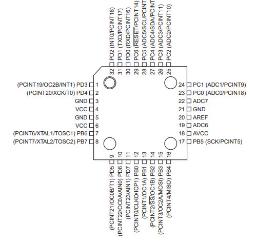
Pin functions
VCC GND
5V,ground
MISO MOSI SCK RESET
SPI protocol
SCL SDA
I2C protocol
XTAL1 and XTAL 2
external clock
ADC
analog to digital
PCINT
interrupt the microcontroler
PWM
analog modulation with digital input
RESET
Restart the micrcontroler
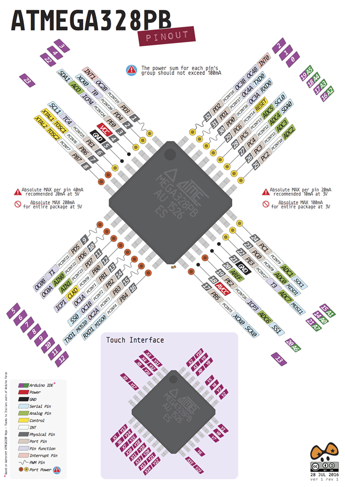
Pinout microcontroller vs Arduino
I also learned that if you wanted to program in Arduino IDE
Pin number of the microcontroller and the pin in Arduino IDE are different
For example: ADC 0 on the program is on pin 13 on the microcontroler
Here is a interresting pinout diagram of the ATMega 328 comming from pigixxx.
Lot's of tools in this website for electronic beginners...
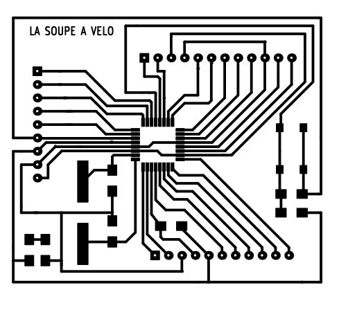
HOMEMADE SATSHAKIT
To do this exercise, I used a board inspired by the satshakit.
I looked at 2015 fabacademy archive to find some inspiration.
The satshakit project was made during Daniele Ingrassia's Fabacademy 2015.
I drew it and made it just before this session of the fabacademy,
I wanted to have a board equivalent to an arduino with all the pins connected with some special features:
I used Daniele satshakit as base and added:
- More VCC and GND than needed.This allowed me to avoid jumpers.
I used pinheader pins that are not directly related to the microcontroller but serve as a bridges.
- A pull up resistance of 4,7 kohms for a DS 18b20 temperature sensor that I use regularly.
- I2C connections with GND and VCC next to each other to plug a I2C screen easily.
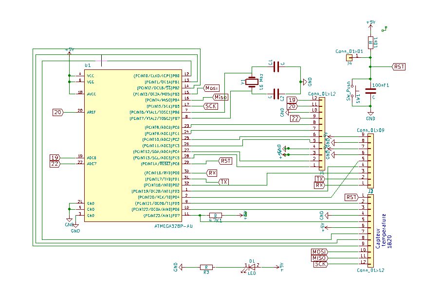
DRAWING OF THE SCHEMATIC ON KiCad
It always starts there ...
You have to place the microcontroller,an ATmega 328,
add the components you need ,
and then connect them in a schematic.
drawing
Then you have to follow a series of steps...
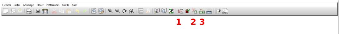
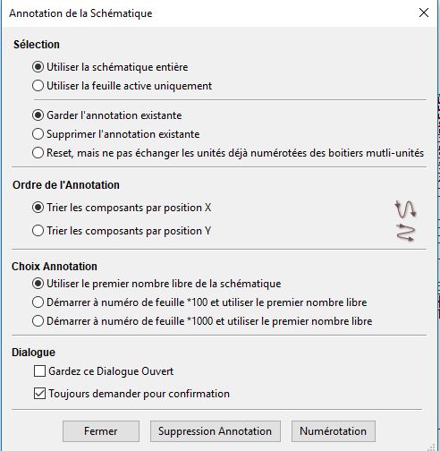
Step 1 :You have to number the components(1).
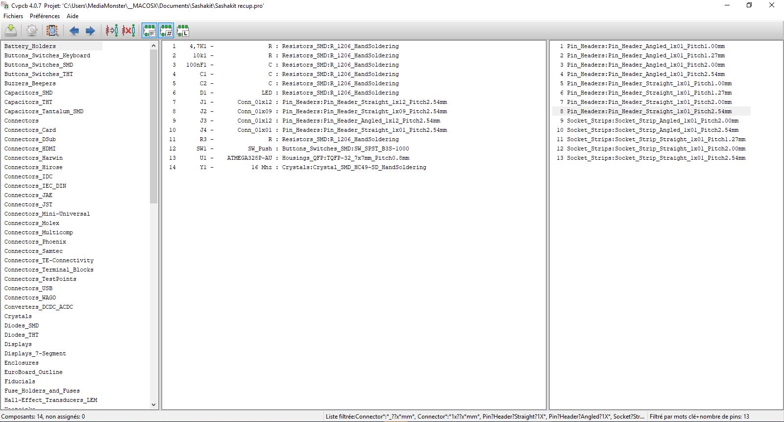
Step 2 :Once it's done, you have to associate the components and the footprints(2).
This step is not always easy, because not all components are included in the KiCad library.
What is important to understand is that we will associate a symbol,
a resistance for example and the size that this resistance takes on the board.
We do not speak of value that happens only at the time of the actual choice, at the time of the soldering.
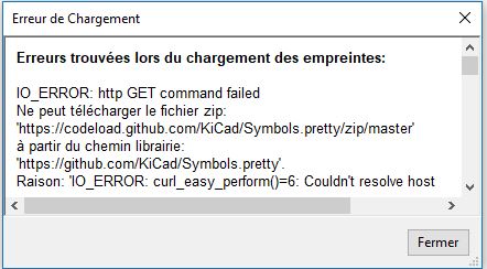
This message of error is a message I had.
It happens when you are not connected to the net.
Lot's of false information on forums ...
Step 3: Then, generate the NETLIST by clicking the NET icon(3).
This will save this list of components and their connections in a .Net file.
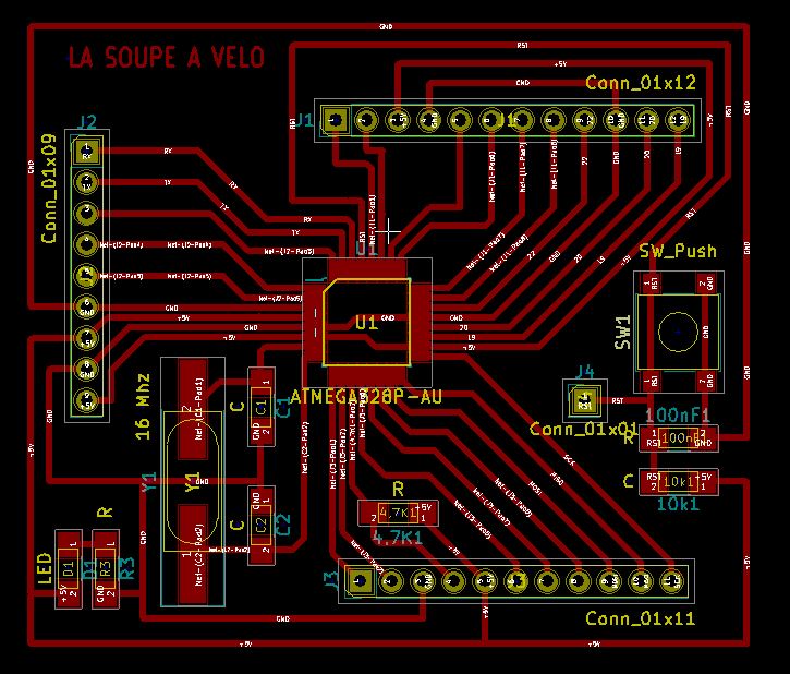
Then I opened the PCB file which is where we will put the elements in place and draw the board.
We will discover an apocalyptic vision: a drawing with superimposed components.
Step one, redistribute them by placing them in front of the pins or they must be connected.
It will be necessary to return them, to move them ...
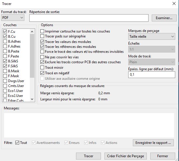
When it's done, you have to define the design rules: Path width, insulation ...
And then it remains only to connect the components with the tool that traces the path.
There is a round trip between schematic and PCB to add jumper or in this case modify the pinheader.
The procedure is as follows:
- Open .sch file
- modification schematic,
- numbering,(1)
- association components and footprints,(2)
- generate the Netlist,(3)
- reopen the file .pcb,
- read the Netlist and the changes appear in the drawing of the PCB.
To make the board, it was made at the same time as that of the week5, with the same process.
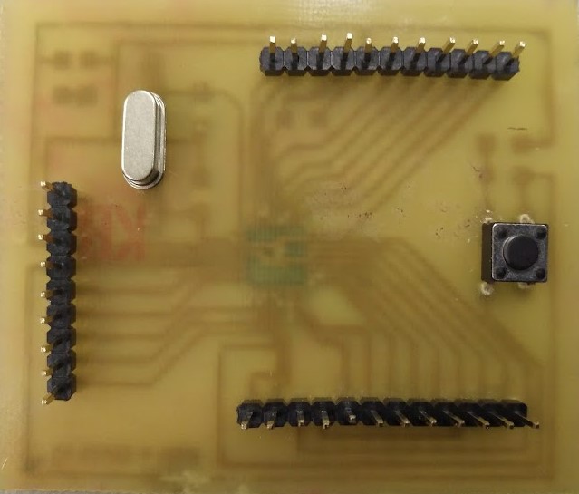
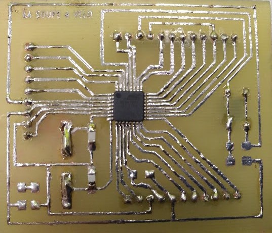
unfortunately, I forgot to put a capacitor on the reset, so I have to put it each time when using this board.
ARDUINO BOOTLOADER
I connected a usbtiny ISP programmer using the ISP connections: Miso,Mosi,GND,VCC,RST,SCK.
Opened Arduino IDE.
I selected the programmer: USBtinyISP.
Selected Arduino UNO as a board.
And I chose: Burn bootloader(graver sequence d'initialisation in french ...).
From now I can use FTDI to program the board and read the serial monitor.
ARDUINO IDE
I decided to start at an affordable level for myself.
I preferred to gain some confidence in an unknown and complex area.
This website is quite useful to test and understand basic examples with tutorials
I used an arduino Uno board to begin with,to concentrate on the programming part
First assignment was to make the internal led blink,using the blink example and replacing the led pin to 13 in the sketch
You must select the type of board in the tool menu
and load the sketch in the microcontroler
I also changed the delay function to make it blink longer: 5 seconds/5000 ms
                  Code

                  /*
                Blink

                Turns an LED on for one second, then off for one second, repeatedly.

                most Arduinos have an on-board LED you can control. On the UNO, MEGA and ZERO
                it is attached to digital pin 13, on MKR1000 on pin 6. LED_BUILTIN is set to
                the correct LED pin independent of which board is used.
                If you want to know what pin the on-board LED is connected to on your Arduino
                model, check the Technical Specs of your board at:
                https://www.arduino.cc/en/Main/Products

                modified 8 May 2014
                by Scott Fitzgerald
                modified 2 Sep 2016
                by Arturo Guadalupi
                modified 8 Sep 2016
                by Colby Newman

                This example code is in the public domain.

                http://www.arduino.cc/en/Tutorial/Blink
                    */

                  void setup() {

                    pinMode(13, OUTPUT);
                  }


                  void loop() {
                    digitalWrite(13, HIGH);
                    delay(5000);
                    digitalWrite(13, LOW);
                    delay(5000);
                  }
Then I decided to switch a led with a button
                  Code


                   /*

                    Victor Levy, Fabacademy 2018, week 9, embedded programming
                    Switching on and of a ler with a button

                    */


                  const int switchPin = 4;
                  const int ledPin = 8;
                  int switchState = 0;
                  void setup()
                  {
                  pinMode(ledPin, OUTPUT);
                  pinMode(switchPin, INPUT);
                }
                void loop()
                {
                  switchState = digitalRead(switchPin);
                  if (switchState == HIGH);
                  {
                    digitalWrite(ledPin, HIGH);
                    delay(3000);
                    digitalWrite(ledPin, LOW);
                  }
                }
Then I made a new test with 1 led to fade in/out
The first code was just made in copying the last part in the void loop
Then I wanted to make one led fade fade in/out
The fadeamount is increasing by 5
The sign of the fadeamount will change to go from 255 to 0 and from 0 to 255(see comment in the code)
And then I did a code for 2 led to fade in/out.
                Code


                /*

                Victor Levy, Fabacademy 2018, week 9, embedded programming
                Making 2 leds fade and out

                */


                int led = 9;
                int LED=10;
                int brightness = 0;
                int BRIGHTNESS = 255;
                int fadeAmount = 5;


                void setup() {

                  pinMode(led, OUTPUT);
                  pinMode(LED, OUTPUT);
                }


                void loop() {

                  analogWrite(led, brightness);


                  brightness = brightness + fadeAmount; // (ex 0+5+5...)


                  if (brightness <= 0 || brightness >= 255) {
                    fadeAmount = -fadeAmount;
                  }

                  delay(30);

                  analogWrite(LED, BRIGHTNESS);
                  BRIGHTNESS = BRIGHTNESS - fadeAmount;


                  if (BRIGHTNESS <= 0 || brightness >= 255) {
                  fadeAmount = -fadeAmount;
                }

                delay(30);

                 }
HOME