output devices
april 11 - april 18
● The goal for this week's assignment is to design and program an output device board for our final project in ref to the input device sensor used.
● I decided on using a RGB LED for my output device week and test a couple of codes with the help of the FabISP I made in WEEK 04 and using Arduino to upload the code.
● I was running late on schedule as well for this particular week, because I had some pending assignments to be completed and also because I invested a lot of time for the input devices week. So, I wished to complete this week at a faster pace but also making sure that I learn from this week which is going to help for the project.
getting started
● The week started with a superb lecture by Neil, showing us various components that can be used as an output device this week and also for our final project. I wanted to experiment with LED for this week as I have planned on using Adafruit Neopixel LEDs for my final project output.● My idea was to use the RGB LED by designing a board and testing some codes for the same. The first step was to research more about the RGB LED by going through the datasheet available on this LINK
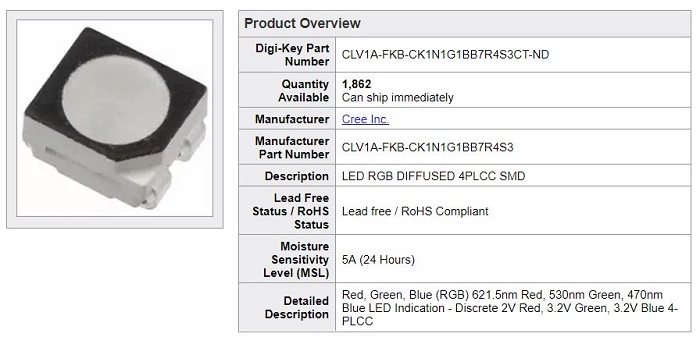
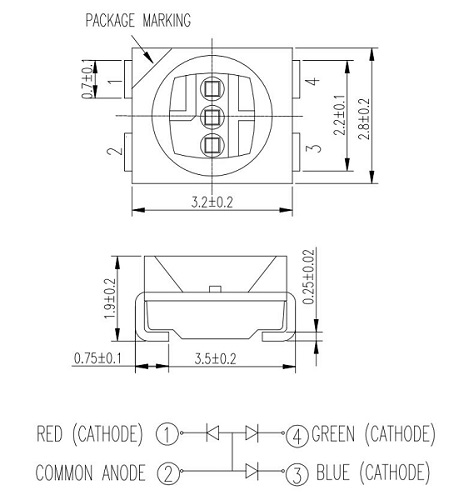
● It was a small LED component and the datasheet helped me to understand how to orient the LED and connect the same for respective colors. Also this RGB LED which I am using has four leads, one anode and three cathods. There are three cathode leads going to the positive connection of each of the single LEDs to the microcontroller and a single anode lead that is connected to all three negative sides of the LEDs.
● More or less, my workflow for component selection was based on the datasheet of the main component, I realized each major component has a ohms law or different formula for connection in a particular selection criteria which has been explained in the respective datasheets, also in terms of the other necessary components. Neil's example boards helped a great deal in understanding the significance of other components involved. It was rather an easy workflow for the RGB LED, starting with the major components and then narrowing it down to the supporting ones, it needed a microcontroller (I have been using attiny44 for this matter), an ftdi for power, an avrisp for programming, a 5V regulator, capacitor, resistor for the even flow of current and more resistors for each cathode of the RGB light for sufficient output while aslo keeping the LED safe for a longer run.
● Majority of the components in terms of the resistors and capacitors have been selected based on ohm's law as explained in detail during WEEK 07, the reason for slecting a resistor remains that it implements electrical resistance or in simple words, to reduce to current flow among other uses such as adjust signal levels, divide voltage etc and as for cacpacitor, the main reason is that it stores the electrical energy and gives this energy again to the circuit when necessary. I define a specific pin for the RGB led for each color and I program the board accordingly for respective color combinations. So also based on my recent experience, I selected the components for this week's assignment. It is indeed an interesting process to be followed and always a diversified learning experience as well.
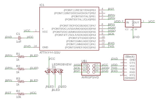
● I started to create the schematic on eagle by using the components from the fab library, all of the components apart from the RGB LED have been used by me before for previous weeks during WEEK 07 & WEEK 11 for electronics design and input devices week respectively. By now, I was much knowledgeable about the connections in the schematic, how to label the same and using the electrical check tools for any missing connections. It was not a complicated schematic to create and understand as well.
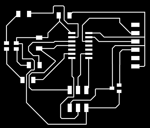
● Moving to the more essential part of the board design is the part where I start creating the traces for the board which can be milled on the Rolan Machine. So as we can see in the image below, I managed to connect all the traces correctly and exported the file in the form (.png) from Eagle.
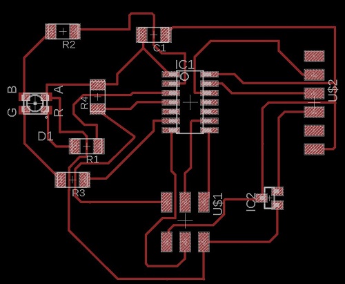
● The below image is the (.png) file for my RGB Board which I uploaded on fabmodules to follow the process of creating the (.rml) file.
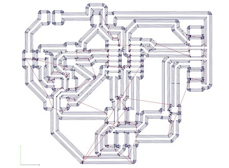
● As you can see below, we have the calculated path of the traces ready to be downloaded, after selecting the 1/64 trace option and selecting the Roland SRM-20 from the website in the form of (.rml) file to be recognized by the Vpanel software on the Roland Machine. I checked if no traces overlapped each other or if the bit would not be able to create a path at a particular junction, but it all looked achievable. I followed the same procedure to download the (.rml) file for the outline of the board.
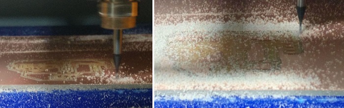
● So, I moved on to using the Vpanel and start cutting the traces and then cutting the outline for the PCB.
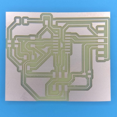
● I was more than satisfied with the result of the cutting operation of the traces and the outline for my board. So I planned on to click a cute little picture for the same.
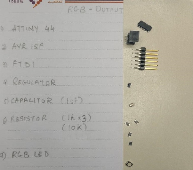
● Now comes the best part of this where I solder the required components on the board, below is the list I created which helped me to source the respective components and place them on the double sided tape. I used the
ATTINY 44 - the microcontroller
FTDI - for connection to the laptop which also is the power source
AVRISP - used for programming with the help of my FabISP
Regulator - to regulate the power at 5V for safety
Capacitor (10uF) - to capacite the current flowing from ground to vcc
Resistor (1k)x 3 - for each of the LED on the RGB LED component
Resistor (10k) - to resist the current flowing from reset to vcc
and of course,
● RGB LED - full-color LEDs which offer an high-intensity light output and a wide viewing angle from a small package, the main component of the week
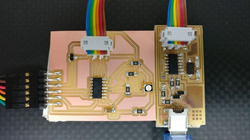
● Once the soldering was completed, in just about 20 mins this time, so I realized how better I am getting at soldering components, the next step to connect the RGB Board to the FabISP and start programming using Arduino.
● Below is again a cute picture showing how I connected the two boards to each other using the daisy cable placed on the AVRISP in the same pattern to avoid damaging the board through wrong connection. I was experienced enough now, but it is important to be aware about these little things which matter the most. I used the FTDI cable to connect the board to the laptop and the FabISP was connected through the mini USB port.
● I tested one very basic code through Arduino IDE which I created from scratch with the help of Salama and Zubair at the lab, this basic code was created to make sure all the colors were indeed showing their true colors with equal intensity.
● The code below starts with declaring the pin for specified color connected from the RGB LED component to the ATTINY 44. In my case, the Red, Green and Blue were connected to 9, 7 and 10 respectively to the analog pins on the microcontroller.
● Then, the void setup routine is used to initialize the specified LED pins through pinMode function for specified LED color output.
● And, by creating the void loop routine which is the function which runs over and over again, in which the analogwrite function was used to set the brightness of each LED using the values from 0 - 255, where 0 is OFF and 255 is ON at high intensity or maximum brightness. So, I specify each LED color for analogwrite with a delay of 100 milliseconds between each one of them. And the loop continues forever.
● Download the Arduino code for RGB LED test 1 HERE
rgb test 1
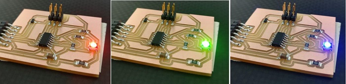
● The program was uploaded and the LED output made me SMILE, so once again a cute picture with the LED displayed as
R G B :)
RGB test #1 video
One more interesting test with more colors
● This particular LINK for the tutorial and also the source for the code download, was very interesting and followed the same for the second test code for the RGB LED.● And as explained before, the RGB LED which I am using has four leads. There is one lead going to the positive connection of each of the single LEDs within the package and a single lead that is connected to all three negative sides of the LEDs. Which also means with a common anode you connect the anode to the +5v and each individual LED to a resistor each. Connect that resistor to an output pin.
● I modified the code by uncommenting the command for defining the common anode function as the RGB LED I am using has a common anode, if at all I dont uncomment that particular anode defining command, then I notice a missing color either Red, Green or Blue from the RGB LED after uploading the code. So it is of utmost importance to #define COMMON_ANODE when using this particular RGB, I totally missed out this particular part and command at first, I could see the difference in result. After uncommenting the same I could see all the colors from the RGB LED working perfectly fine as per the code uploaded.
● I also added more color to the code, such as brown, cyan and teal apart from the original set of colors. And I also changed the code according to the pins connected from the ATtiny44 to the RGB LED.
● If I set the brightness of all three LEDs to be the same, then the overall color of the light will be white. If we turn off the blue LED, so that just the red and green LEDs are the same brightness, then the light will appear yellow. I can control the brightness of each of the red, green and blue parts of the LED separately, making it possible to mix any color I like, which is amazing, isn't it. Hahahaha, some interesting stuff coming up.
● The following test sketch will allow me to cycle through the colors red, green, blue, yellow, purple, and aqua. These colors being some of the standard Internet colors. The sketch like the test 1 sketch starts by specifying which pins are going to be used for each of the colors: in my case these are the same pins I specified in the first test as well ...
● The next step is to write the 'setup' function. As I have learnt in earlier lessons, the setup function runs just once after the Arduino has reset. In this case, all it has to do is define the three pins I are using as being outputs. This function takes three arguments, one for the brightness of the red, green and blue LEDs. In each case the number will be in the range 0 to 255, where 0 means off and 255 means maximum brightness. The function then calls 'analogWrite' to set the brightness of each LED.
● If you look at the 'loop' function you can see that I am setting the amount of red, green and blue light that I want to display and then pausing for 1000 milliseconds which is 1 second delay before moving on to the next color.
● Download the modified Arduino code for RGB LED test 2 HERE
rgb test 2
● The program was successfully uploaded on the LED output board and below is a small video showing the same.
RGB test #2 video
learning outcomes
● Download the eagle -Board and Schematic file for my RGB LED HERE
● Download the (.png) file for my RGB LED HERE
● One more interesting week comes to an end, and I keep on gaining tremendous amount of knowledge through the process. I personally enjoyed working on the assignment for this week and wish to experiment much more with LEDs for the final project development WEEK as well.
● It's been amazing to work on electronics design and production for two weeks back to back, I am getting really comfortable at it and the aspects of selecting the components, soldering them, testing the board and programming it to do something.
● I am looking forward to the coming week's, and learn more each day of this course, especially the electronicss part, because it is indeed a new world of exploration to me and I am loving it.