ChessOne part of the assignment for this week was to design something parametric and cut it out.
This chess board I have made for the Fundamental of Digital Fabrication with detailed documentation, so i have decided to use it.
Epilog
In FabLab we have got at least 2 of them, that we are allowed to use.
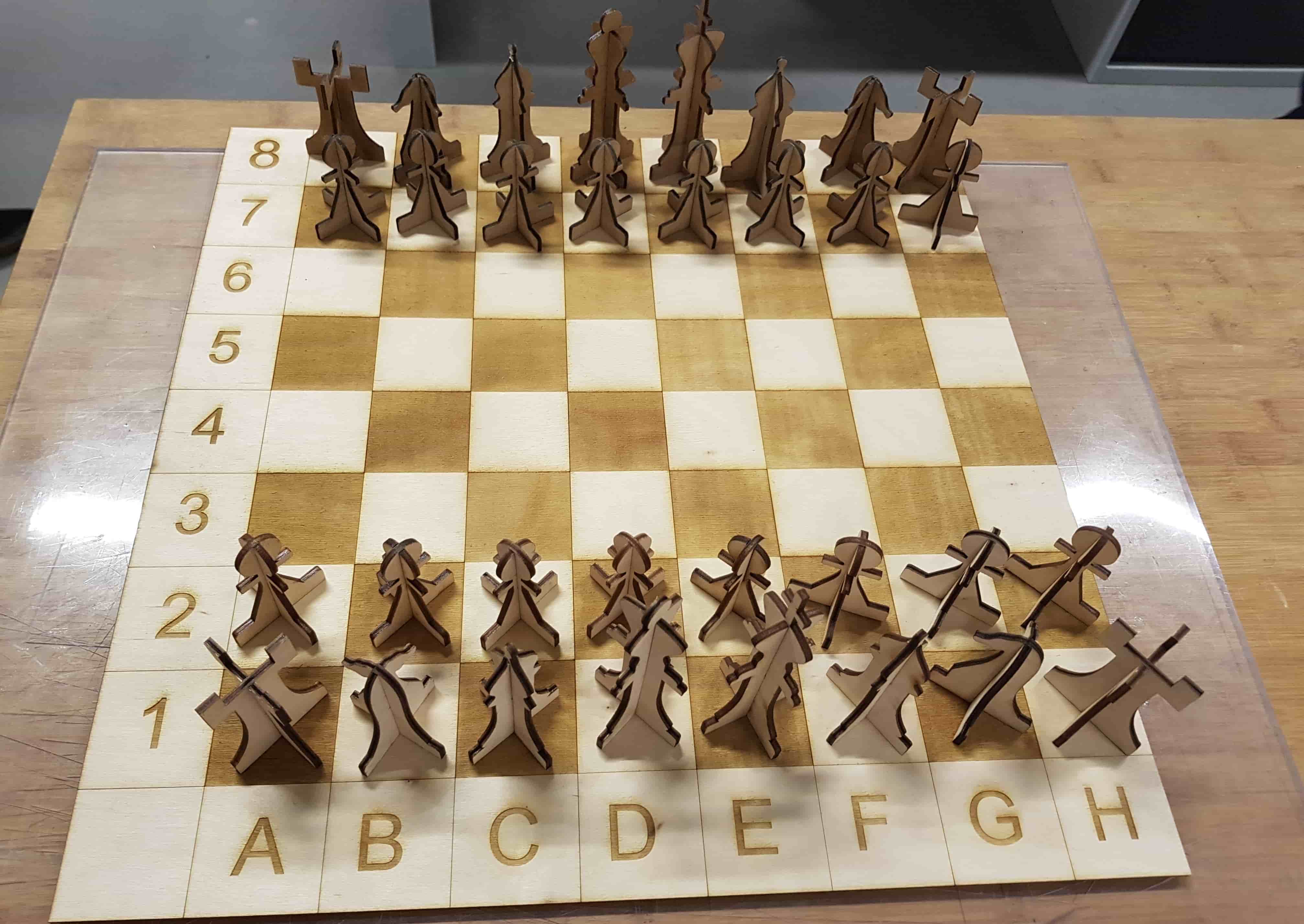
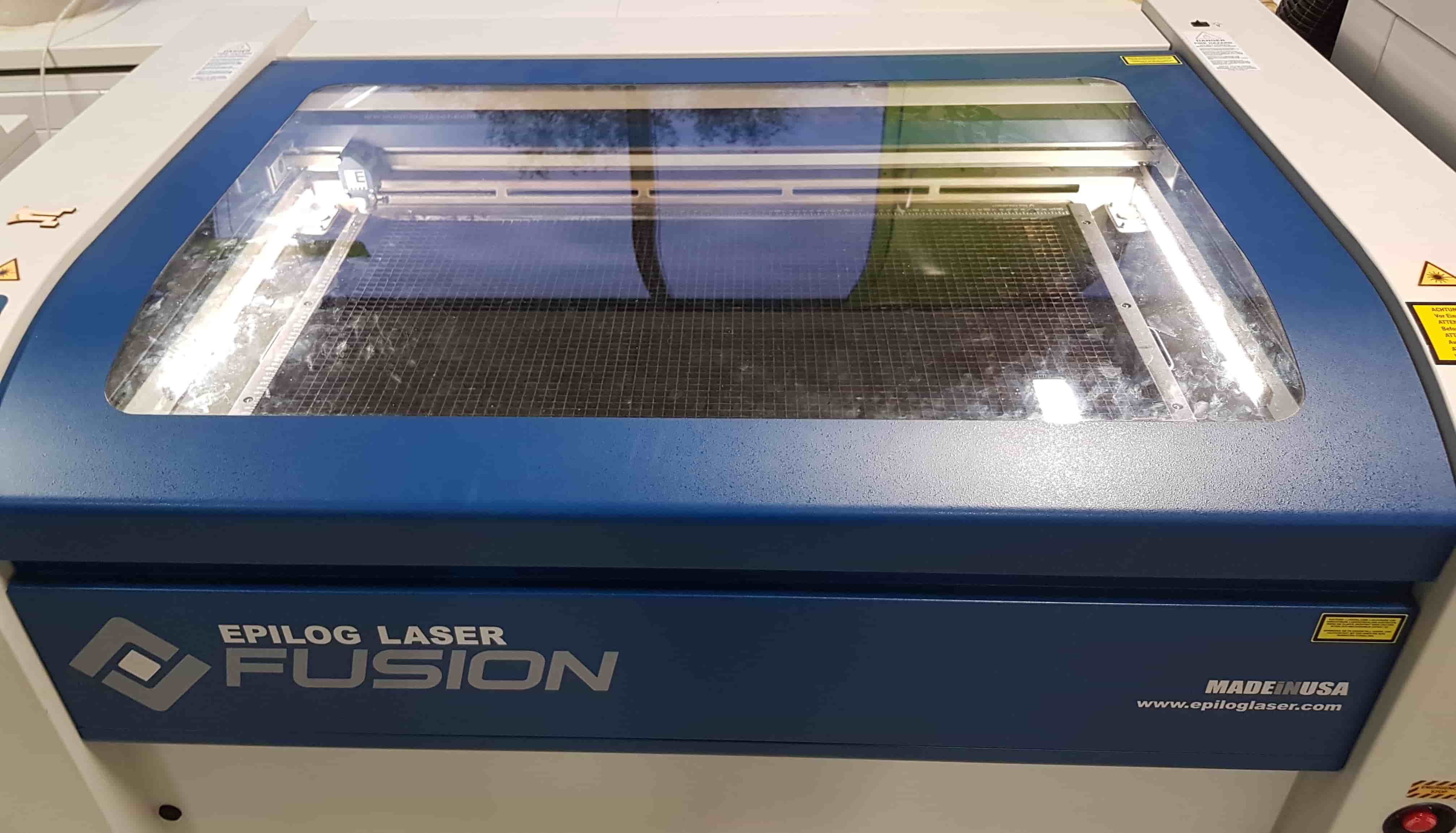
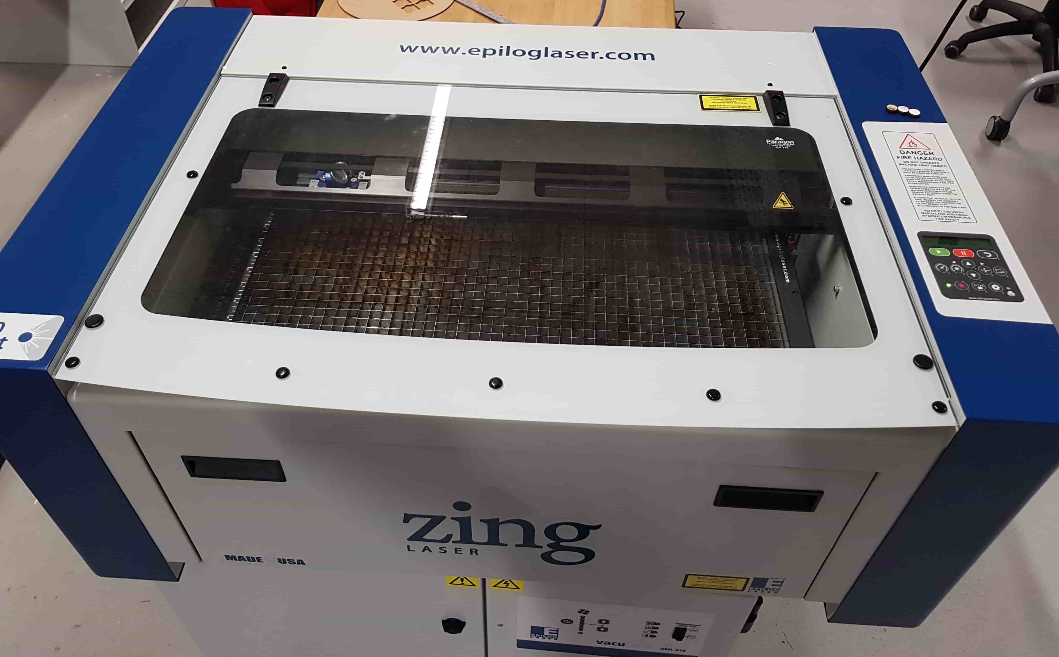
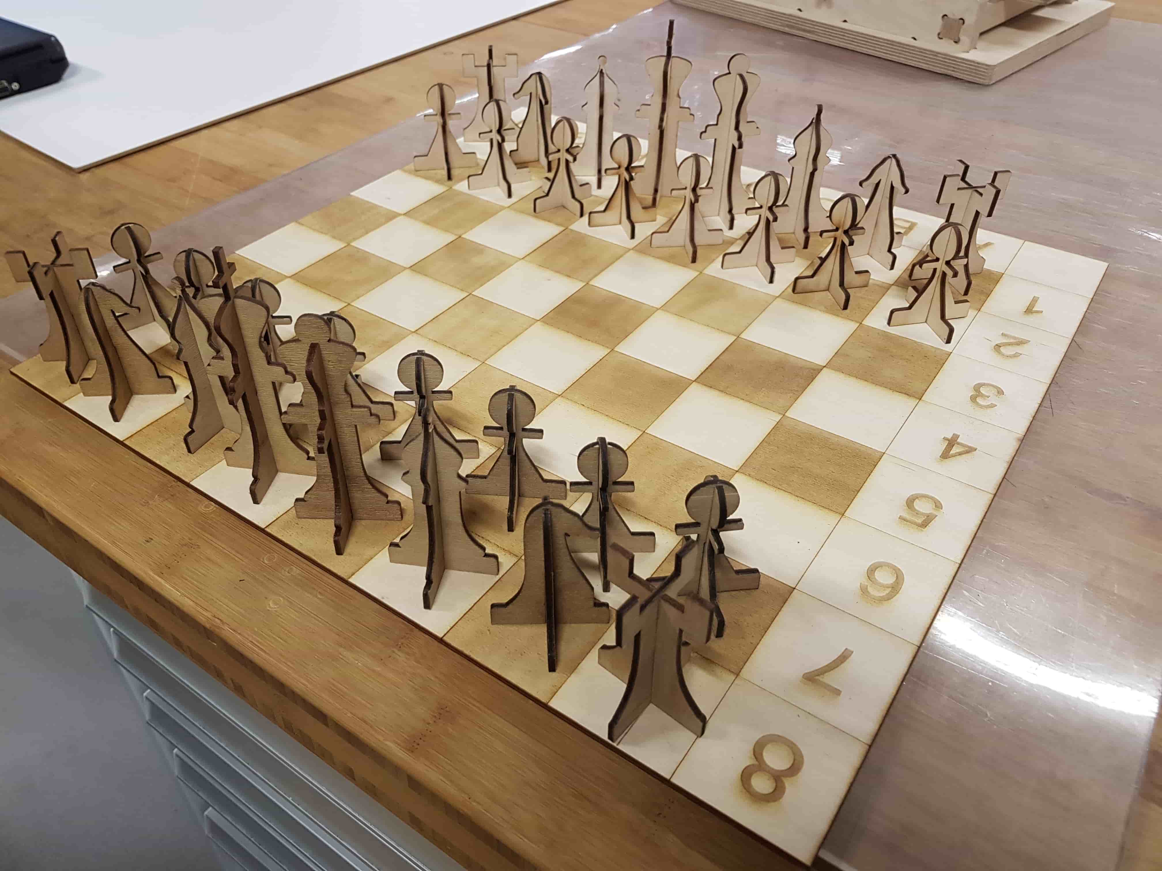
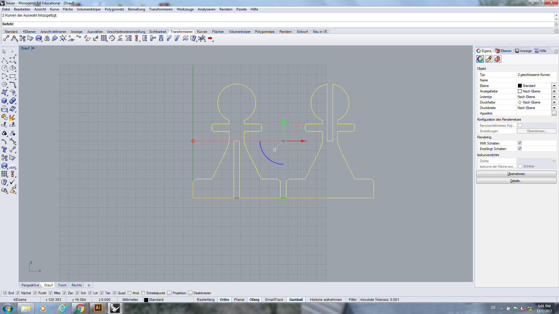
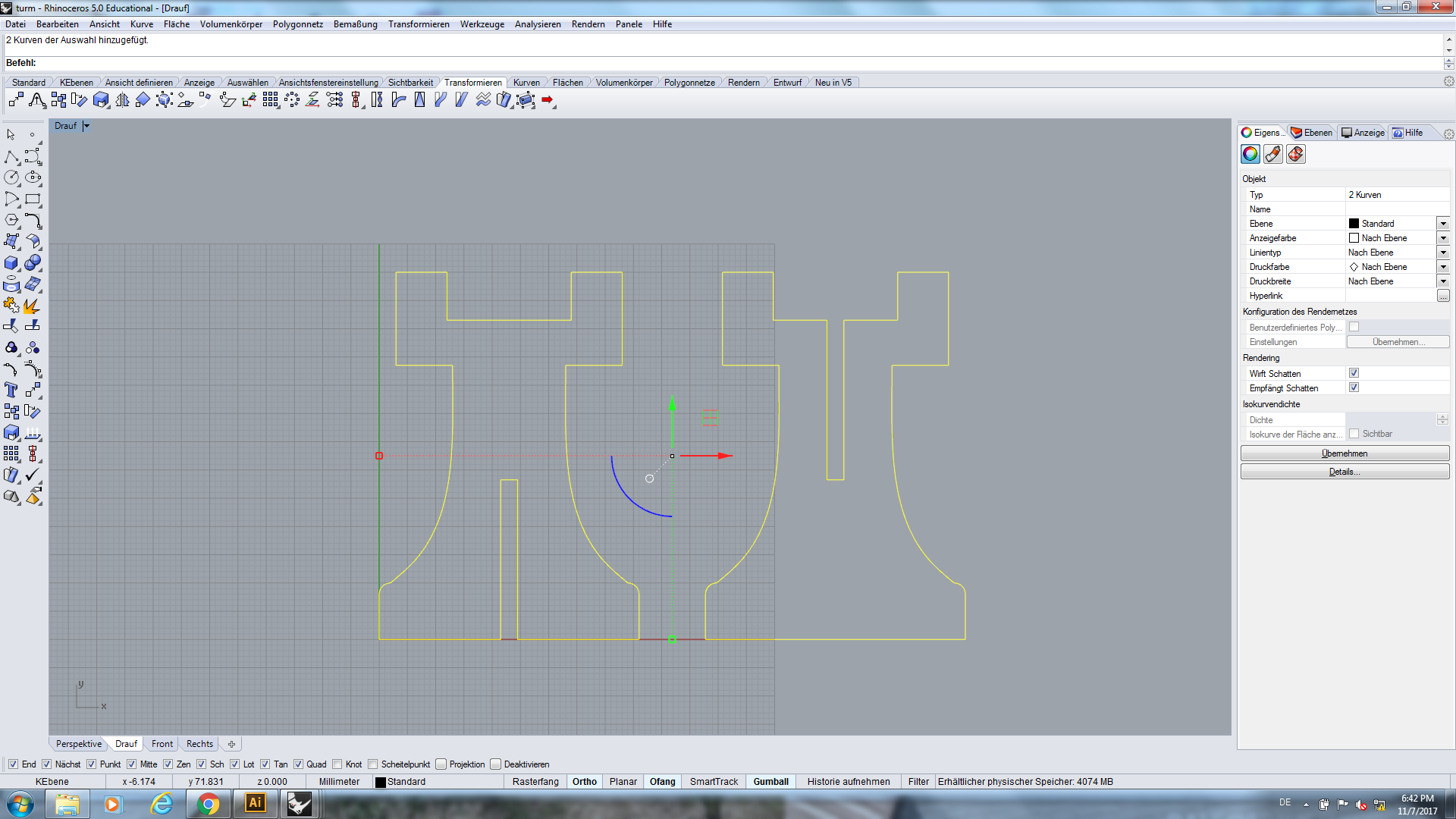
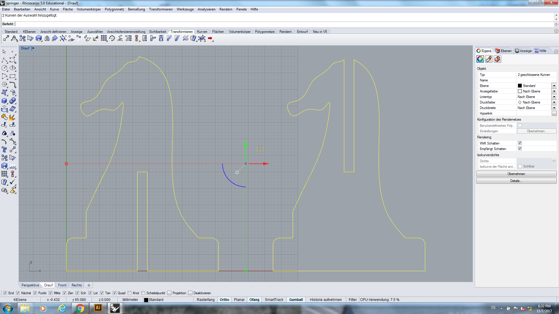
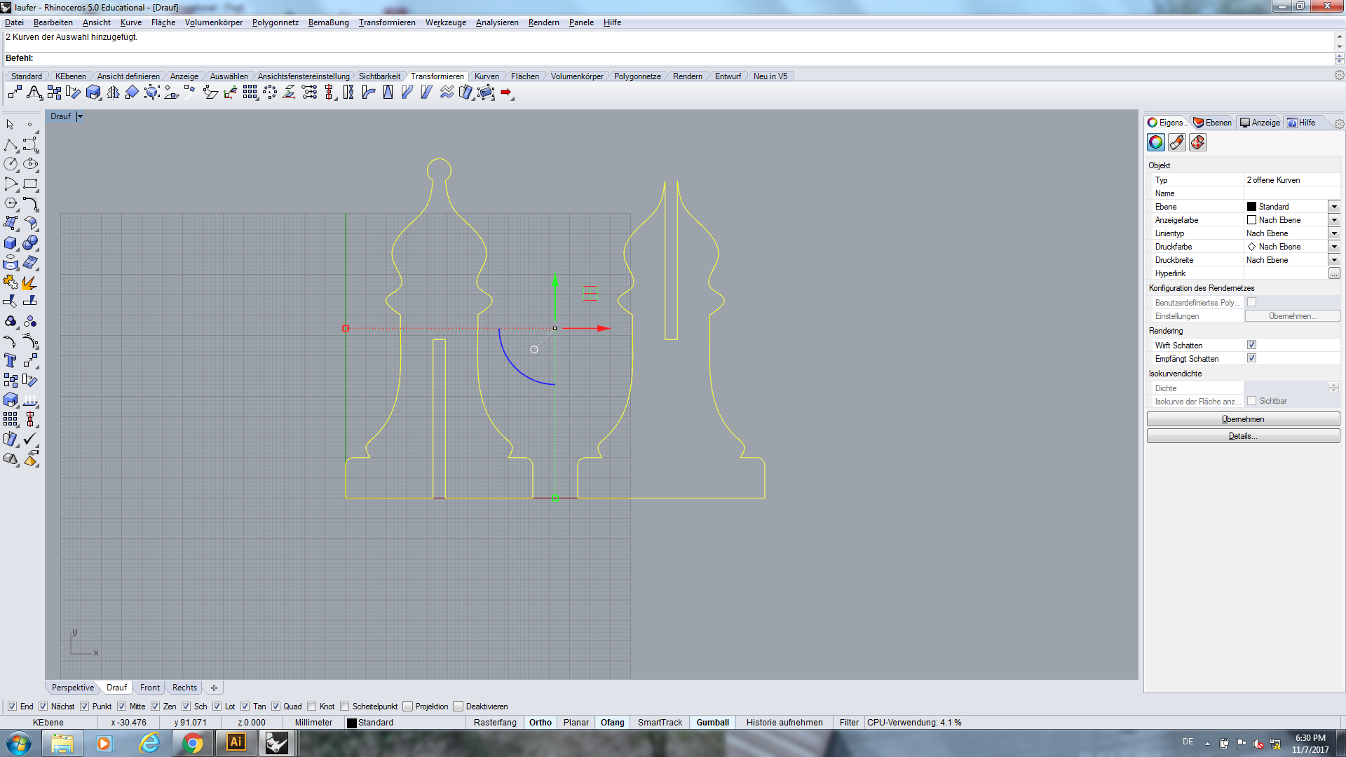
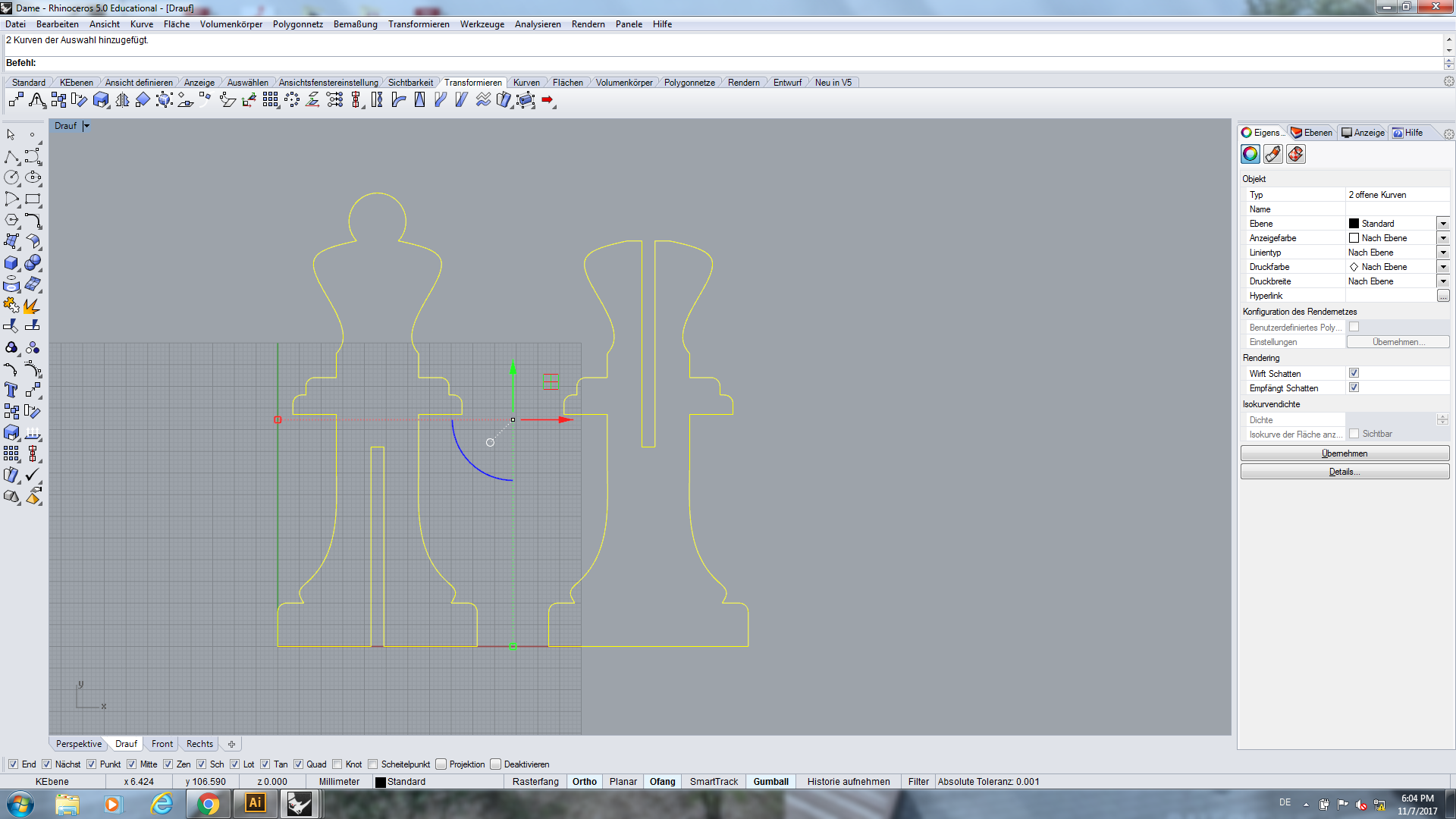
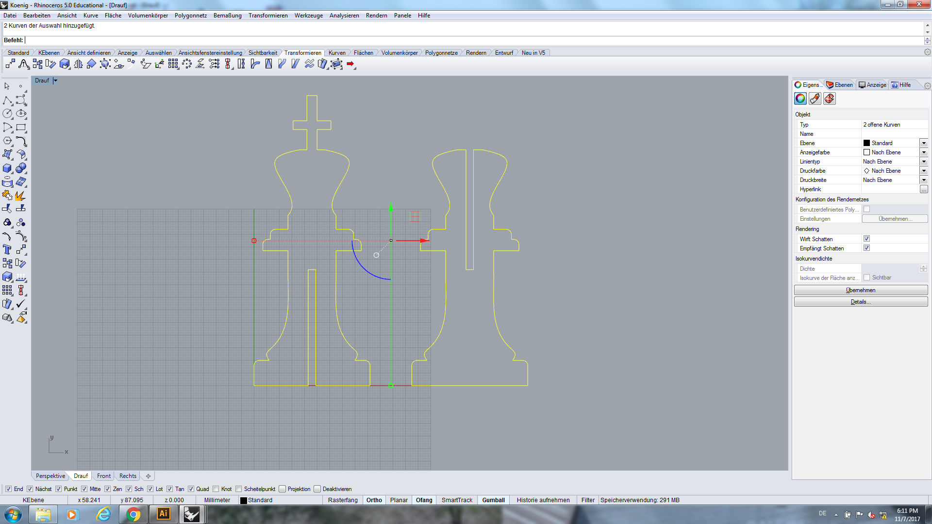
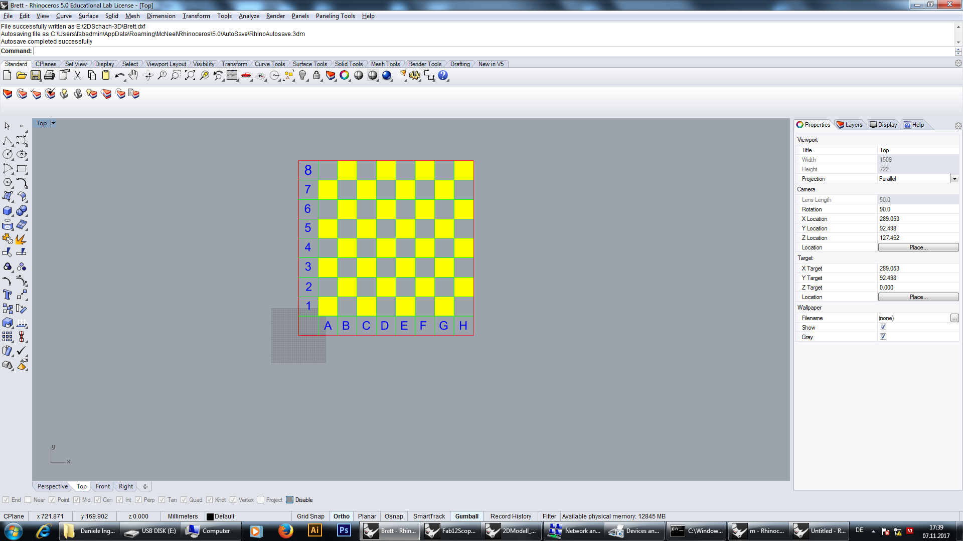
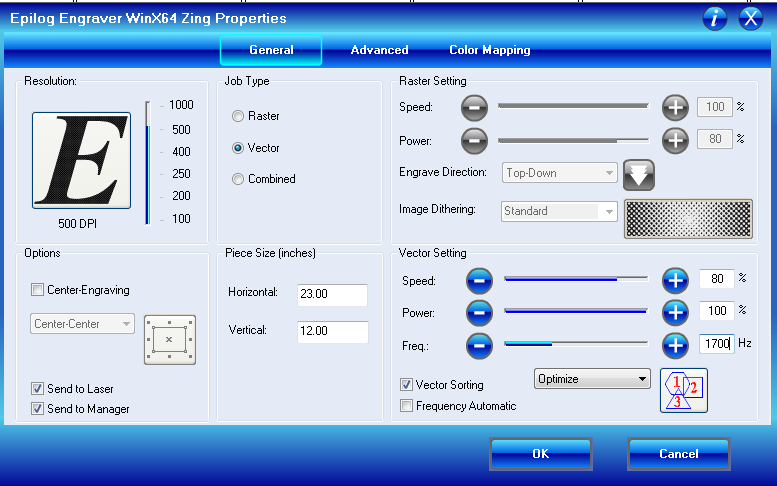
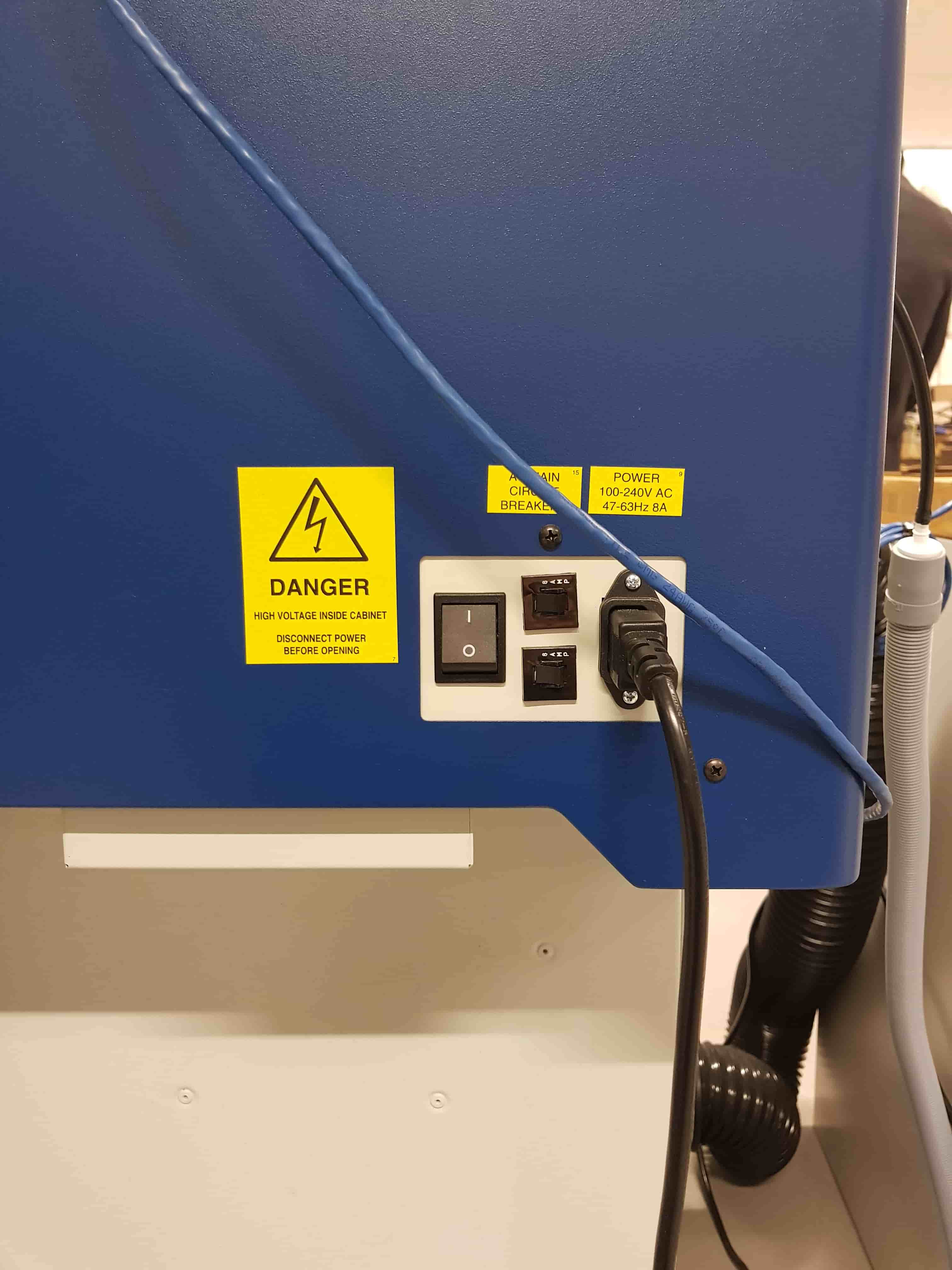
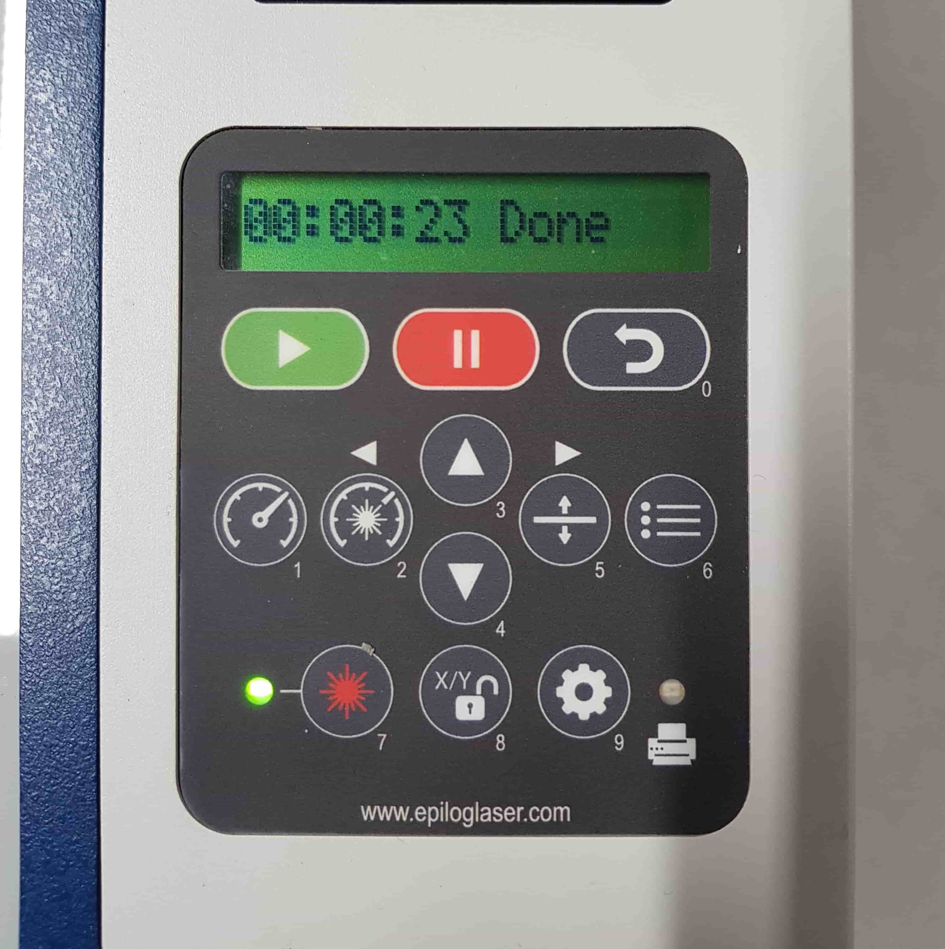
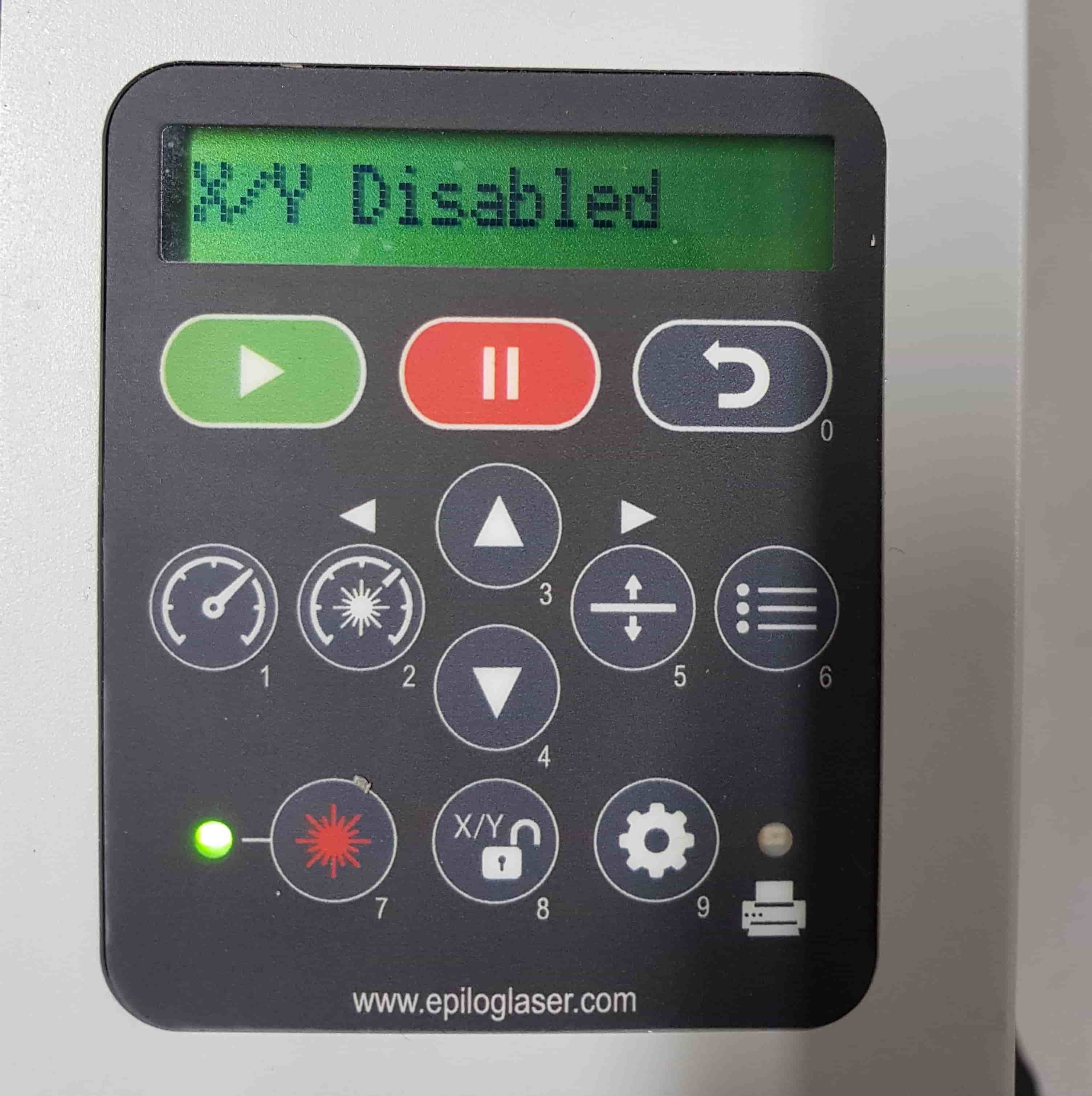
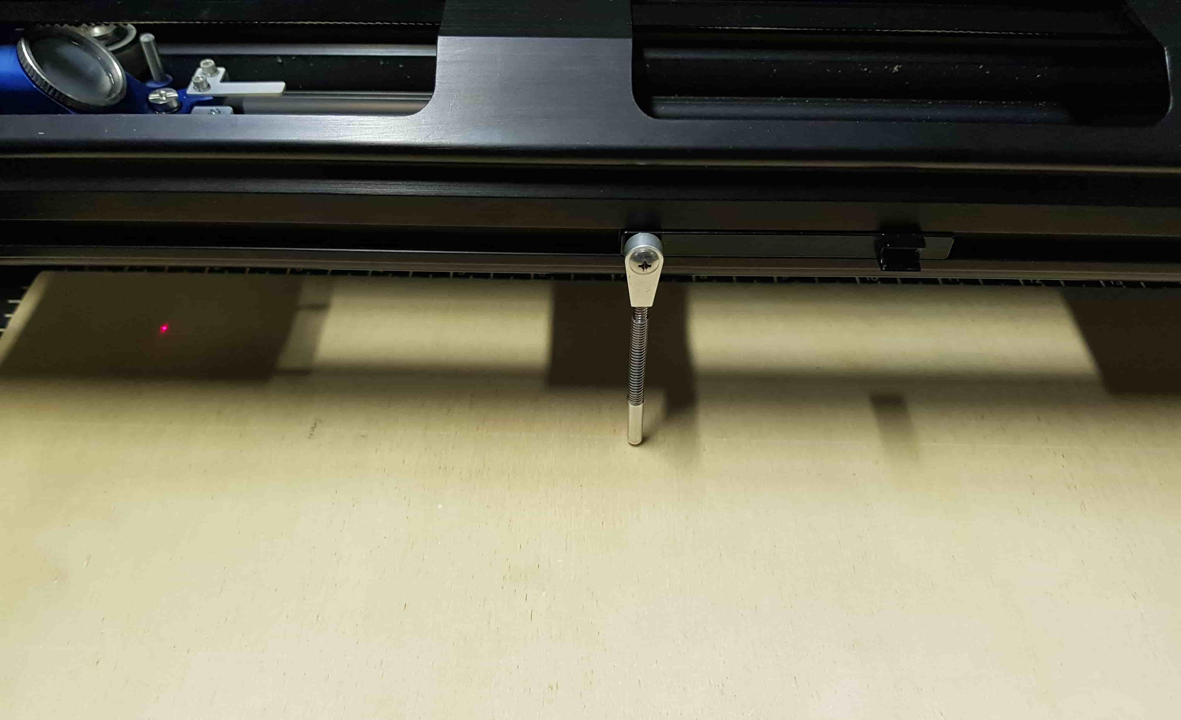
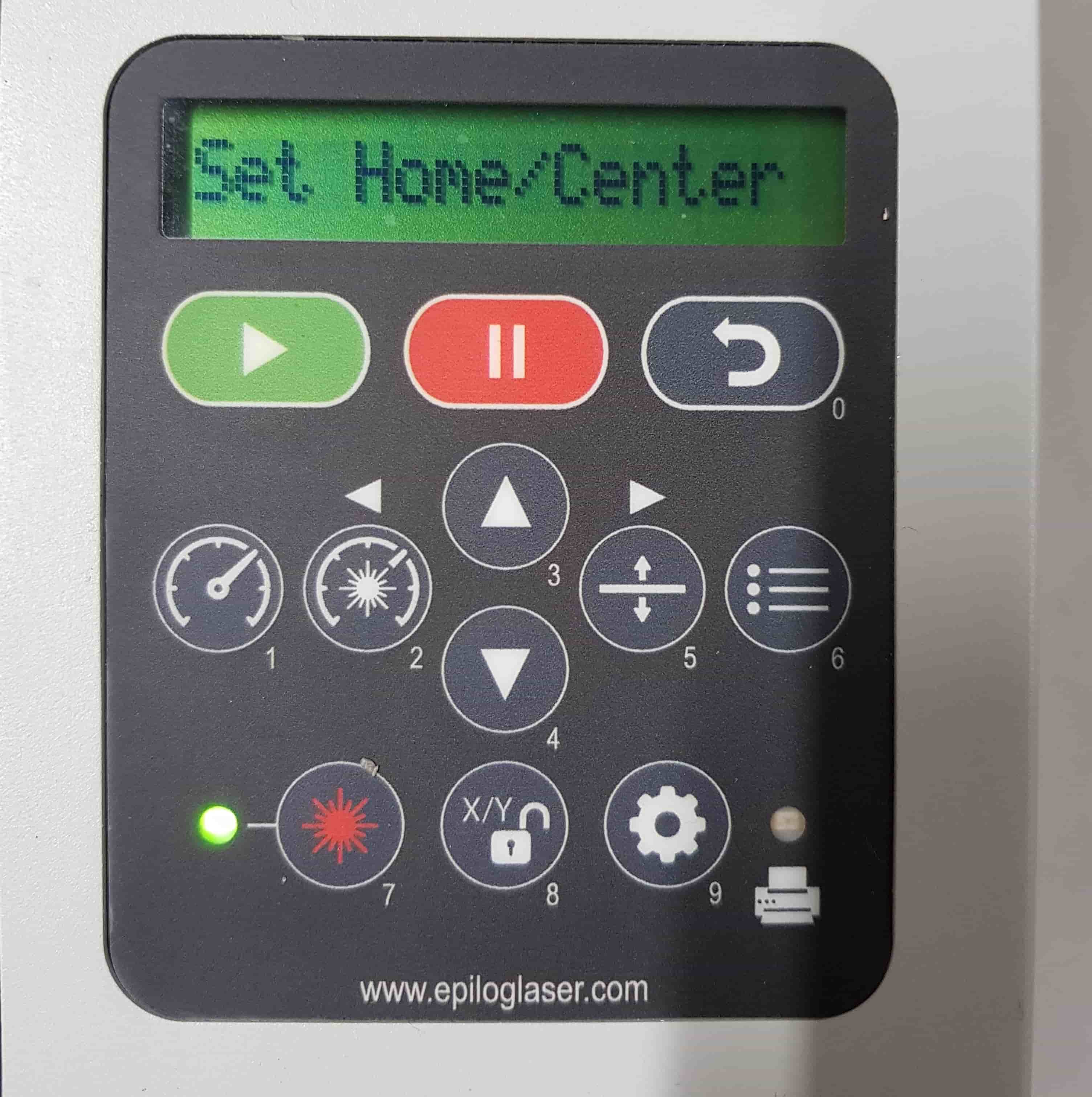
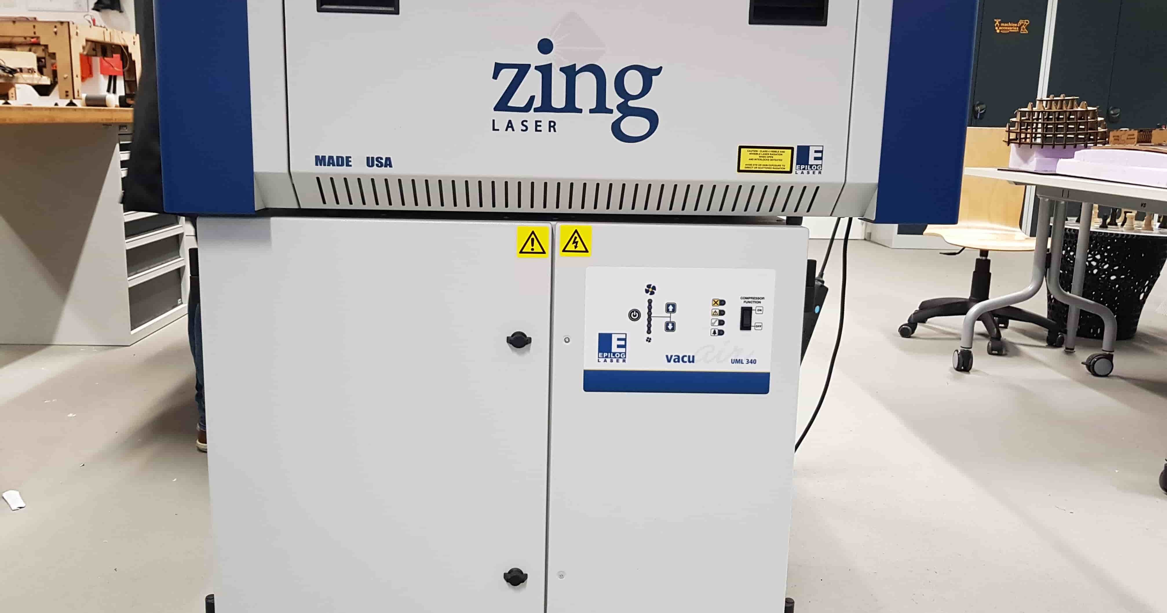
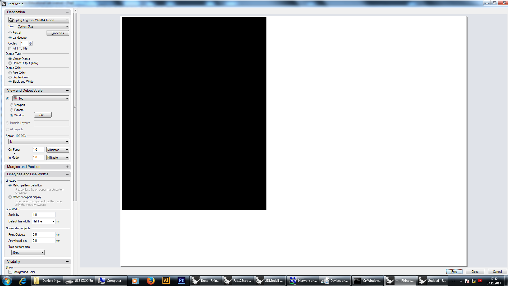
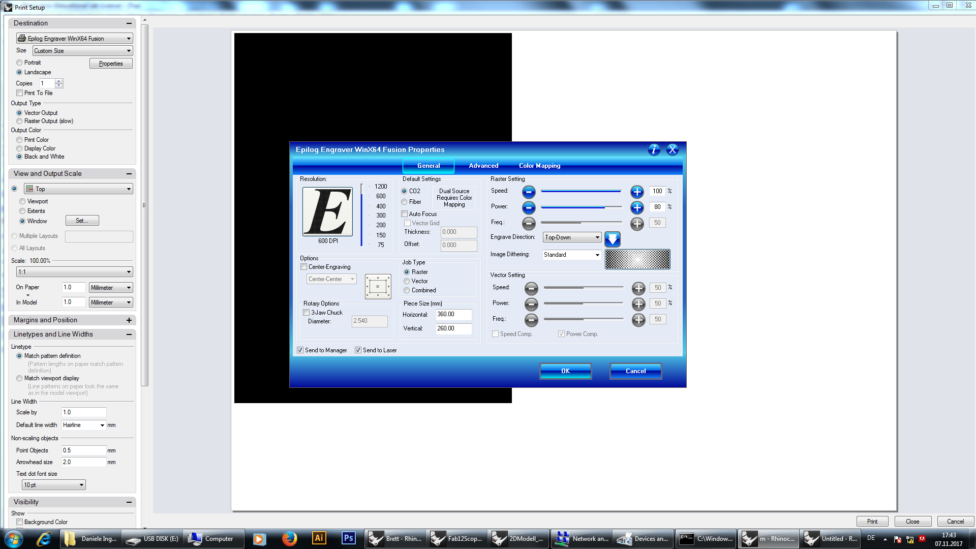
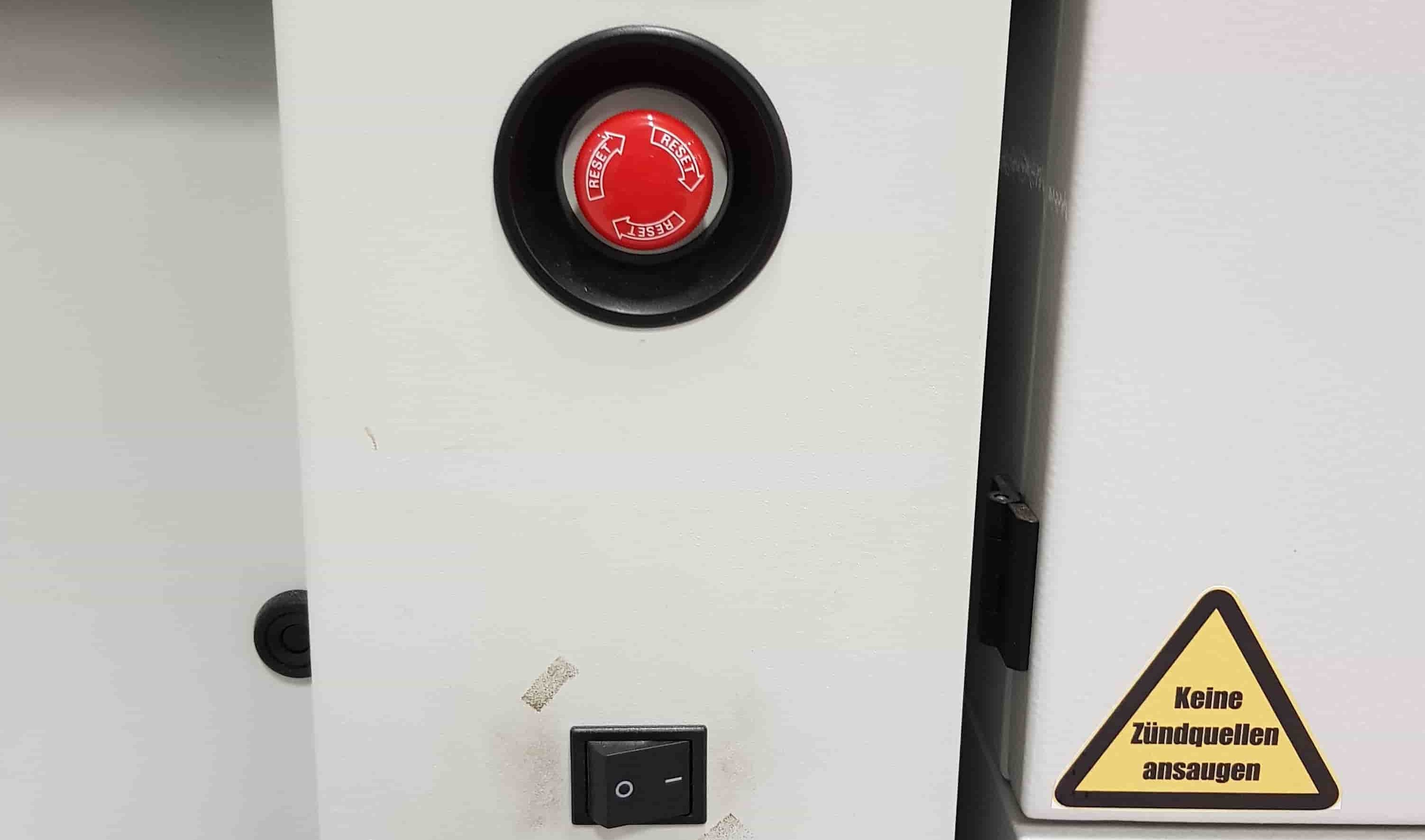
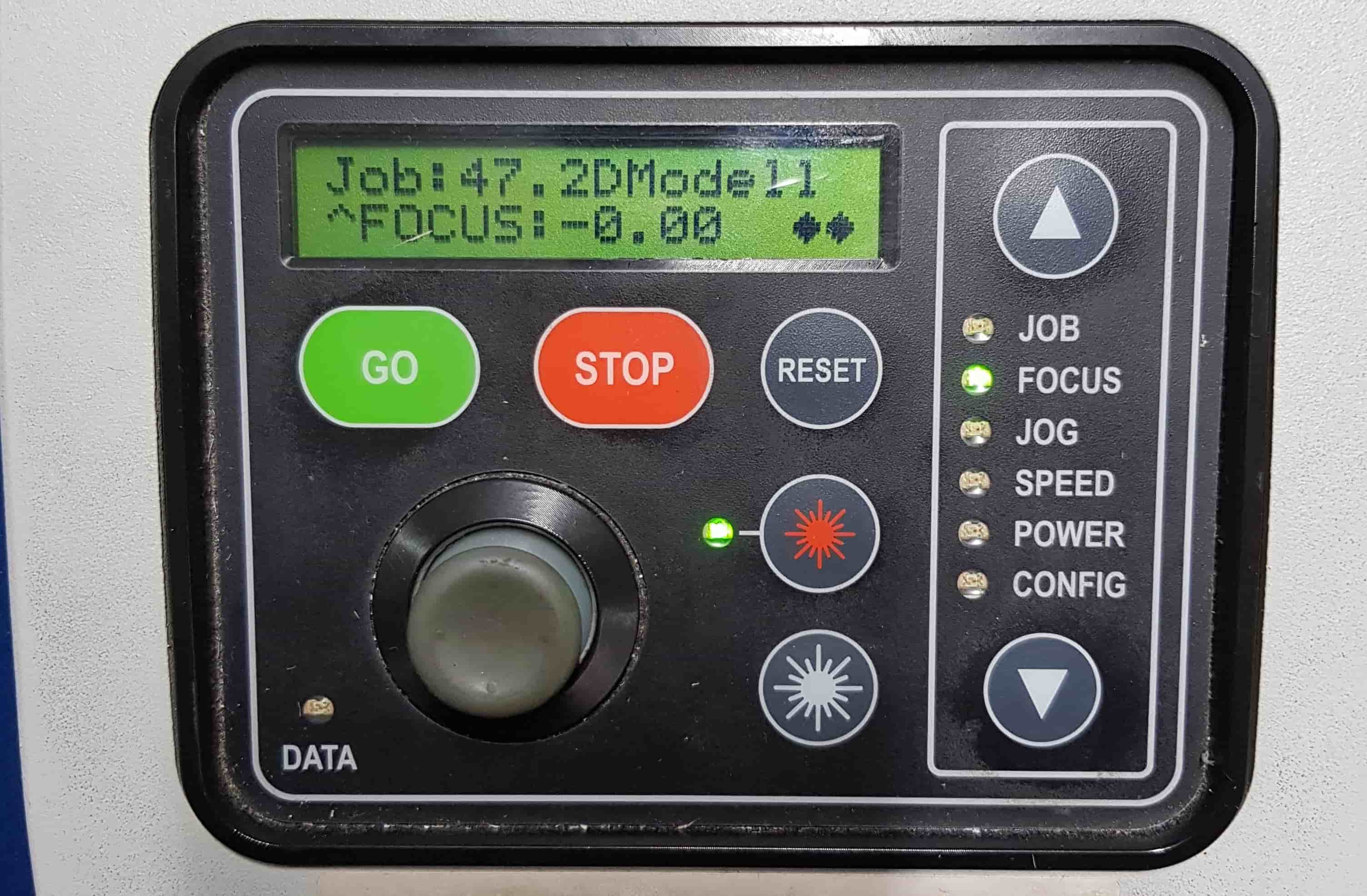
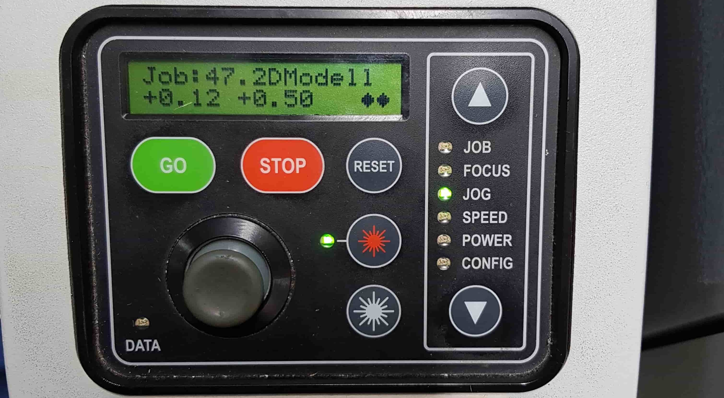
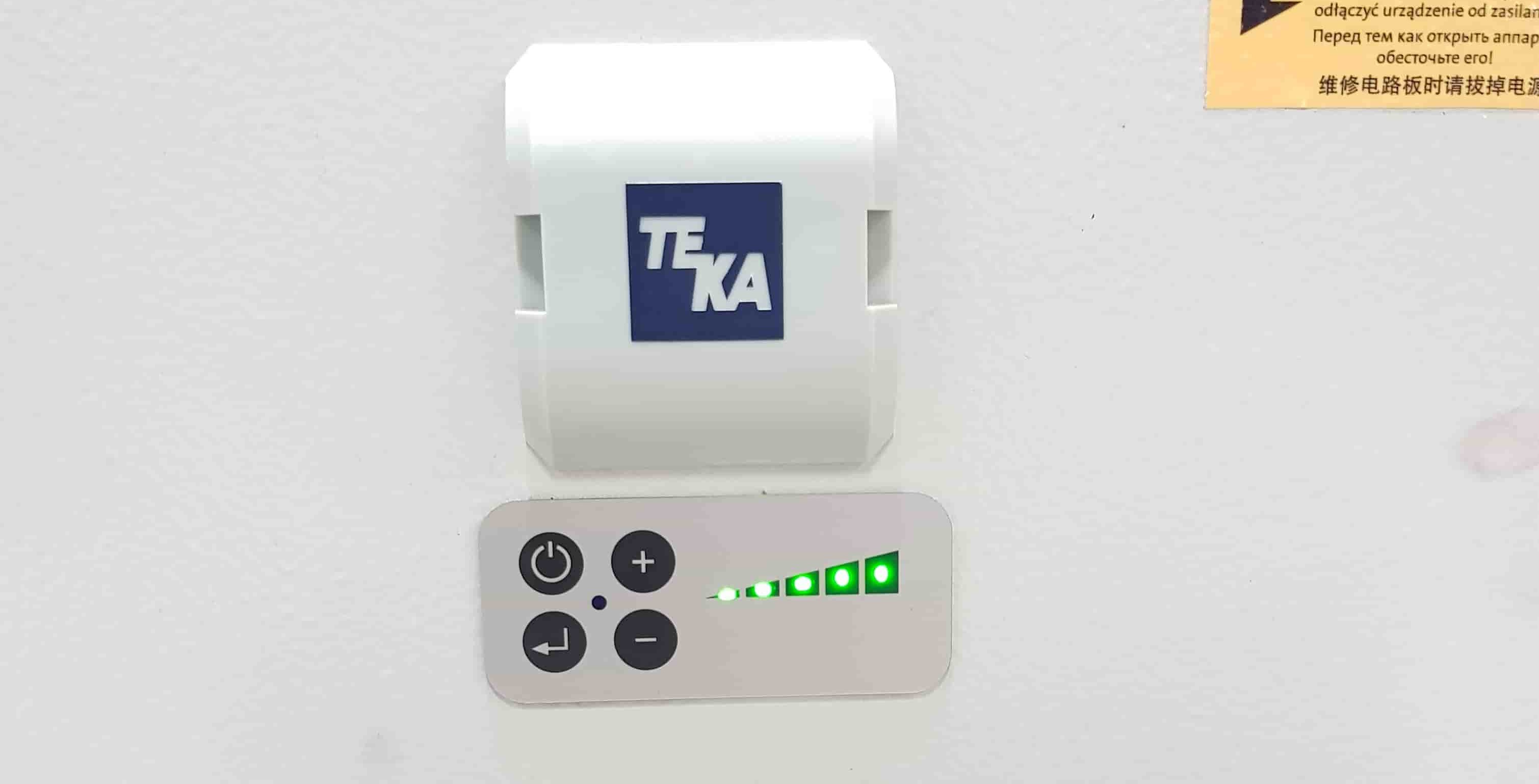
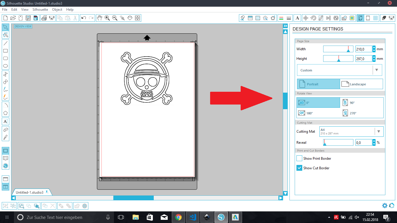
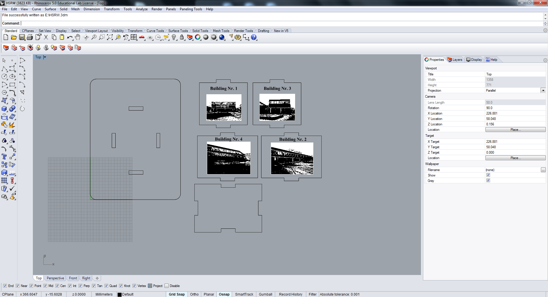
This is the Big OneEpilog Zing 30 WattAnd the small oneChessBelow you can see my finished ProjektPawnHere is the Sketch of the pawn i have madeRockHere is the Rock of the pawn i have madeKnightHere is the Sketch of the knight i have madeBishopHere is the Sketch of the bishop i have madeQueenHere is the Sketch of the Queen i have madeKingHere is the Sketch of the King i have madeBoardAfter I have done all the figure it was time to make a board. First i made it in DraftSight. The squares are 50 mm high and 50 mm wide.There are some additional stripes, those squares were reserved for the numbers and letters. Yellow, blue and green layers stand for Raster and Red for the Vektor. After we have all the models it is time to cut them, therefore we have have two machines that i mentioned earlier The global explotation of the machines are similar. First we have to turn it on, set the focus and jog, turn the 'vacuum cleaner' on, send the from PC and go don't worry I will explain each step below for each machine.BoardFirst I made the Figures. For the figures I've use a small machineOkay, fist of all we have to set a printing options, therefore press Ctrl + P and then 'Properties' and it will open this blue window. Here You can set a piece size in this machine in inches in the big one in mm. Our job type ist Vektoring - Cutting settings are by 80% speed, 100% power and 1700 Freq.Epilog Zing 30 Watt StartNow we have to start a 'small' Laser Cutter.FocusAfter we set the proper settings and started the machine we can go to the machine, and set a focus. Go to the machine and press the middle button at the bottom of the menu panelFocus & JoGNow the Display should show: 'X/Y Disabled' it means you can change the focus and the jog.Focus & JoGTo set a focus, you should use arrows on the menu panel of the mashine. But how do we know, if the focus set properly? Well you can see the gray pin on the picture below, this pin should barely touch the surface of your board. To set a jog we have to move the head of the Laser Cutter(small one) manually. On the belt for the x axis and the crossbar for the y axis.ConfirmAfter that press the green button on the machine menu panel, and it should show: 'Set Home/Center'. Now we can go to the PC send a file.ImportantNow, very Important -> turn the 'vacuum cleaner' of the machine on and then you can start the job.EngraveNow we need to angrave black figures, Therefor I've made a rectangle. And puted my figures on the machiene -> they have to fit to the rect. It ist one of three sizes shown on picture belowEngarve SettingEpilogI have done it in a big Laser Cutting machine. So here you can see the emegensy button and the power button of the 'Big-Laser Cutter'Focus-EpilogIt always takes a time to start a Laser Cutter. Now put your material in Laser Cutter. At the left side of the menu panel you can see the arrow to choose the option you wonna do So first we gonna set a focus.Therefore we take the 'triangle' and hang it on the head of the Laser Cutter.Then Close the Door, otherwise we would not be able to do any Modification! Look to the menu Panel, select 'focus' with the arrows and move the joystick up and down. The triangle should barely touch the surface of the panel you wonna work with. After you have set focus, just press on the joystick, and the machine will remember the position.Jog-EilogThen you can switch to jog with the arrows and again use the joystick to move the head
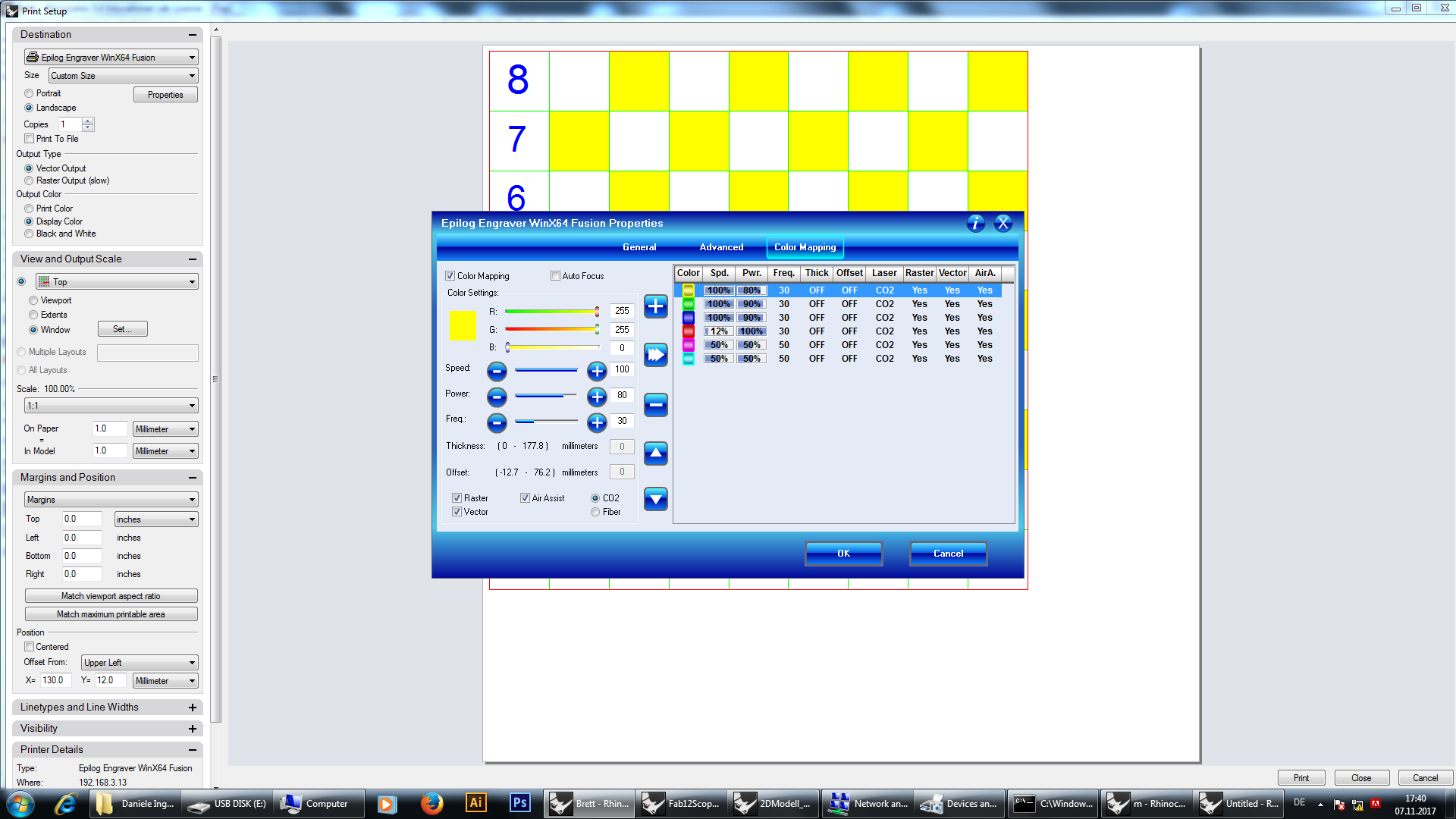
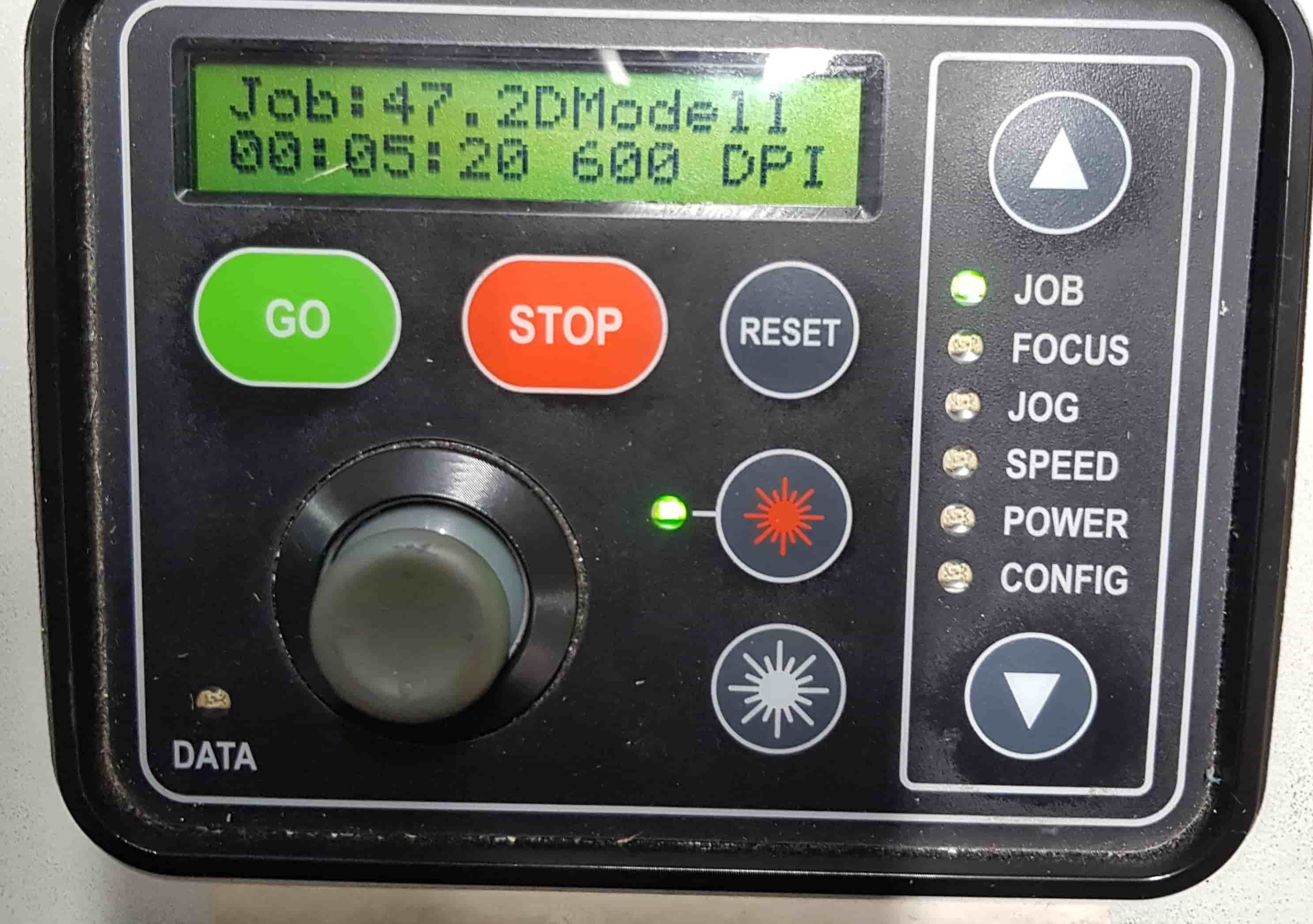
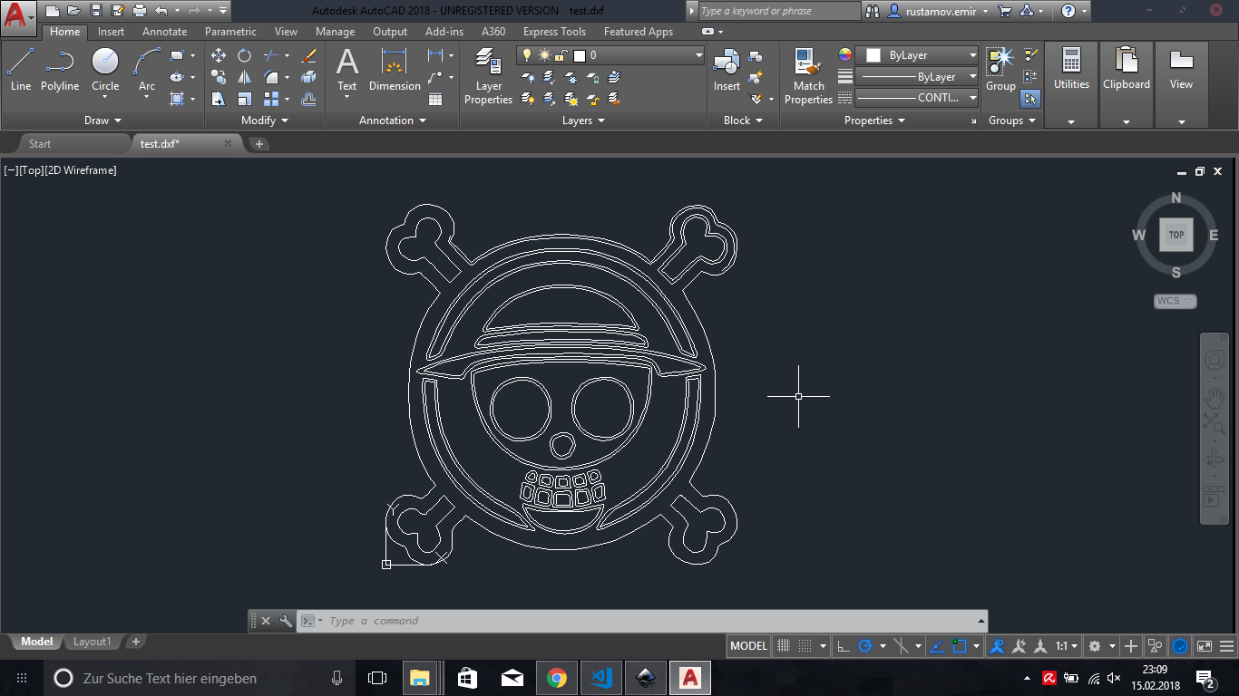
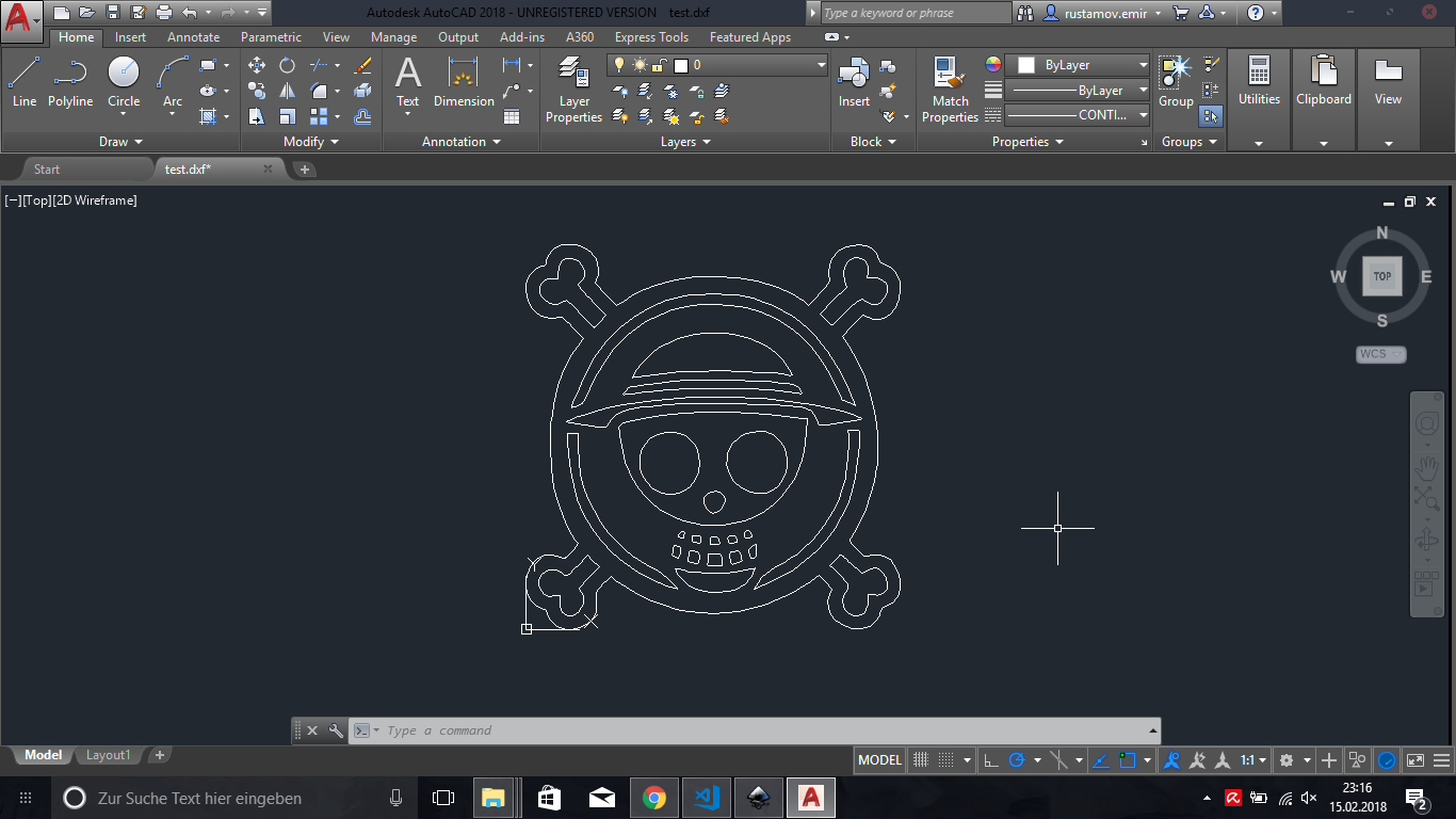
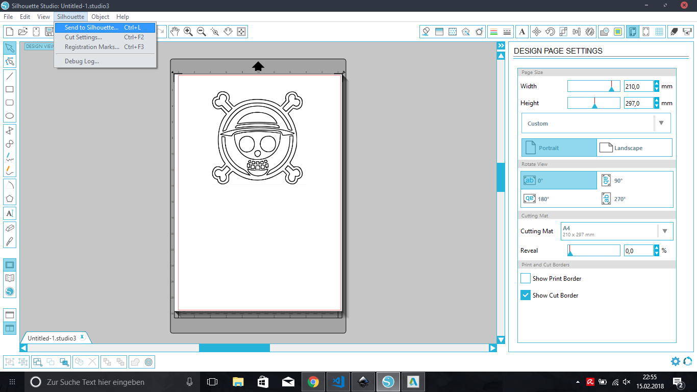
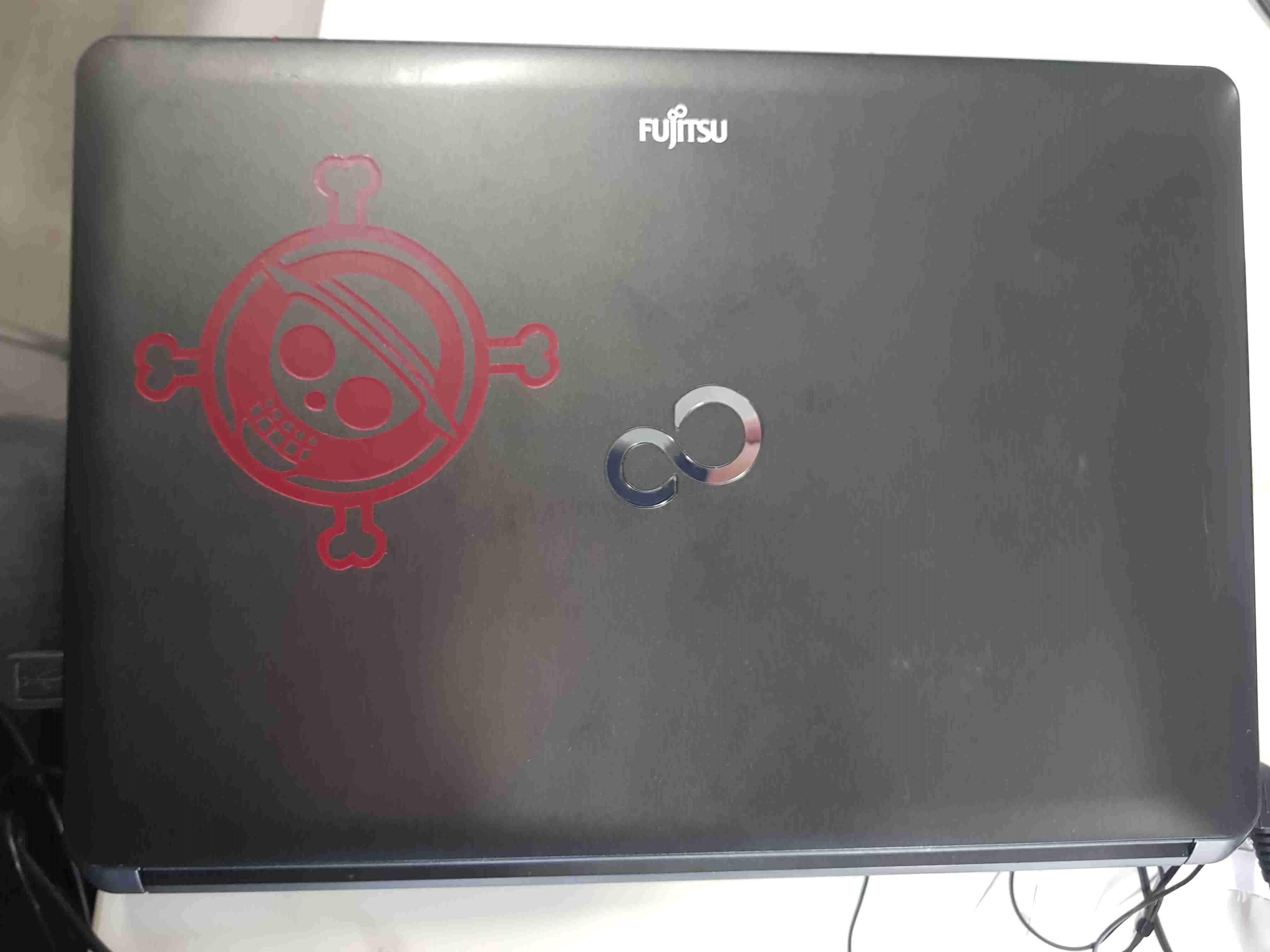
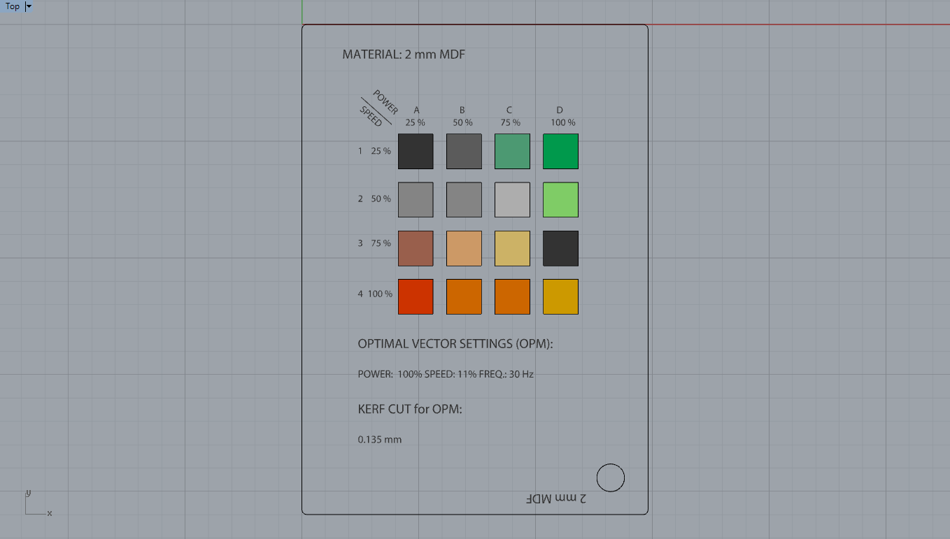
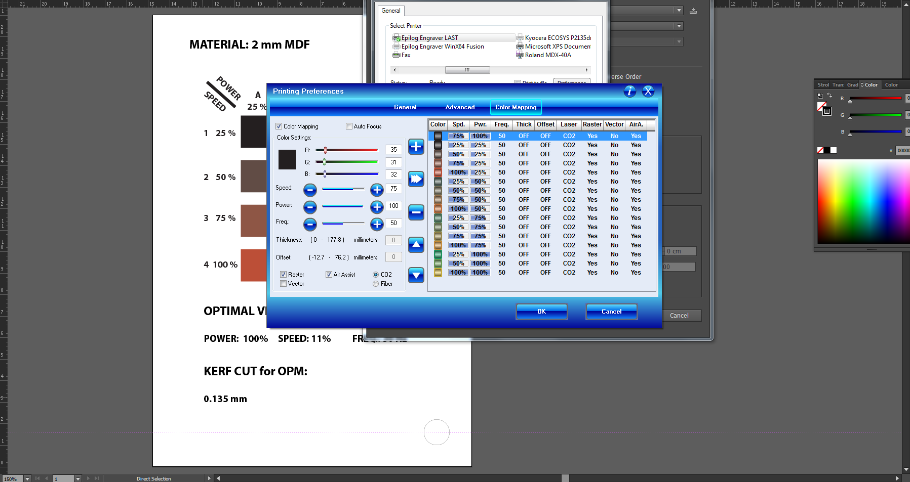
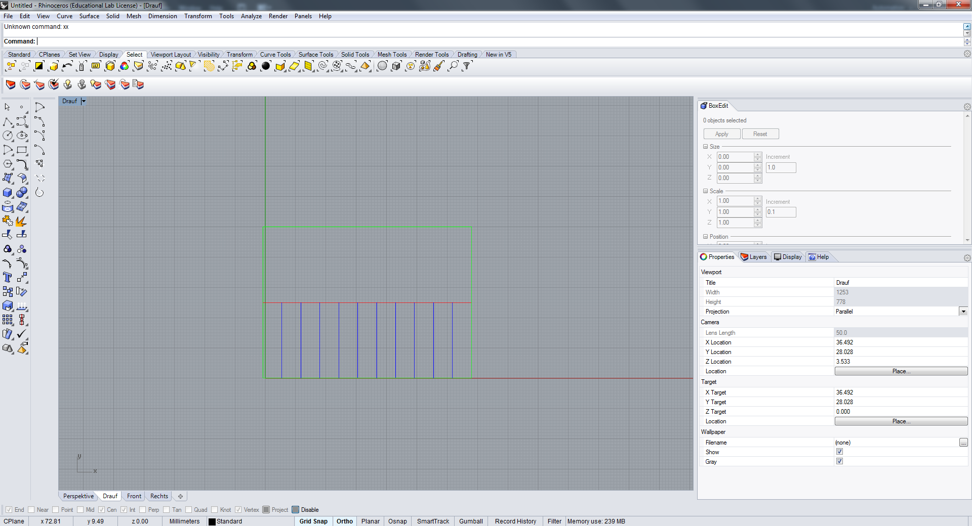
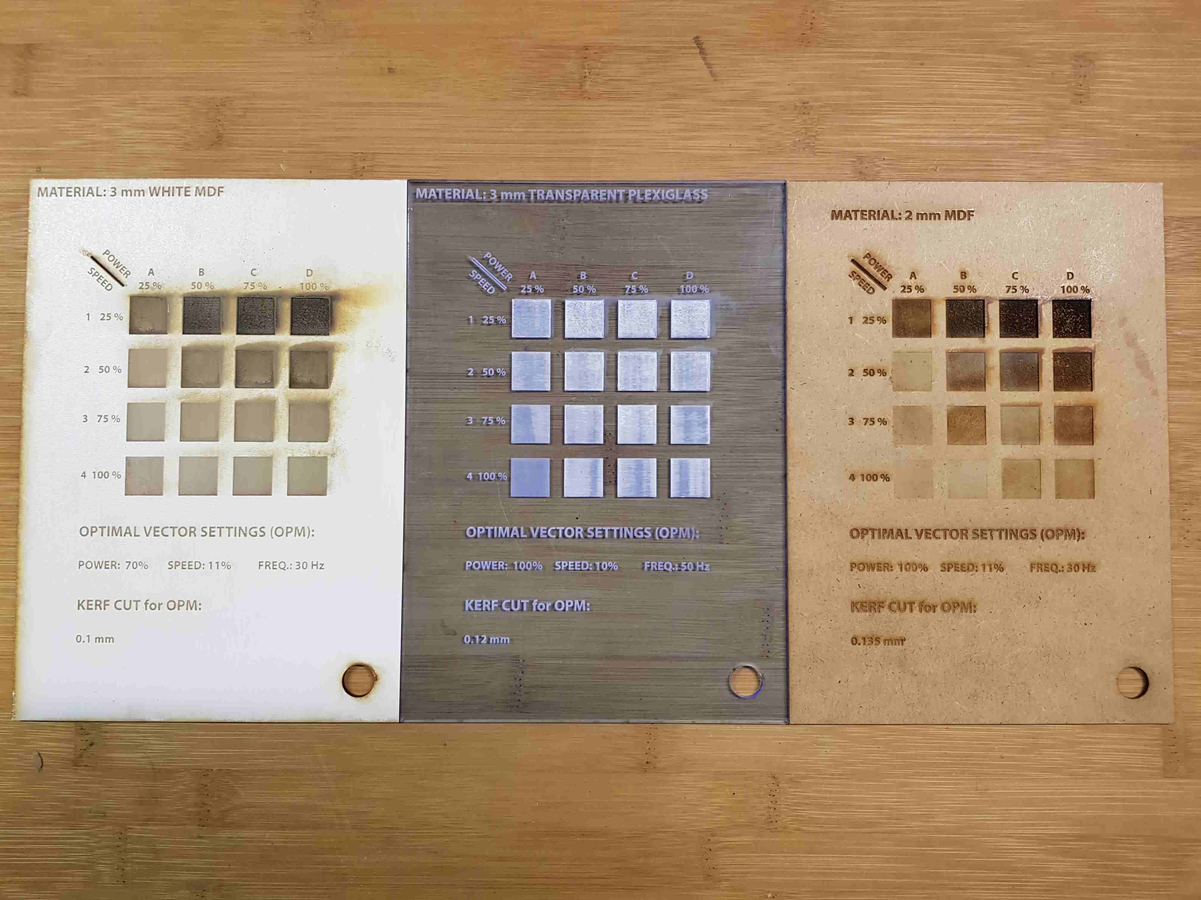
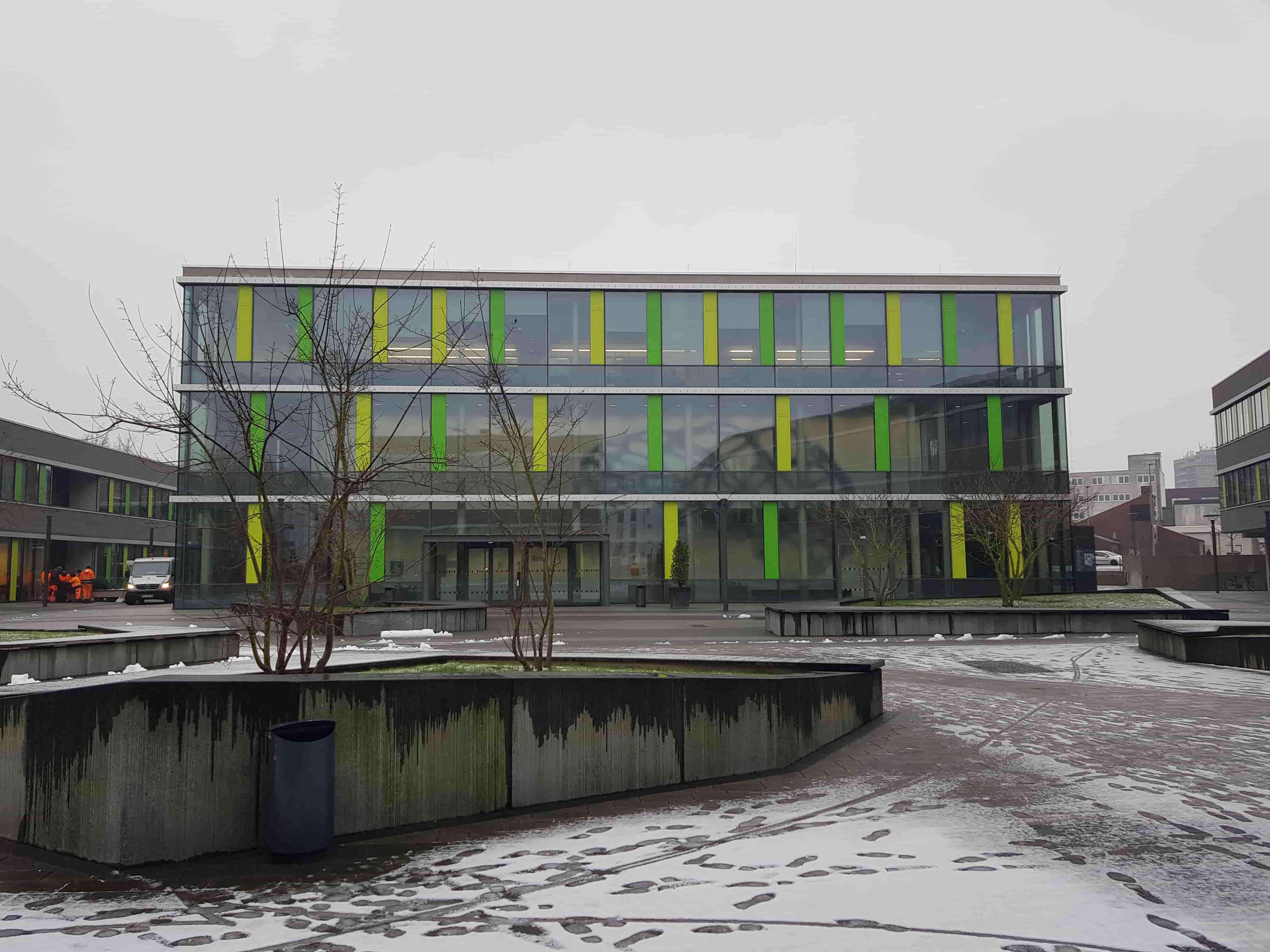
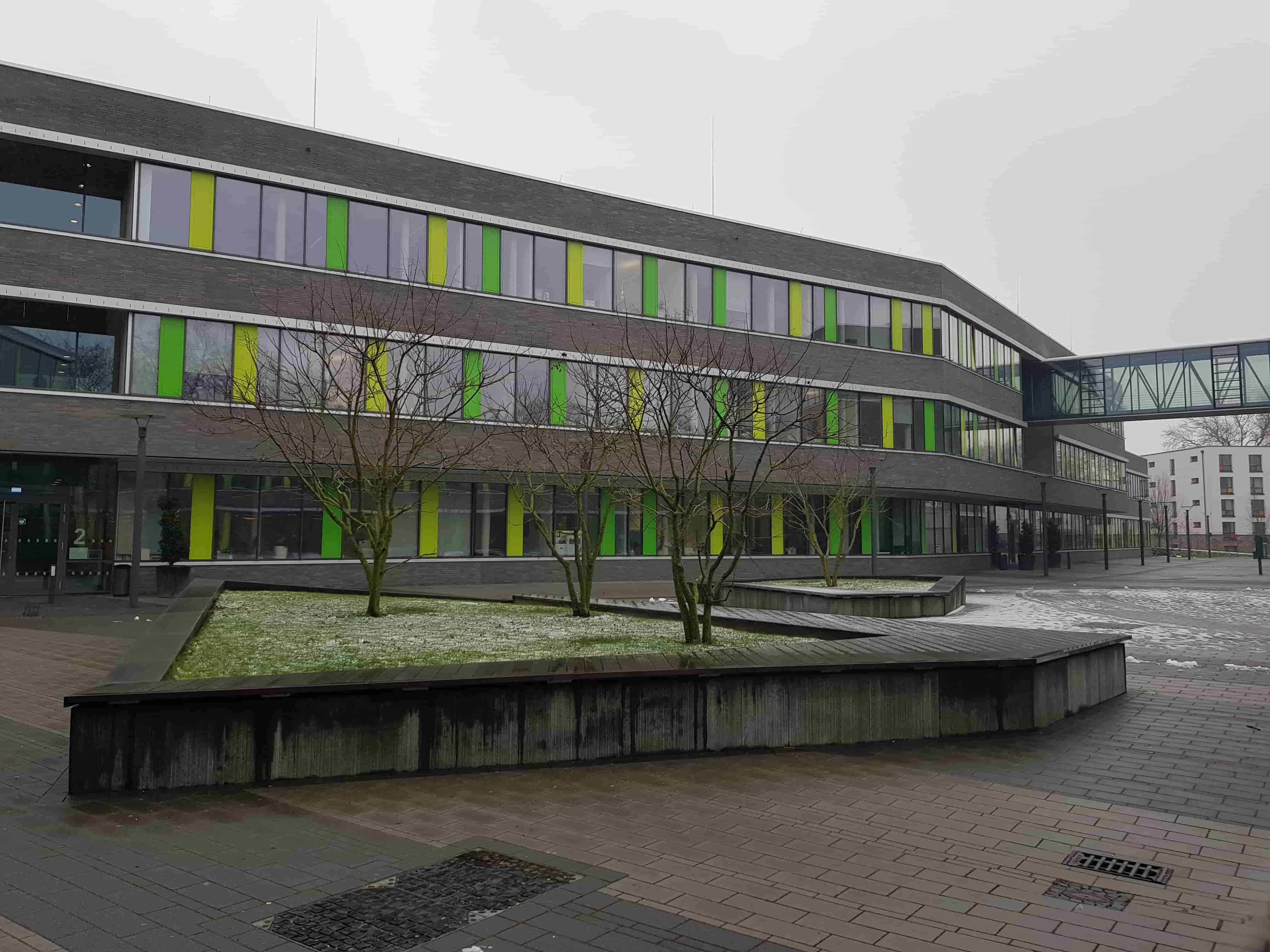
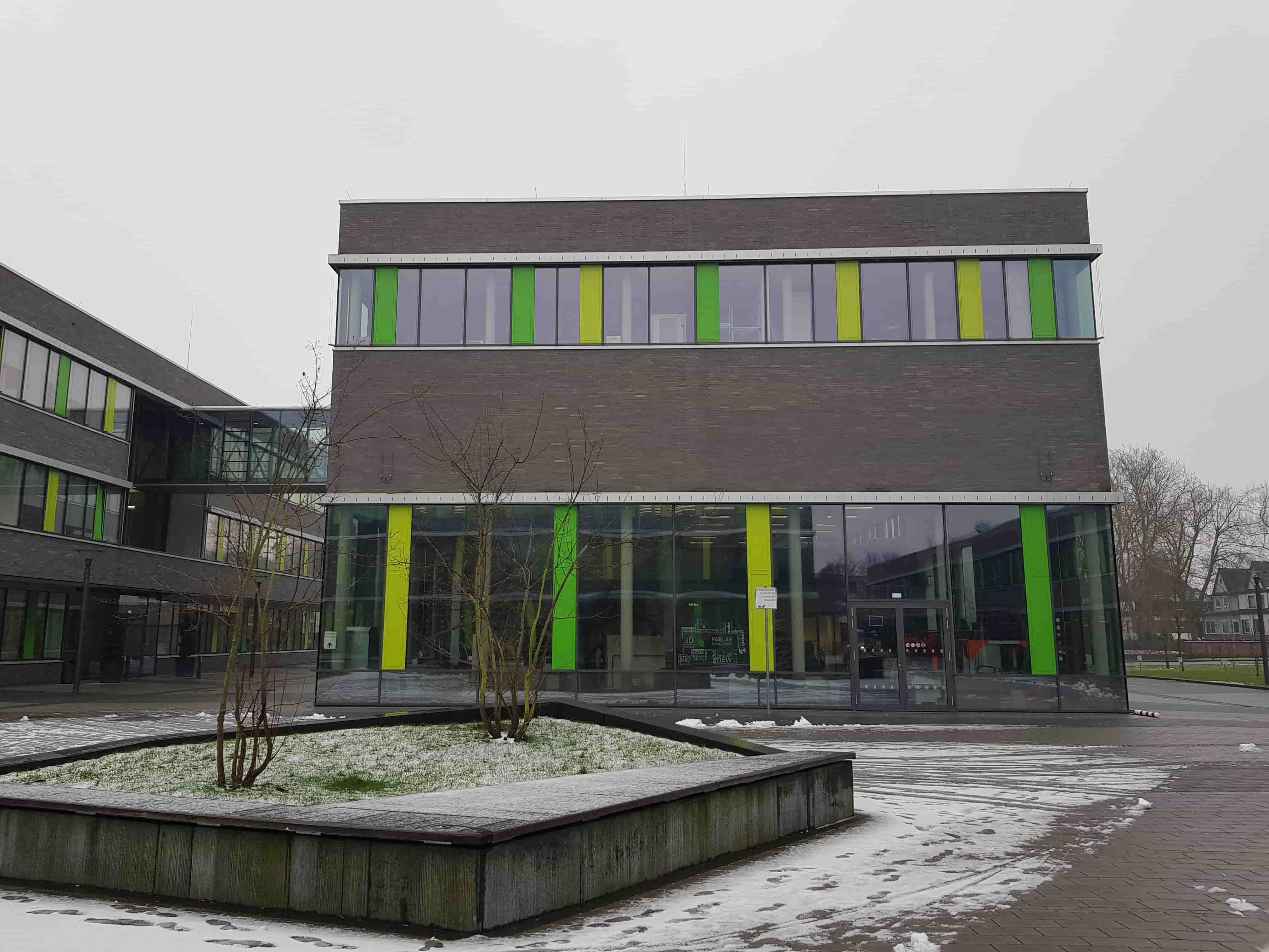
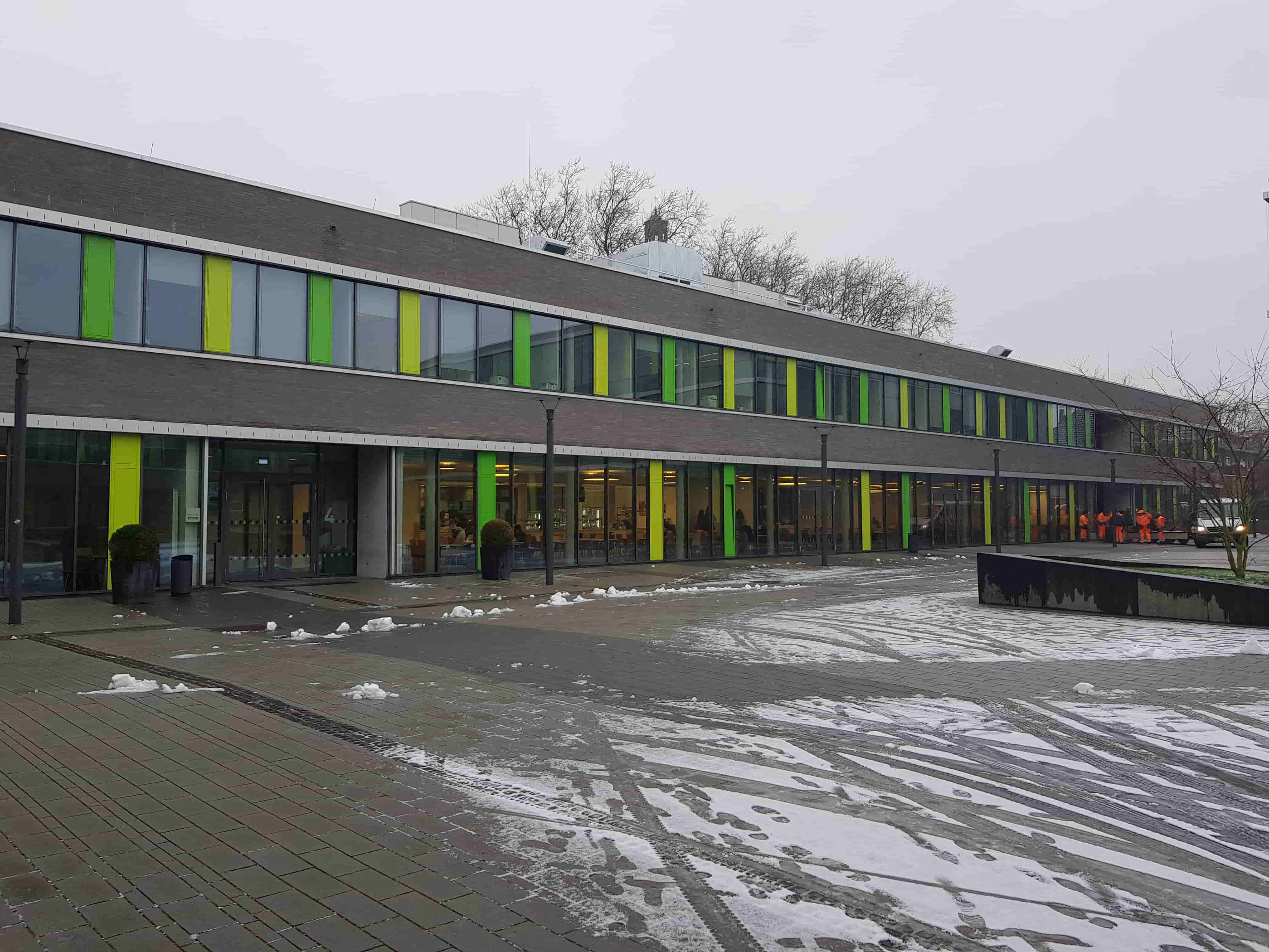
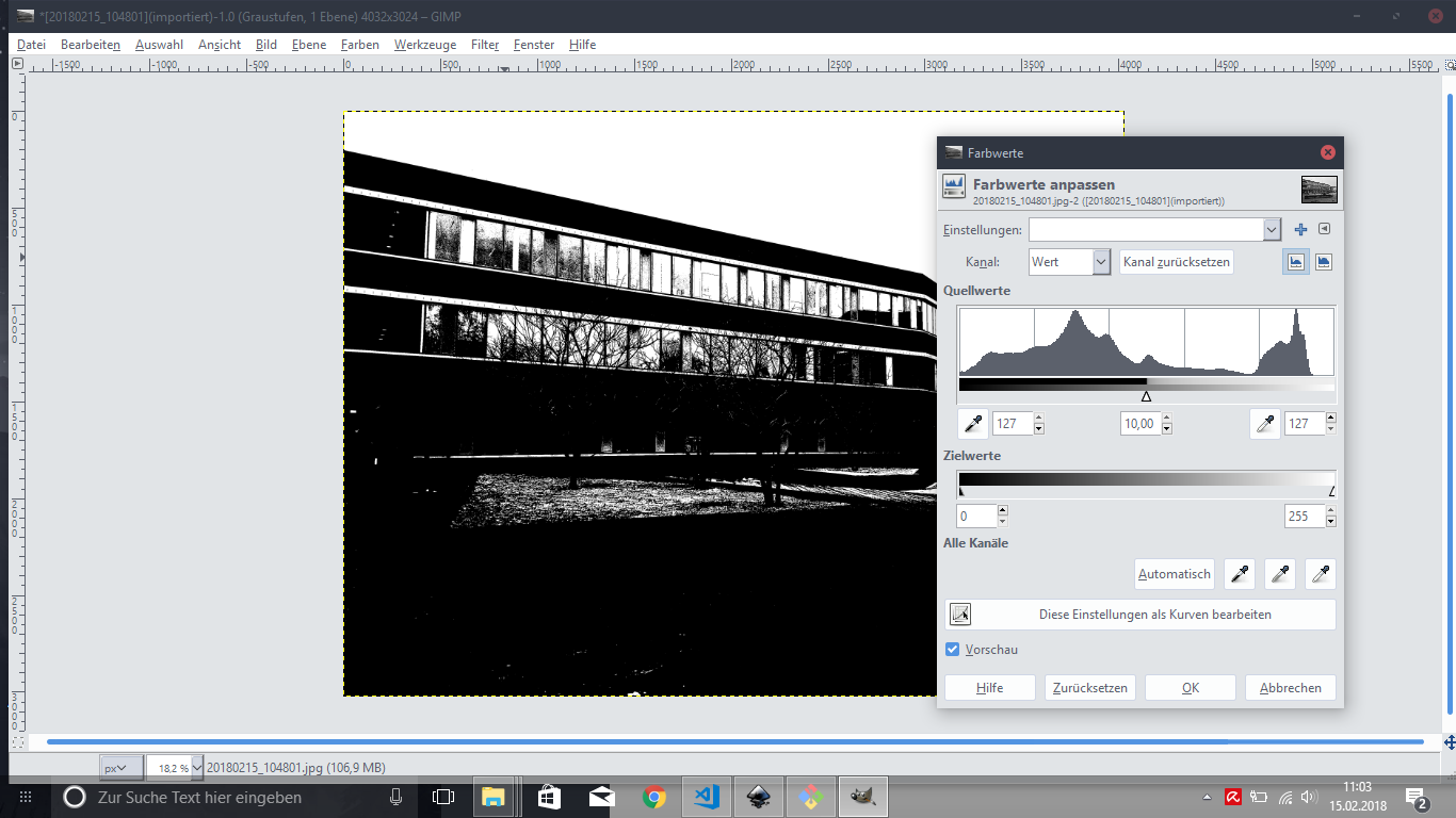
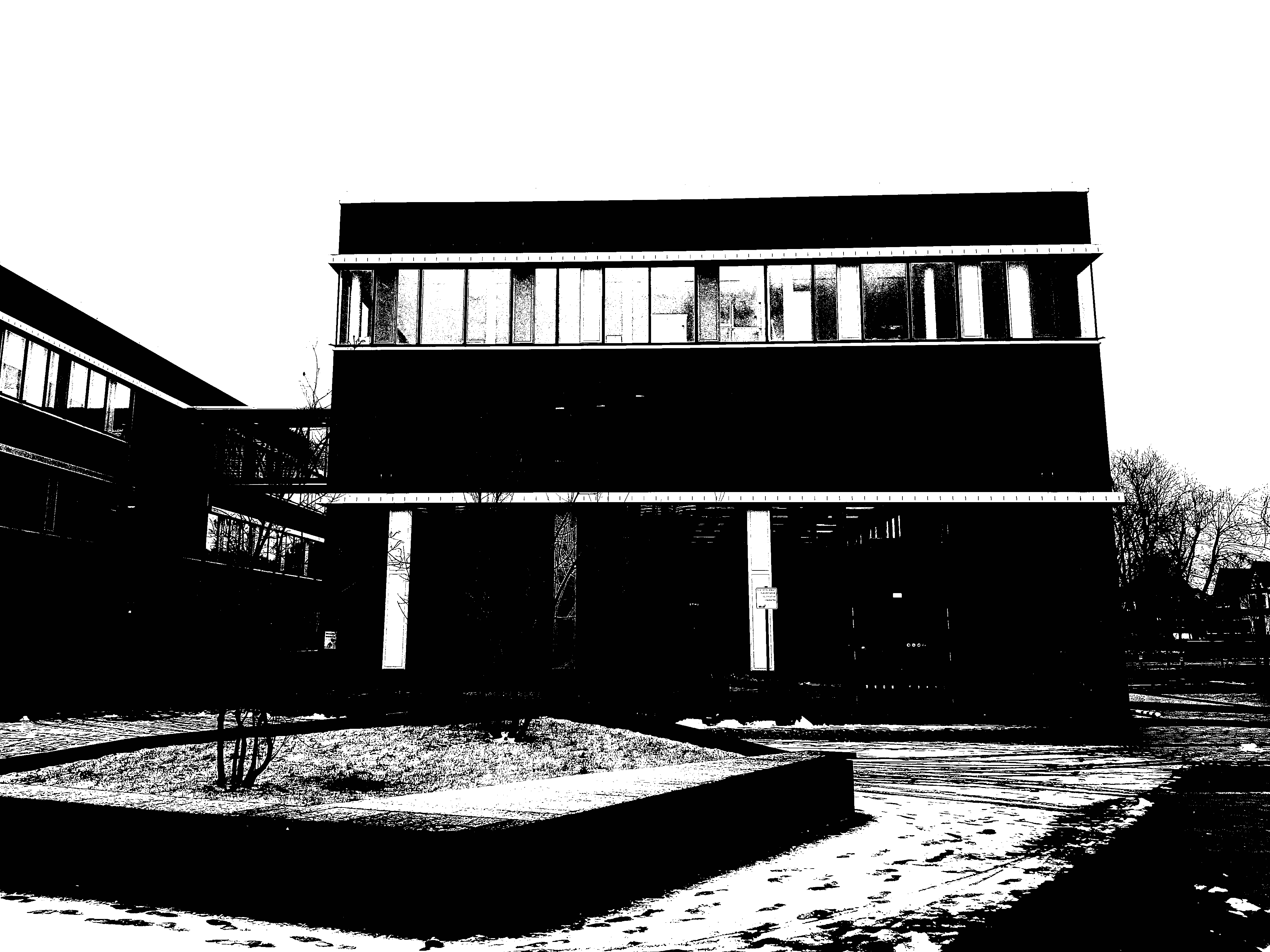
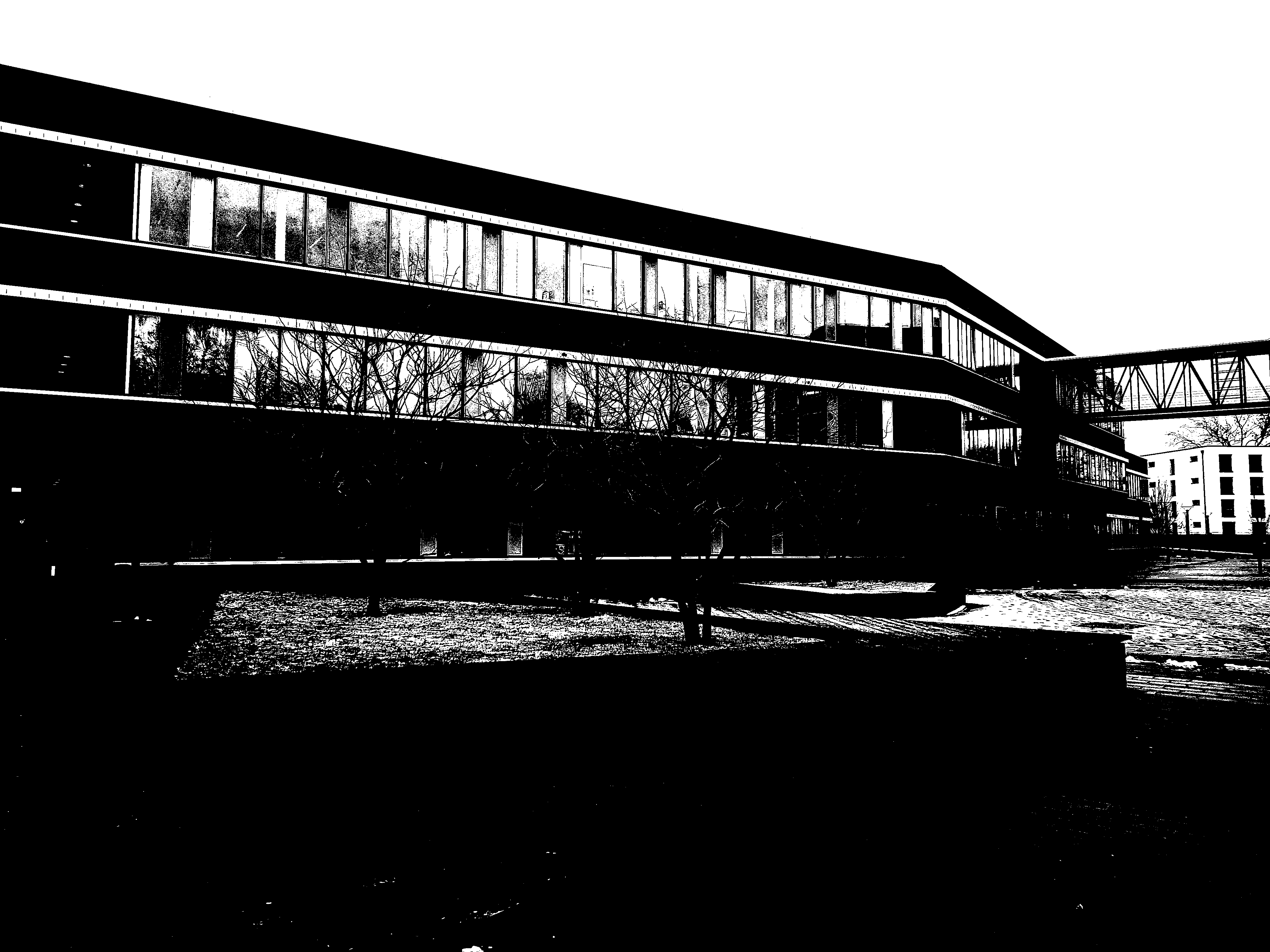
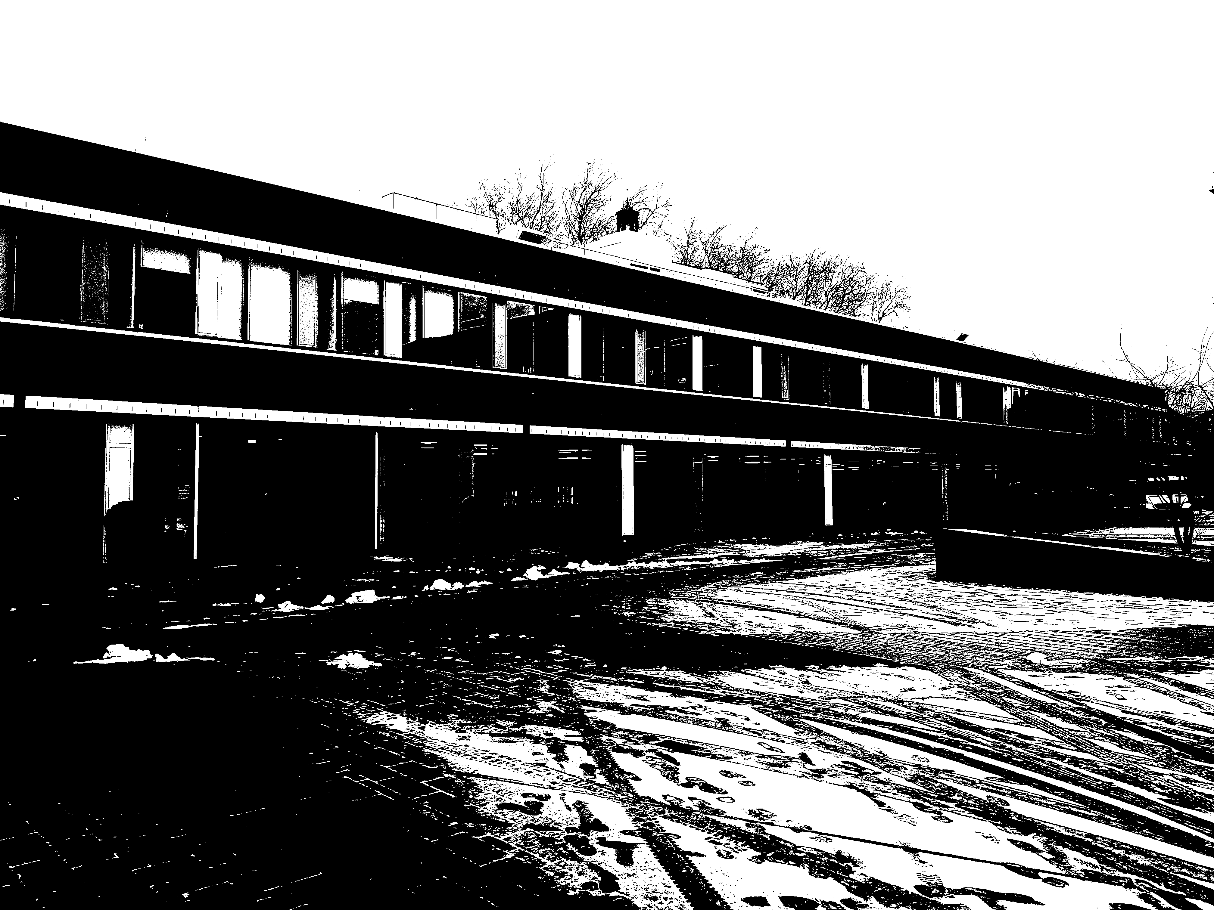
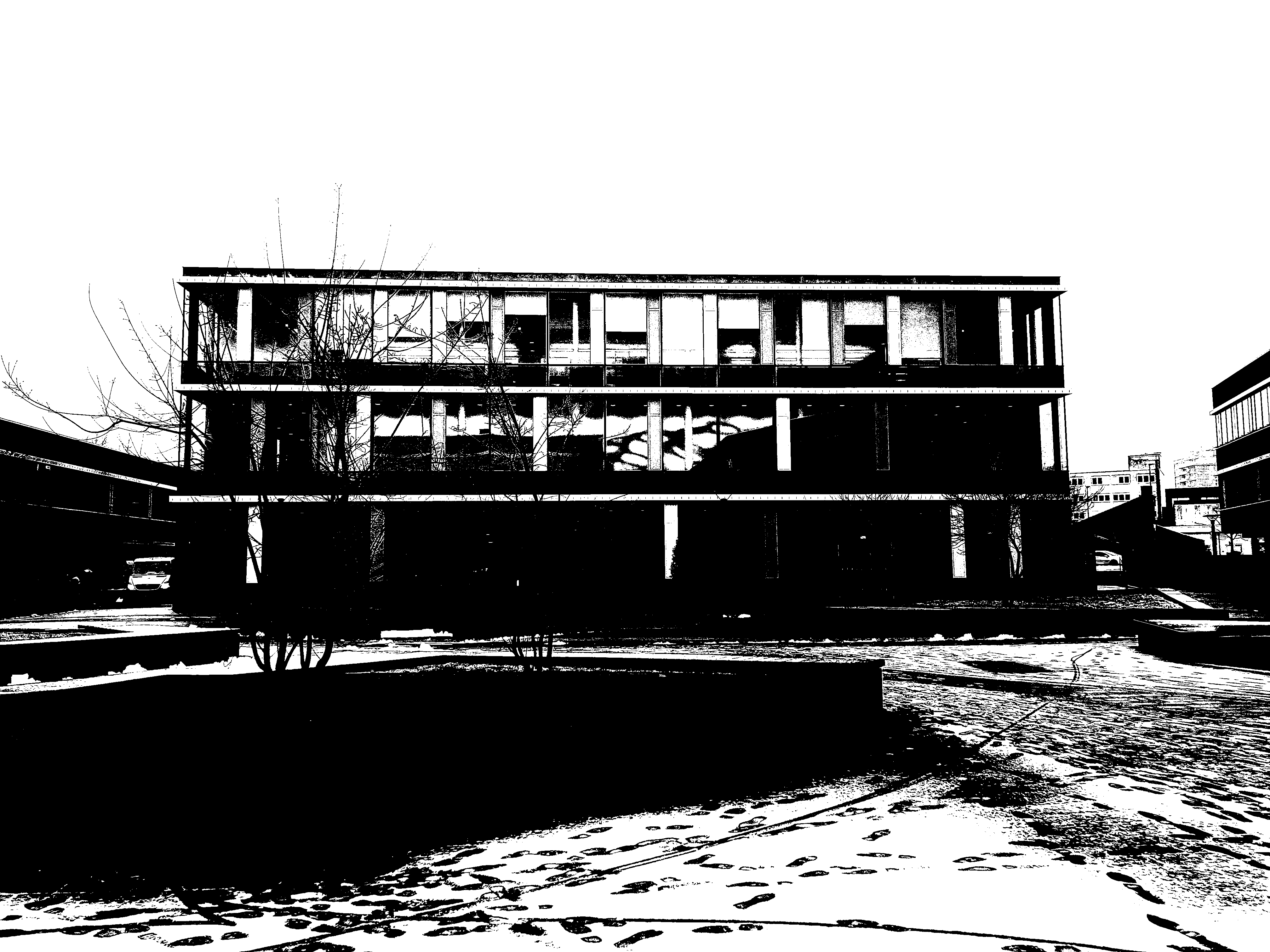
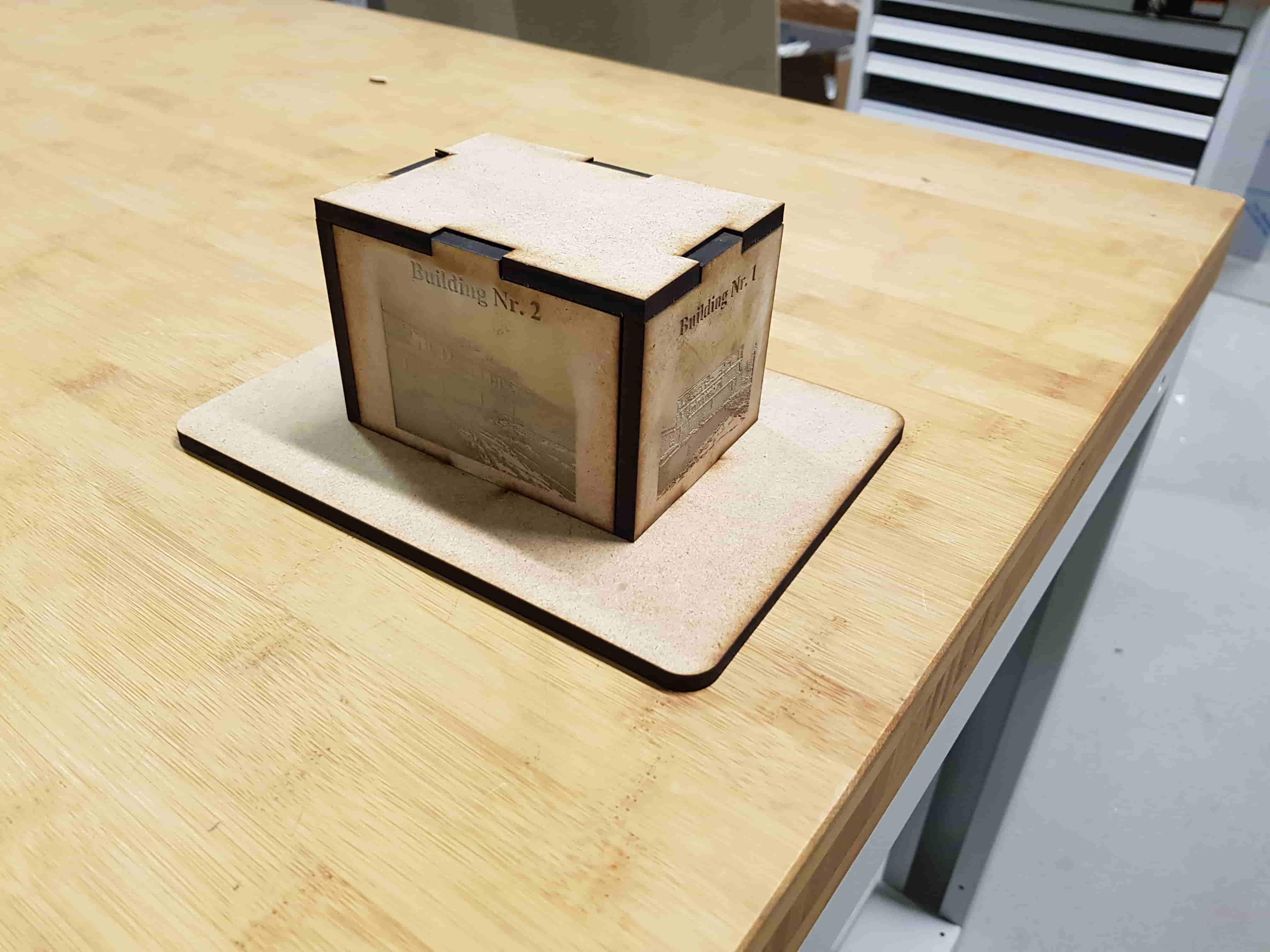
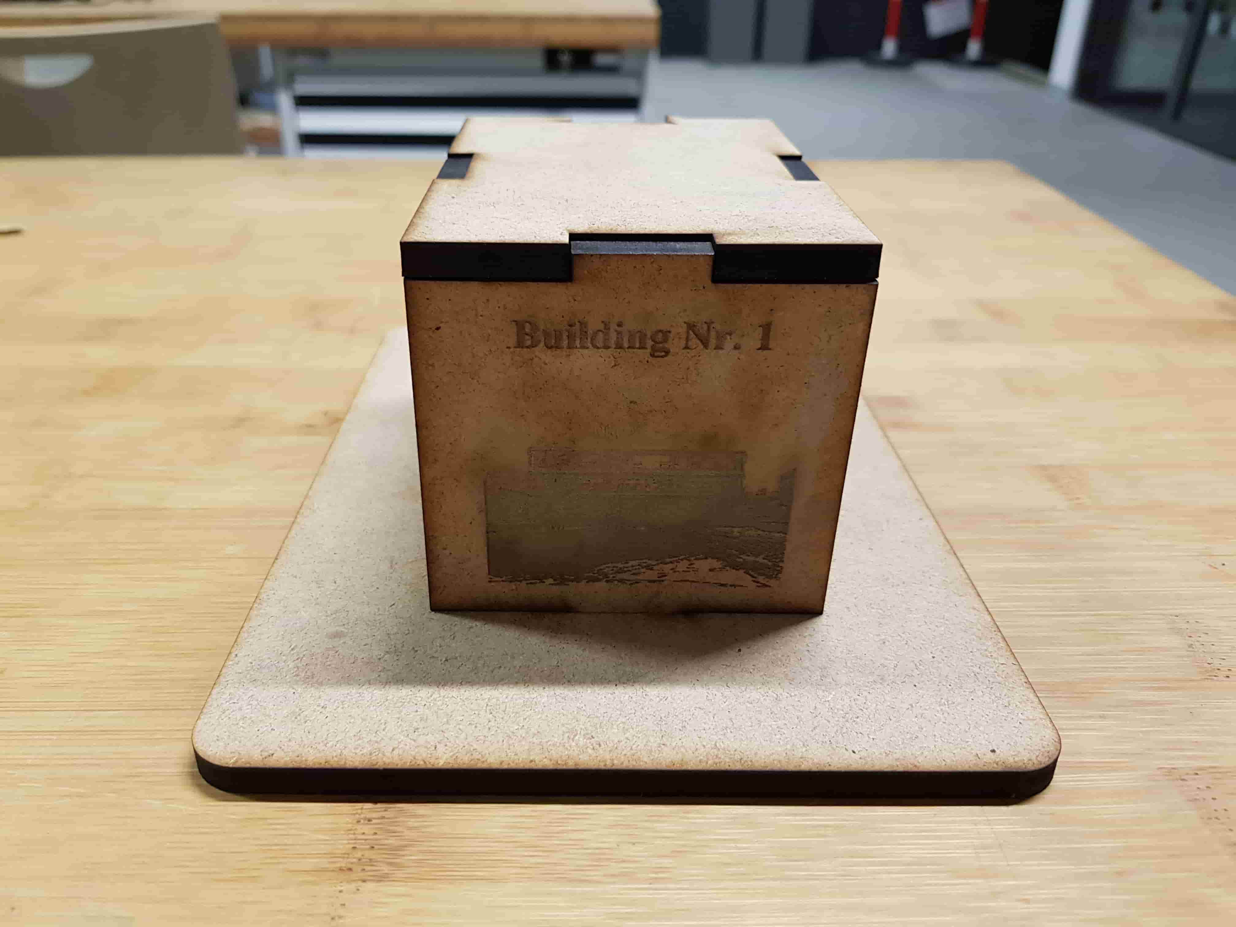
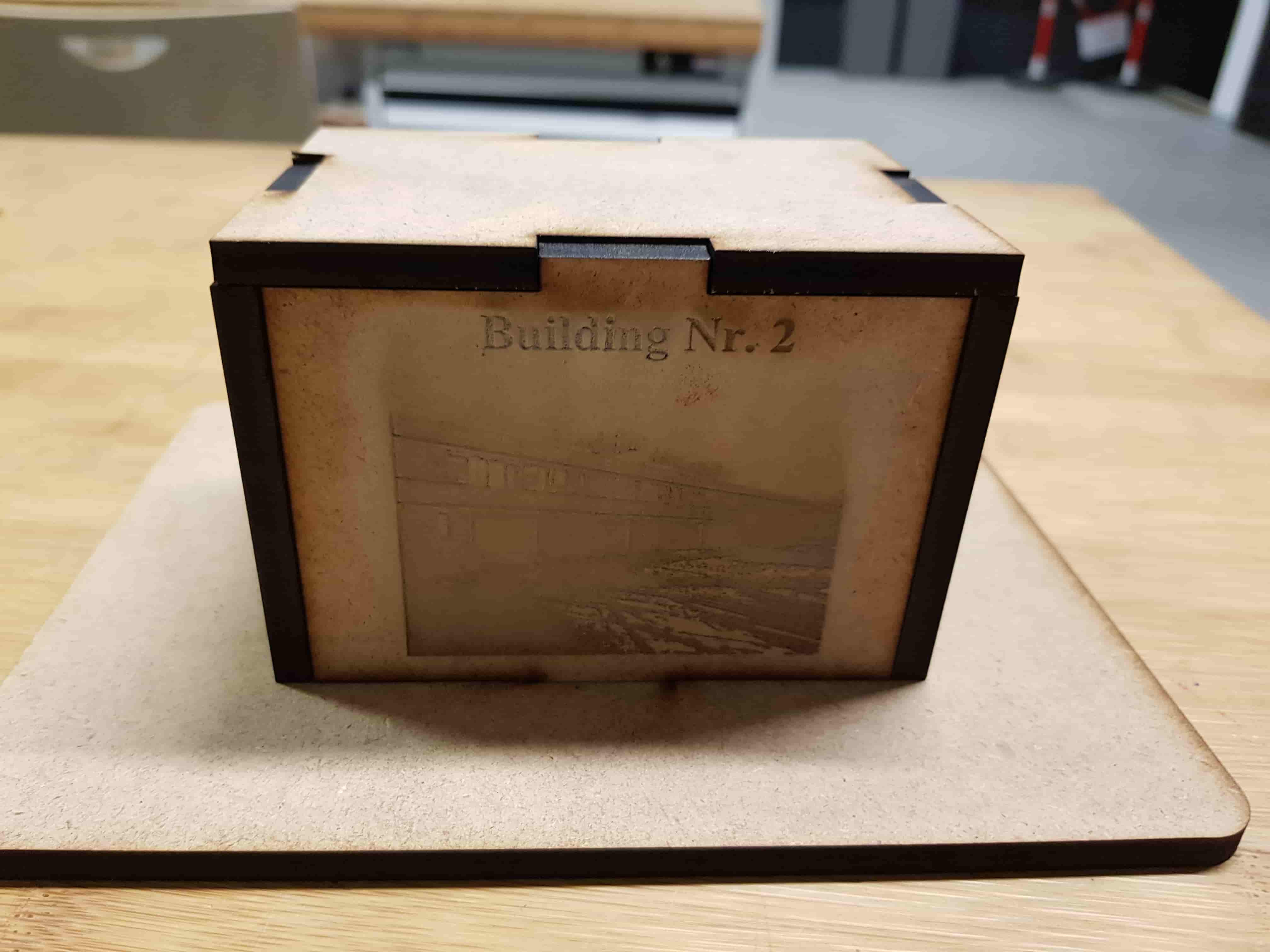
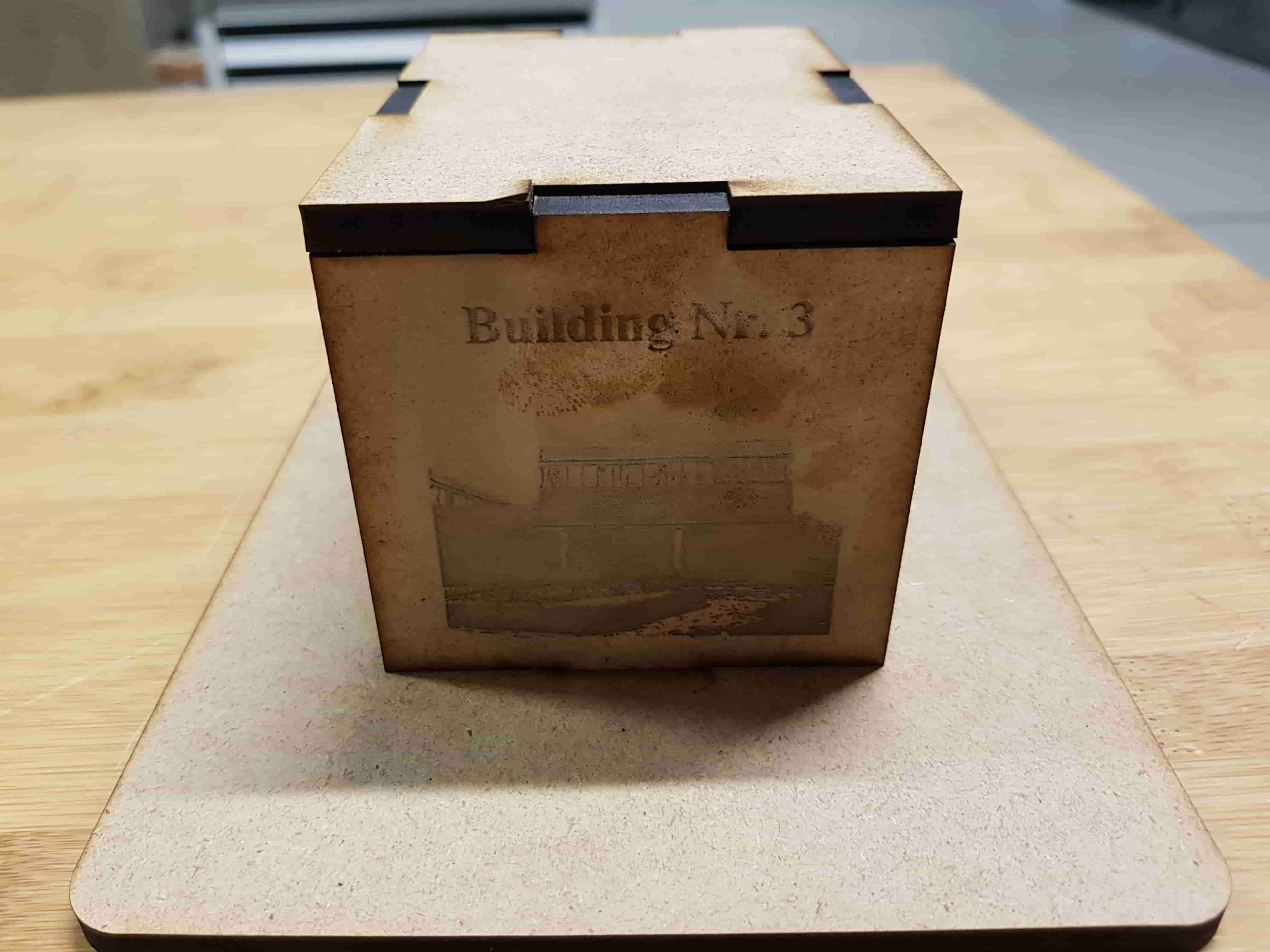
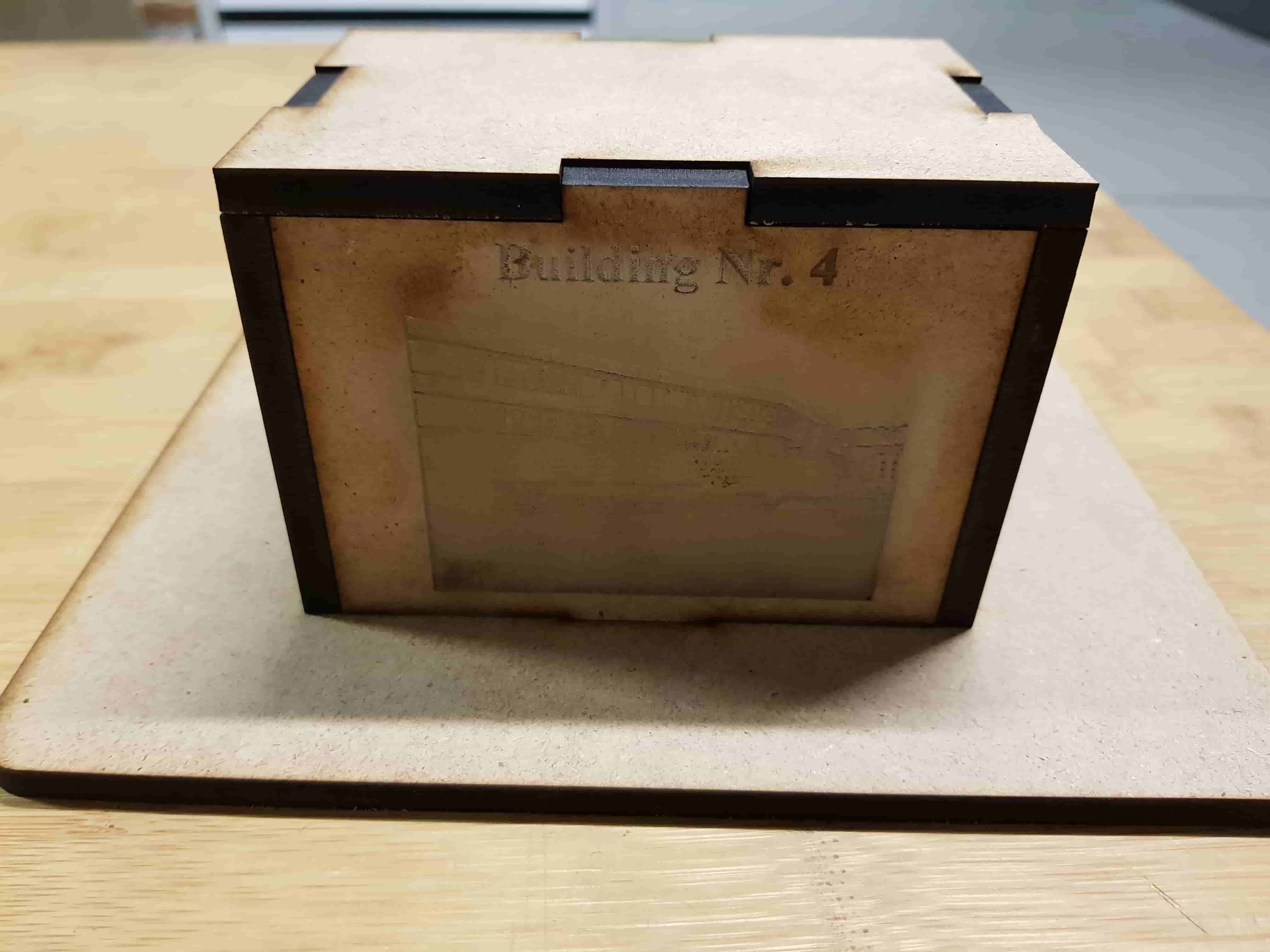
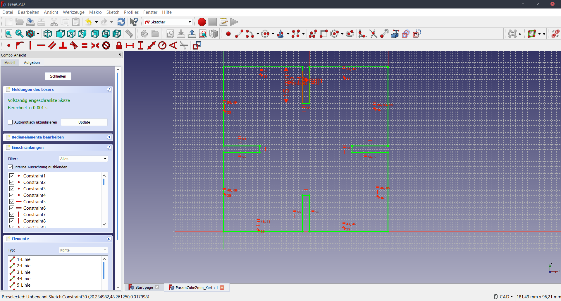
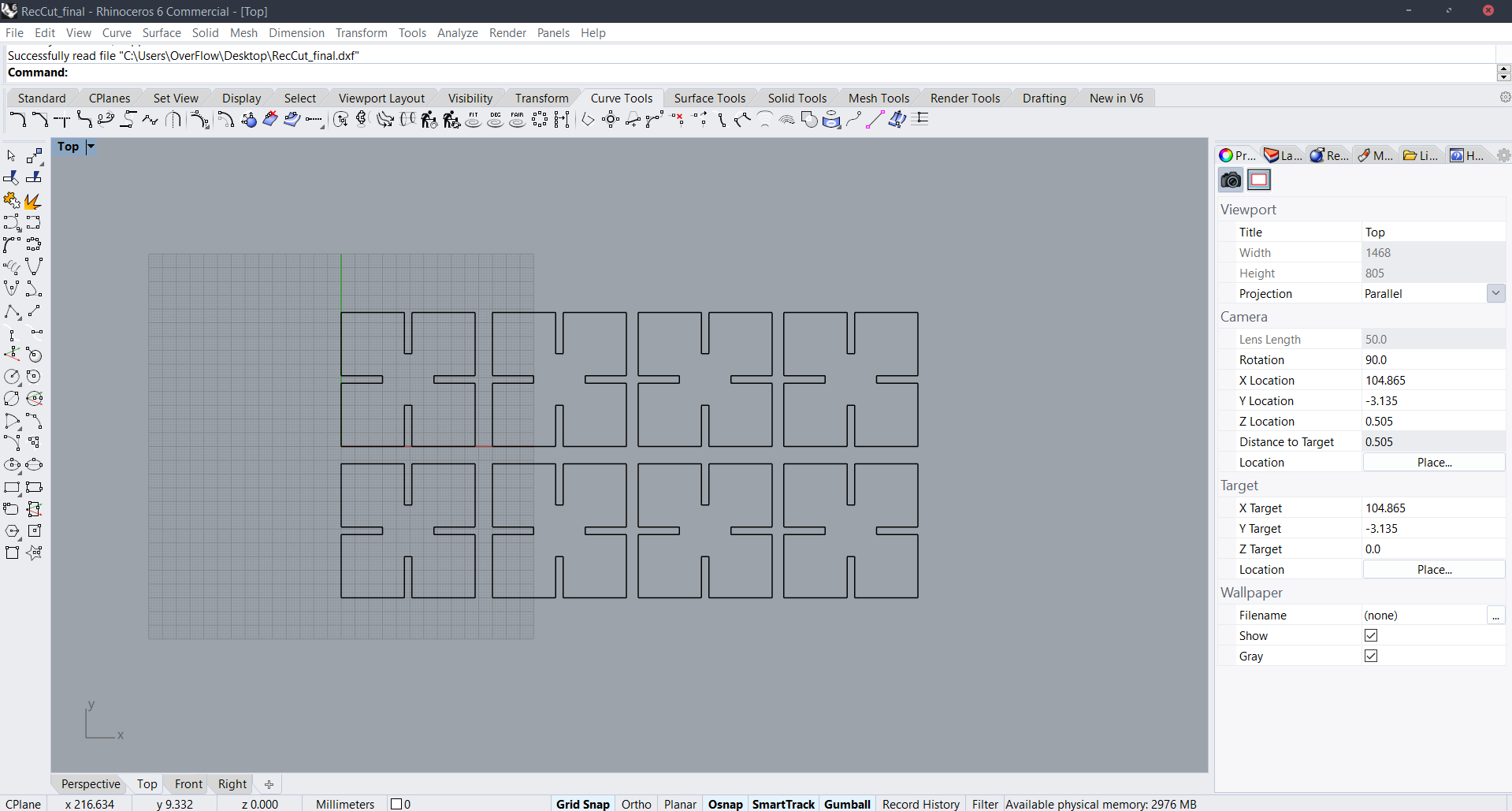
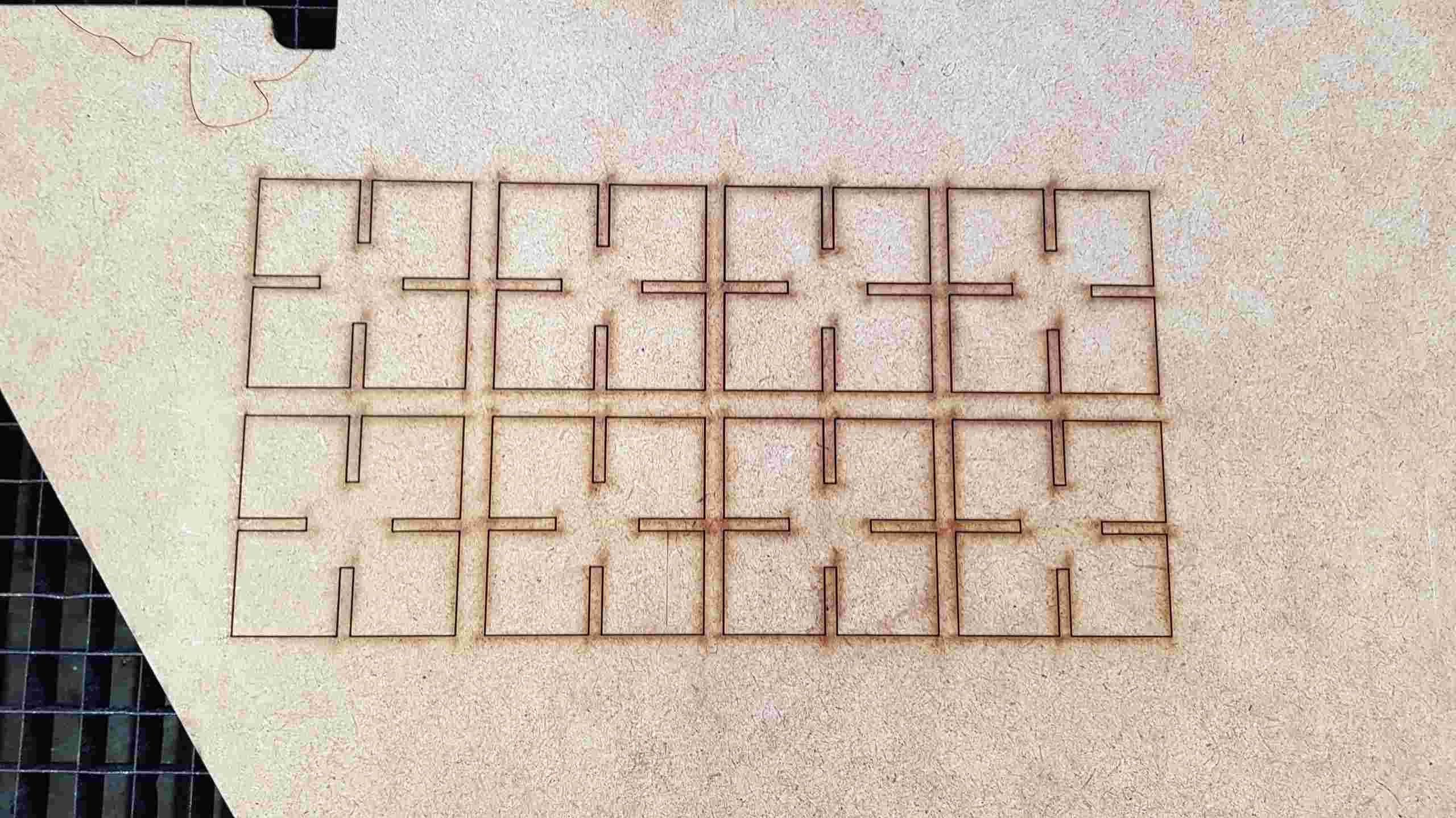
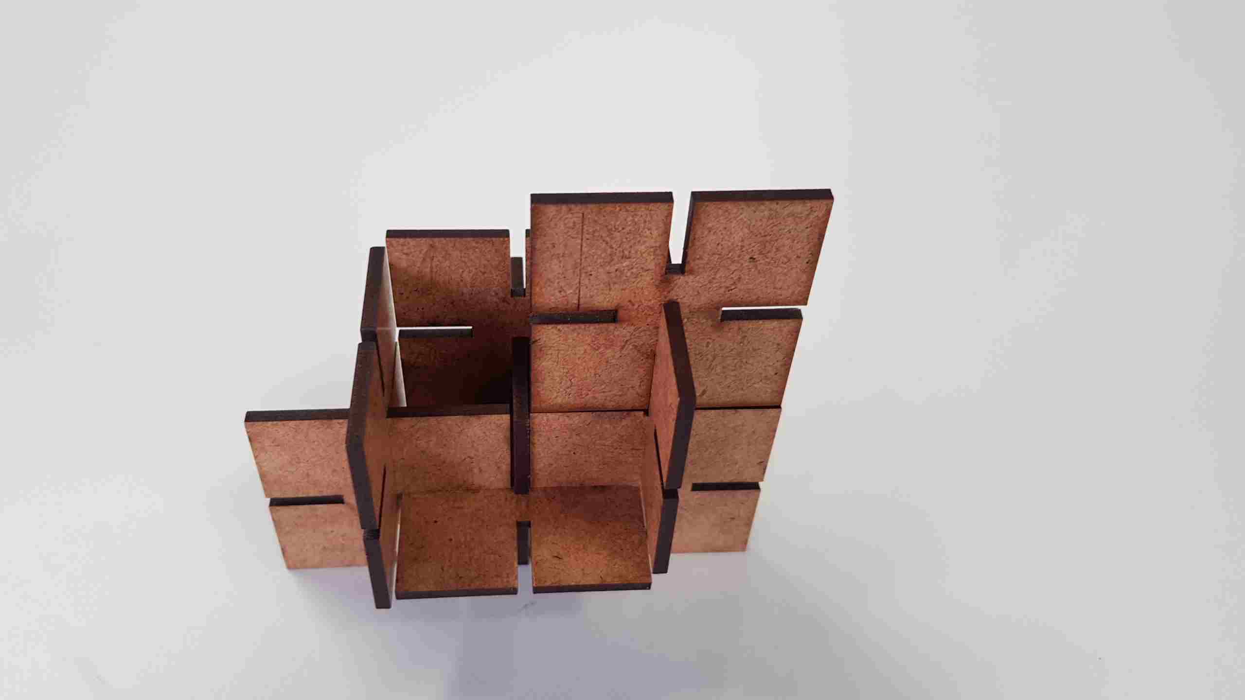
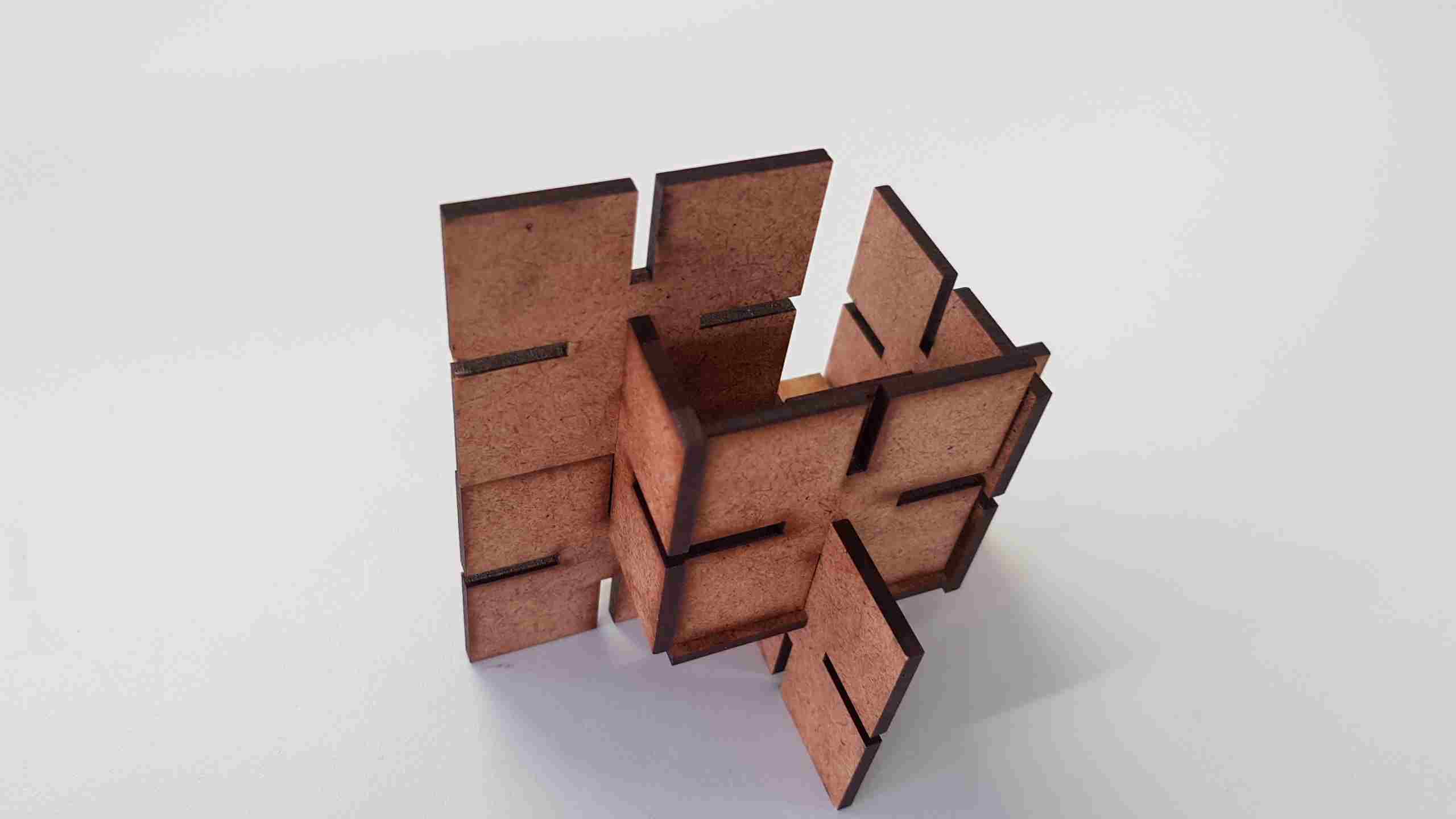
After you have set jog, just press on the joystick, and the machine will remember the position.ImportantWell now, very Important -> turn the 'vacuum cleaner' of the machine on and then you can start the job.Color MappingNow we are ready to send a board as job from a PC to Laser Cutter. But first of all we have to set some paramters for the layers. Again just press Ctrl + P and ist will open you a printing menu. Press 'Properties' Button. You can also set a window and workspace in this menu, just like in a small machine Here are the setting for the Board. We are using Layers with different colors so we have to go to color mapping menu an activate color mapping on the top left corner. On the Picture is the wrong Power for the first 3 Layers for Hatching, I have used 80 %.GoLast step, very Important -> turn the 'vacuum cleaner' of the machine on and then you can start the job. The Display will also show the approx. time for th whole work(it is now a proper time for of the board)Viny CutterSo the another part of the assignment, was to learn how to oprate with the viny cutter. Therefore we had to choose something of meake it our design and cut it out. I my case, I have choosen not official One Piece logo.ConvertThe image that i have, was not able to be printed, so I had to vectorize it, le in the picture before. I have converted it online, with this site:https://jpgtodxf.online/ But it was not enough.RemovingAs you can see the dfx file had some lines that I had to removeFinal DFXSo now we have a Final DFX, that we can use to cut with vinyl cutter.SilhouetteSilhouette is the programm, that comes with the installation disk of vinyl cutter. To wark on it, we have to set some (optimal)properties, that you can see on the picture below.JoBOkay now we can start the job with "Ctrl + L". I will not explain, how to connect the vinyl cutter and prepair the paper to use, it is rather simple.DoneI had some trouble after the cutting. You should be really carefull, while removing it, you can stretch it. And it will not fit properly as the whole sticker. I my case, I had to cut two times.Group AssignmentOkay this is a Gropu Assignment. We decided to make some kind of library, for the Lasercutter. At the following image, that you can see below, is a muster of one page. It has infomation of opm. cutting settings and engraving possibilities. We have given different RGB values for each cube in order to map the to the cutting settings in the future.Color MappingFirstly we wanted to make 10% difference for the steps, but then we have found, that Epilog color mapping tool, can not handle mre than 16 colors. So we nade the difference of 25 %. We also nfound that we can save the color mapping and use it again. (.DAT)KERFThe Datasheet also has the information of the Kerf. Here you can see the layout of the 'Kerf-detector'. The main Idea of it, is to make 10 slices on the bottom part, put them together and compare the lenght of the top.ExamplesHere are Some ExamplesEngraving of ImagesOkay this part is only about the Engraving of images. First of all i have taken 4 pictures of 4 building in our campus.2-nd Building3-rd Building4-th BuildingGIMP & Gray & ContrastThe first thing that we have found as a group experimenting -> in order to have a good engaving of some picture it has to be 1st: Black and White with good contrast. On the Image bleow you can see how to do this.AfterThis is how the image looks like after the modification.2-nd Building3-rd Building4-th BuildingCaseThan I have made a Case for itDoneThis is how it looks like.1-st Building "Engraved"2-nd Building "Engraved"3-rd Building "Engraved"4-th Building "Engraved"4-th Building "Engraved"Parametic DesignI have also made some simple design for the parametric part.For this part of the assigment I have used FreeCad, because It's opensource Software. Well I wanted to make something that you can assamble it in a different ways. Actually you have got only one part that you can copy and paste. So the complexity depends on how many part you have got and how you stick them together. Well if you want to have a parametric design, and to change something in it you have to download a FreeCad file an open it in th same program. The .dxf file is not parametric You can see my design below. The following steps have been done, to make the parametric design in FreeCaD 1.Open the Sketch workspace 2. Create a new Sketch 3. Draw the lines 4. Apply the constraints, for my example 3 constraints of length and all the others are the equal constraints.I have exported it as .dxf an imported in Rhino. I also made some copies, to stick them together.Here is the view after the Cut. Here I want to mention 1 thing. I have calculated a Kerf for 2mm MDF(0.135mm for each slice) but I have used 3 mm MDF and it fits perfekt -> the whole thing is rigit after joining them. Here is the Final ResultOther side xDDownloadsPawnRockKnightBishopQueenKingBoardOne Piece.DATParametric Design (FreeCad)Parametric Design (.dxf)