Final Project: Process
Final Project Development
- Individual Assignment: Develop a final project that integrates the range of units covered.
My Process (Pixie's Development)
:: June 11, 2018 ::
This post covers the process of developing Pixie. Here are the main components related to the development of Pixie:
A:: Background (Concept, Precedents, Design)
B:: Packaging, Armature Design, and Fabrication
C:: Screen Design and Fabrication
D:: Electronics (Boards, Programming)
E:: Final Assembly, Questions, Implications, and Future Iterations
F:: BOM (Bill of Materials)
G:: Licensing
H:: Design Files
I:: Acknowledgements & References
A:: Background (Concept, Precedents, Design)
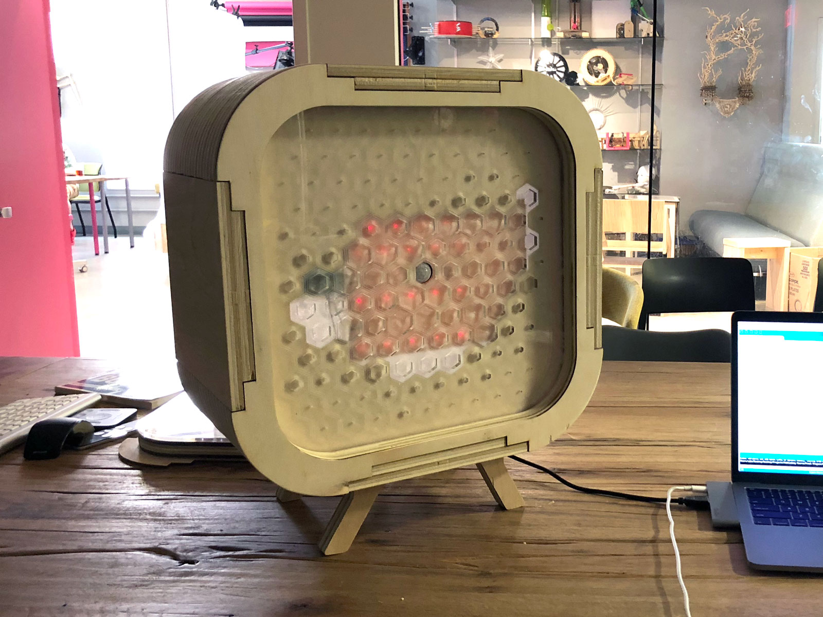
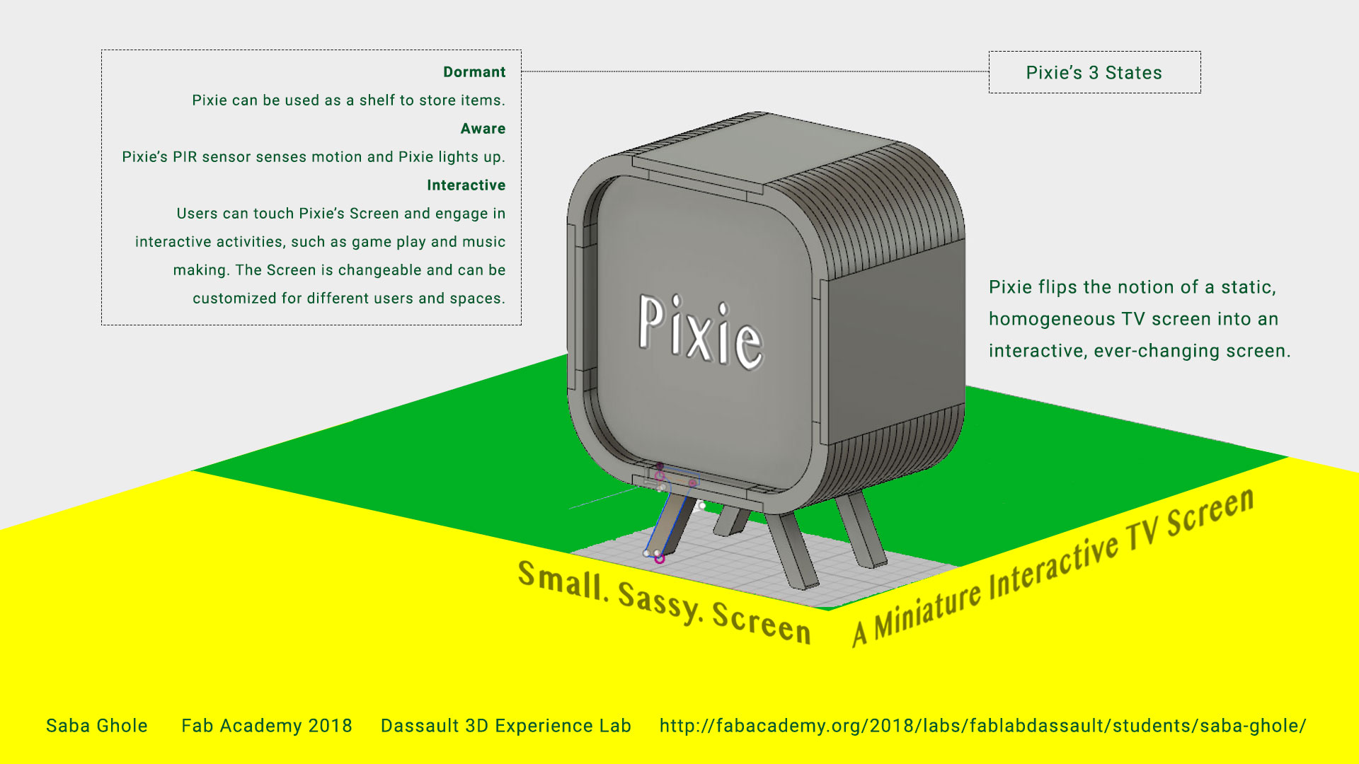
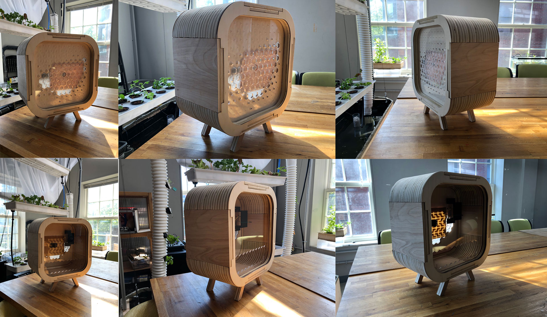
My final project is called Pixie. Pixie is an interactive TV screen.
Now that may sound like an oxymoron, but here’s why it’s not...
I was an architect for many years, and now I’m an educator who still loves design and using design as a process for learning. I started an innovation school 8 years ago, called NuVu Studio, where students work on hands-on projects in a studio-based environment and use the creative process to design solutions to real world problems. Over the years, we’ve seen a growing number of devices in our school, and one of the big challenges for us has been identifying the role of “screens” (computer screens, phones, tablets, or TVs) in our studio and how students and educators should engage with them. Screens can be a tool for students to develop their ideas and projects through the use of 3D design software or they can be a highly distracting and addictive gadget that draws them away from their work and adds a roadblock for collaboration. It’s a constant battle between screens and engagement, and the easier, more accessible option tends to win out, leaving screens to prevail.
In this project, I focused on the idea of screens, specifically a TV screen, and their dichotomy of productive and not productive. TVs have been around for decades, and most of the discourse around screens has focused on our digital objects - computer or iphone screens. I wanted to focus on the other screen (the TV screen) that also sucks up a lot of attention and hasn’t changed much over the last 50 years - it’s still a screen that you stare at in which content is displayed (not created), and doesn’t allow for much experimentation and exploration beyond searching for content to absorb.
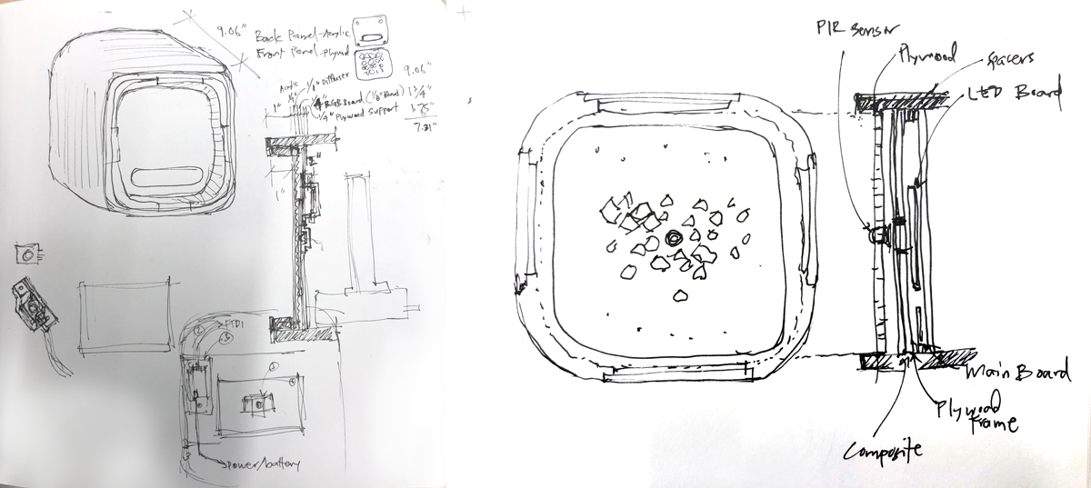
My idea was to flip the notion of a homogeneous, static, and one-directional TV screen into an ever-changing, interactive, and bidirectional screen. Pixie, my final project, engages in this discussion. Pixie has a screen that is forever changing. Unlike a TV in which its qualities remain fixed over time, users can build different screens or facades that can be attached to Pixie’s box frame to create different interactions. Pixie operates in 3 states:
For a deeper background on Pixie, an interactive TV screen, please refer to Exercise 17 - Applications and Implications.
B:: Packaging, Armature Design, and Fabrication
For the design and fabrication of Pixie’s armature, please refer to Exercise 7 - Computered Controlled Machining.
C:: Screen Design and Fabrication
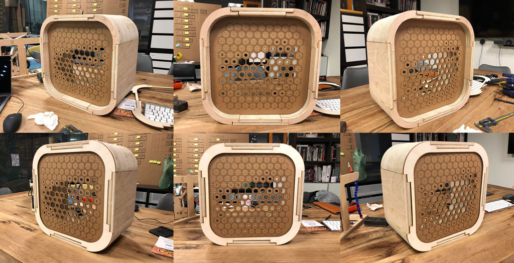
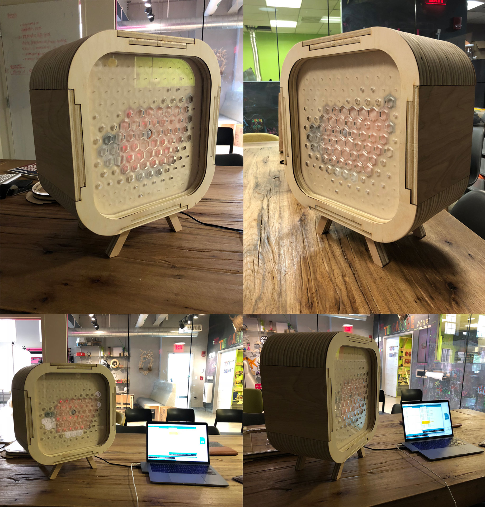
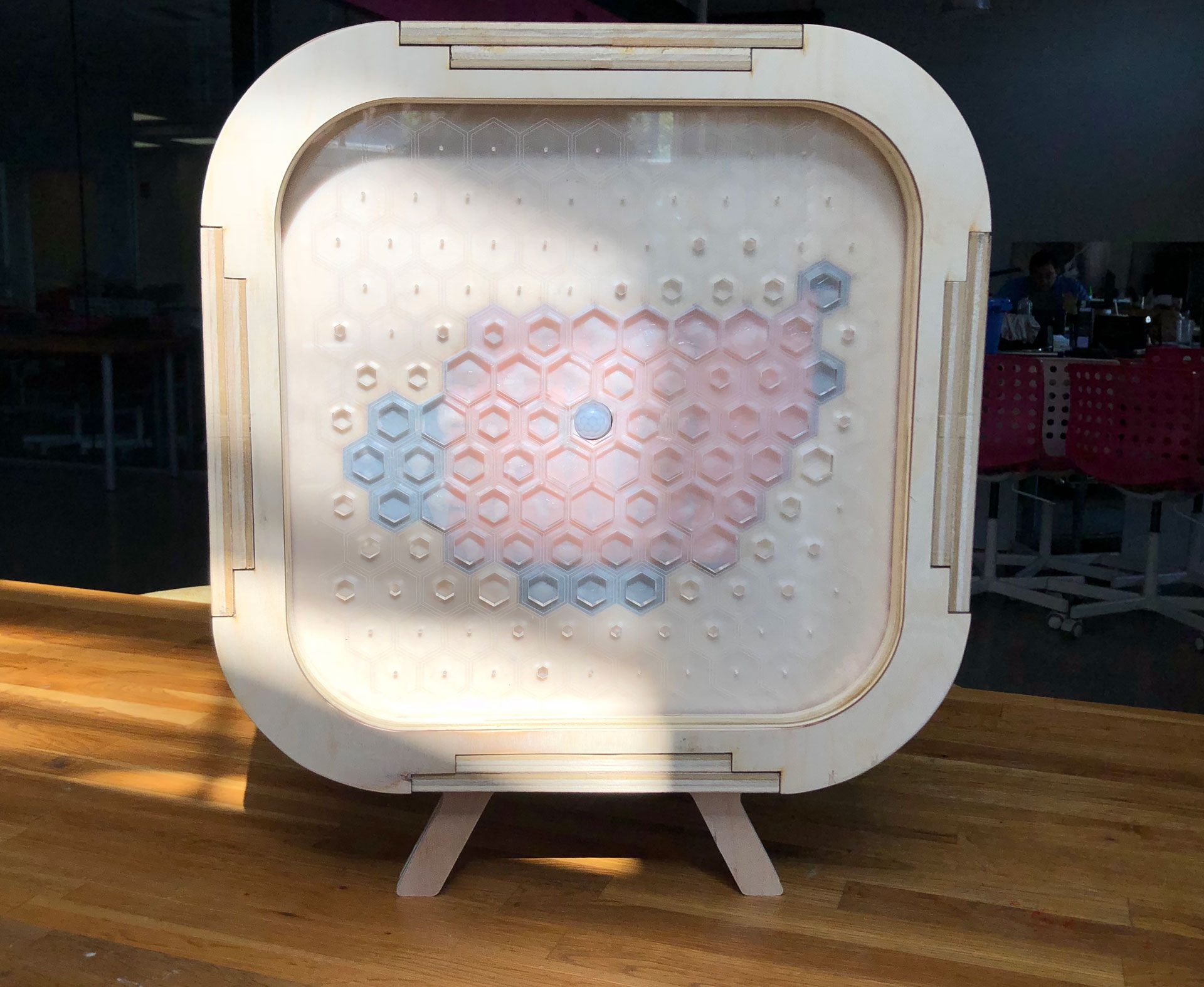
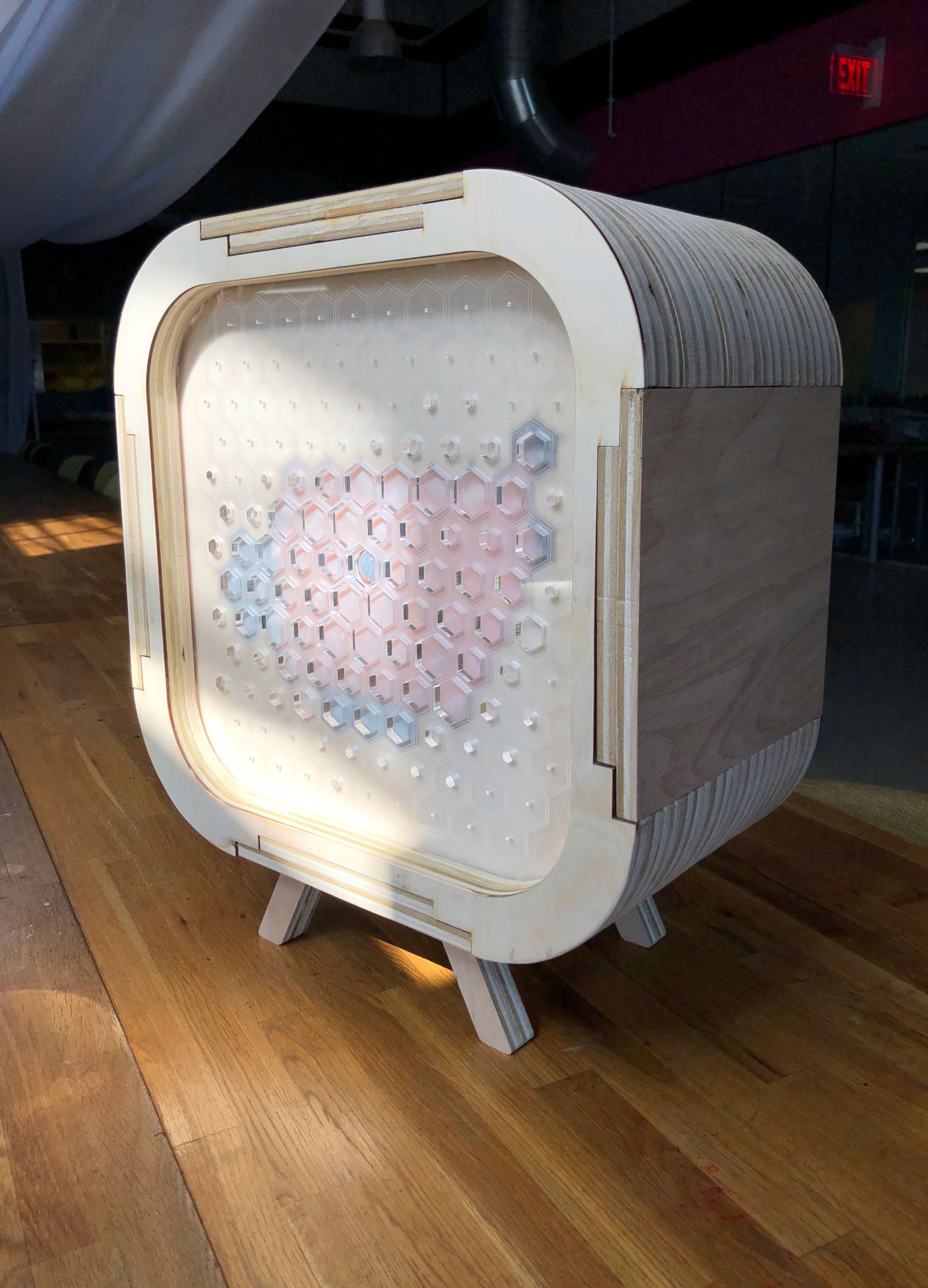
Pixie is designed so that each screen can snap on and off easily through a press fit connection. For my first screen, I created an interactive Halftone Screen. The Halftone Screen is based on the “halftone” technique in which changes in pixel size are used to create different tones and gradations thereby creating unique images.
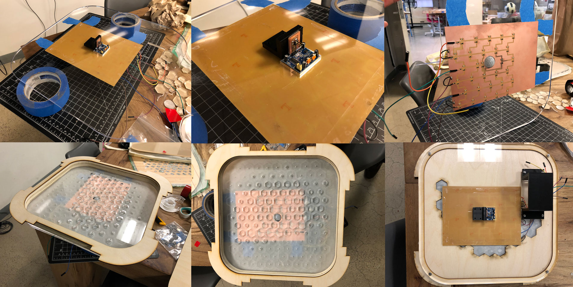
For the Halftone Screen, I created an abstract eye using the halftone process. Typically, we stare at TVs and screens in a singular, one-directional manner, but here the TV looks back bi-directionally. Pixie’s eye looks back at you, observing you and the environment. The iris portion of the eye is lit by a 6x5 matrix of 30 red LEDs that turn on with movement in front of the TV and can be programmed directly to display different images and text.
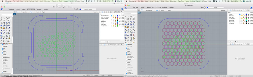
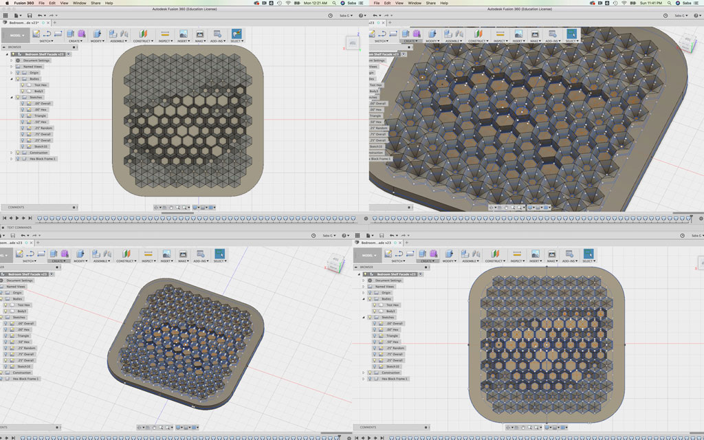
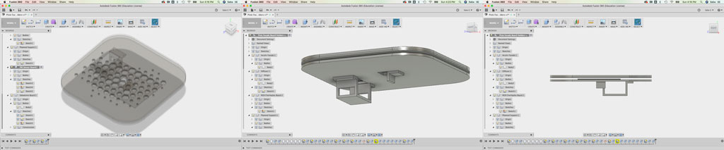
I created quite a few iterations of the Halftone Screen using Fusion 360 and Rhino: a CNC milled plywood version, a layered laser cut plywood version, and finally an acrylic and composite based version. I also used Fusion 360 to model how the different screen layers fit together and also used this model to design 3D printed holders for my boards (Sabaduino Board and PIR Sensor Board). Once I had tested the various screens, I decided on the acrylic-plywood screen and laser cut the pieces.
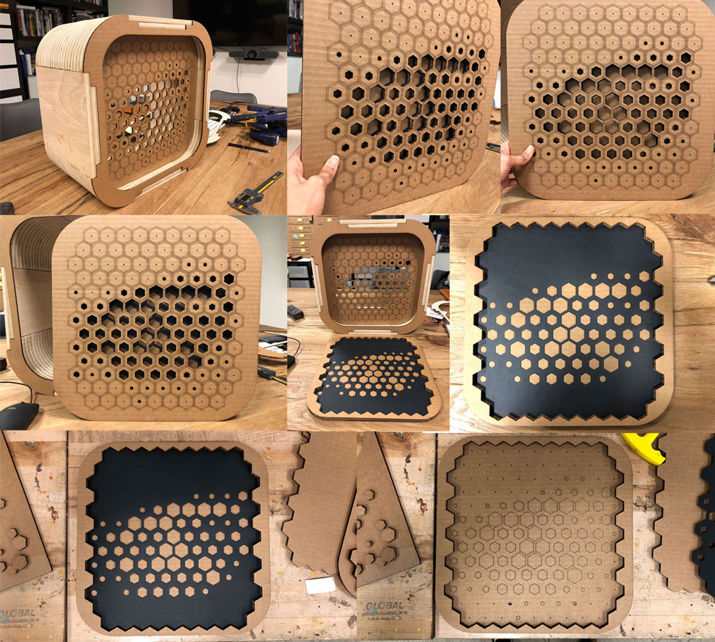
Diffuser
For the design of Pixie’s diffuser, please refer to Exercise 16 - Wildcard Week (Composites).
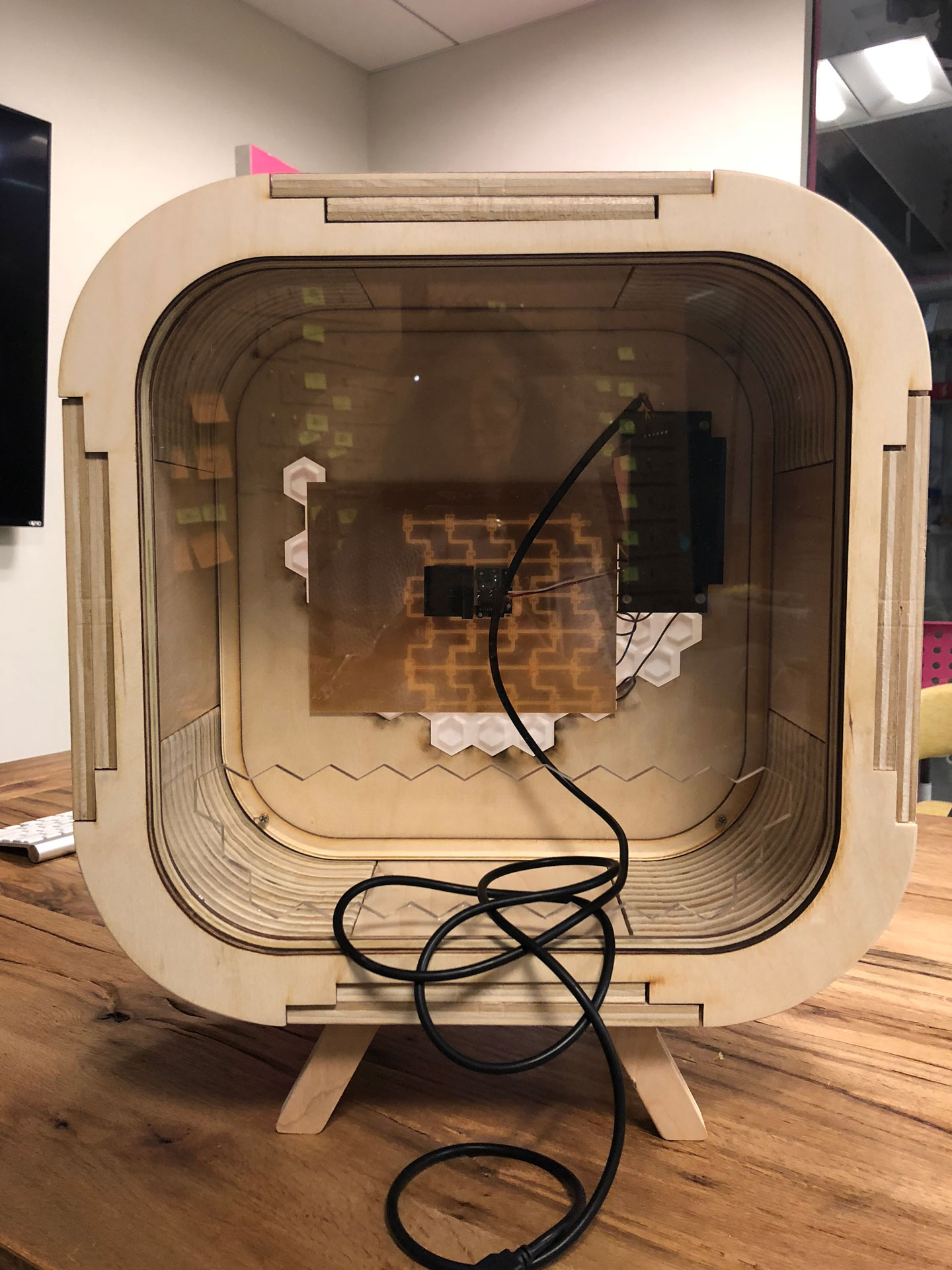
Assembly
I carefully assembled all the pieces of the front Halftone Screen, including the LED Charlieplex Board. I also assembled the back screen, a simpler acrylic facade with an opening for wires.
D:: Electronics (Boards, Programming)
Sabaduino Board
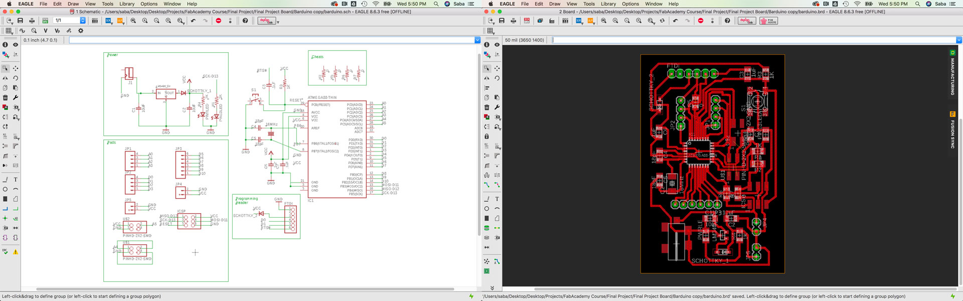
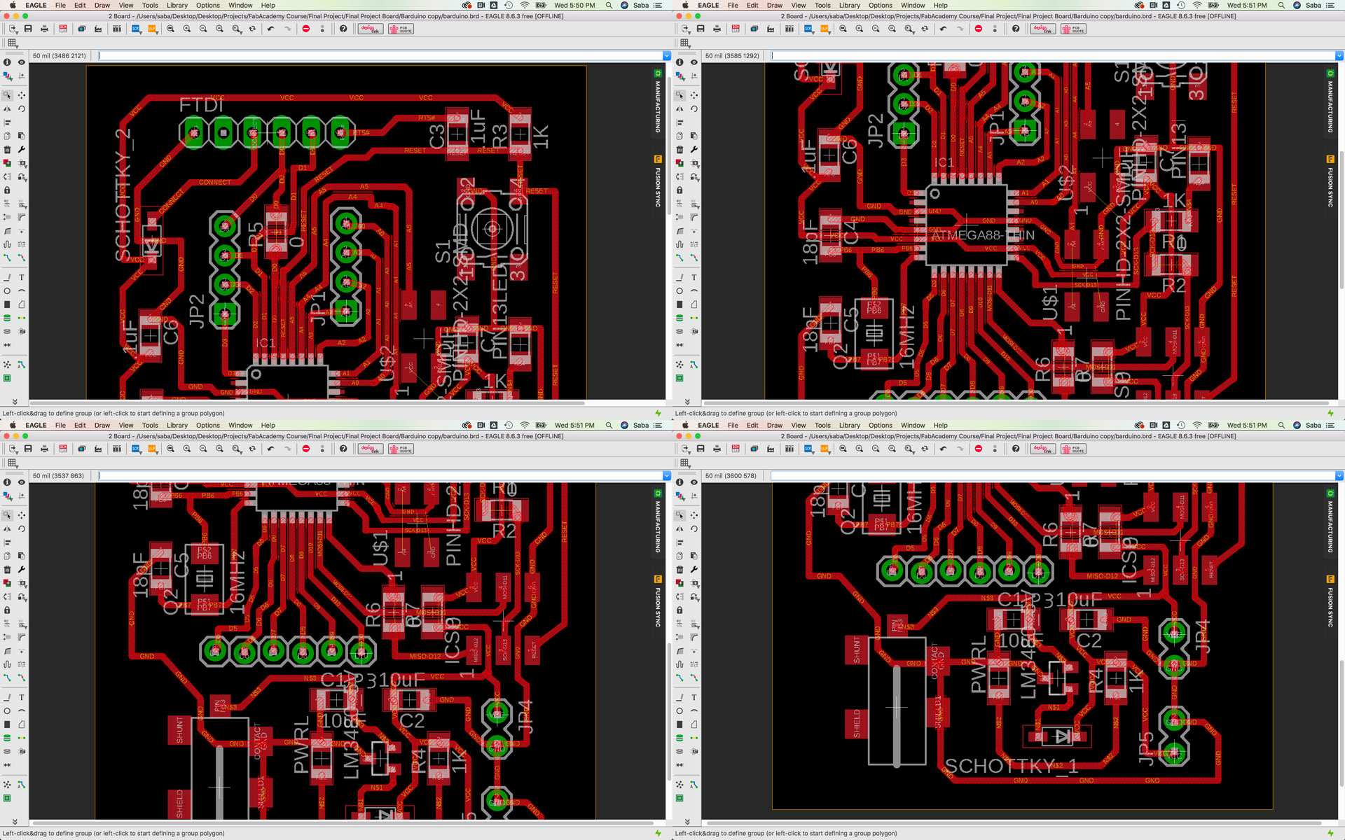
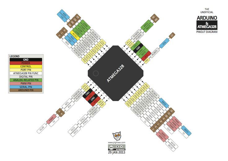
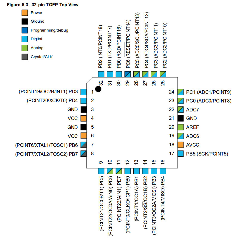
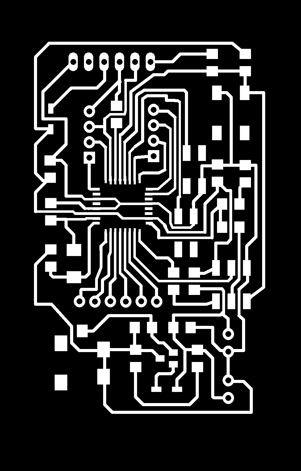
For my main board, I decided to use the ATMega328 microcontroller to allow for more flexibility in terms of inputs and outputs and also more memory for more extensive coding and programming. I based my design off Luciano’s Barduino Board. However, I added more input connectors/headers onto my board for my PIR Sensor and button. My main board is called the “Sabaduino” Board and is very akin to an Arduino board.
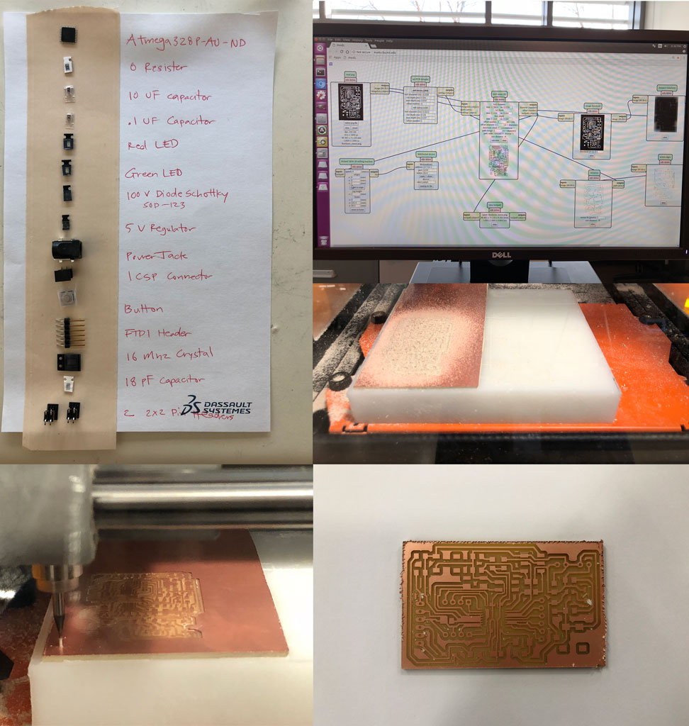
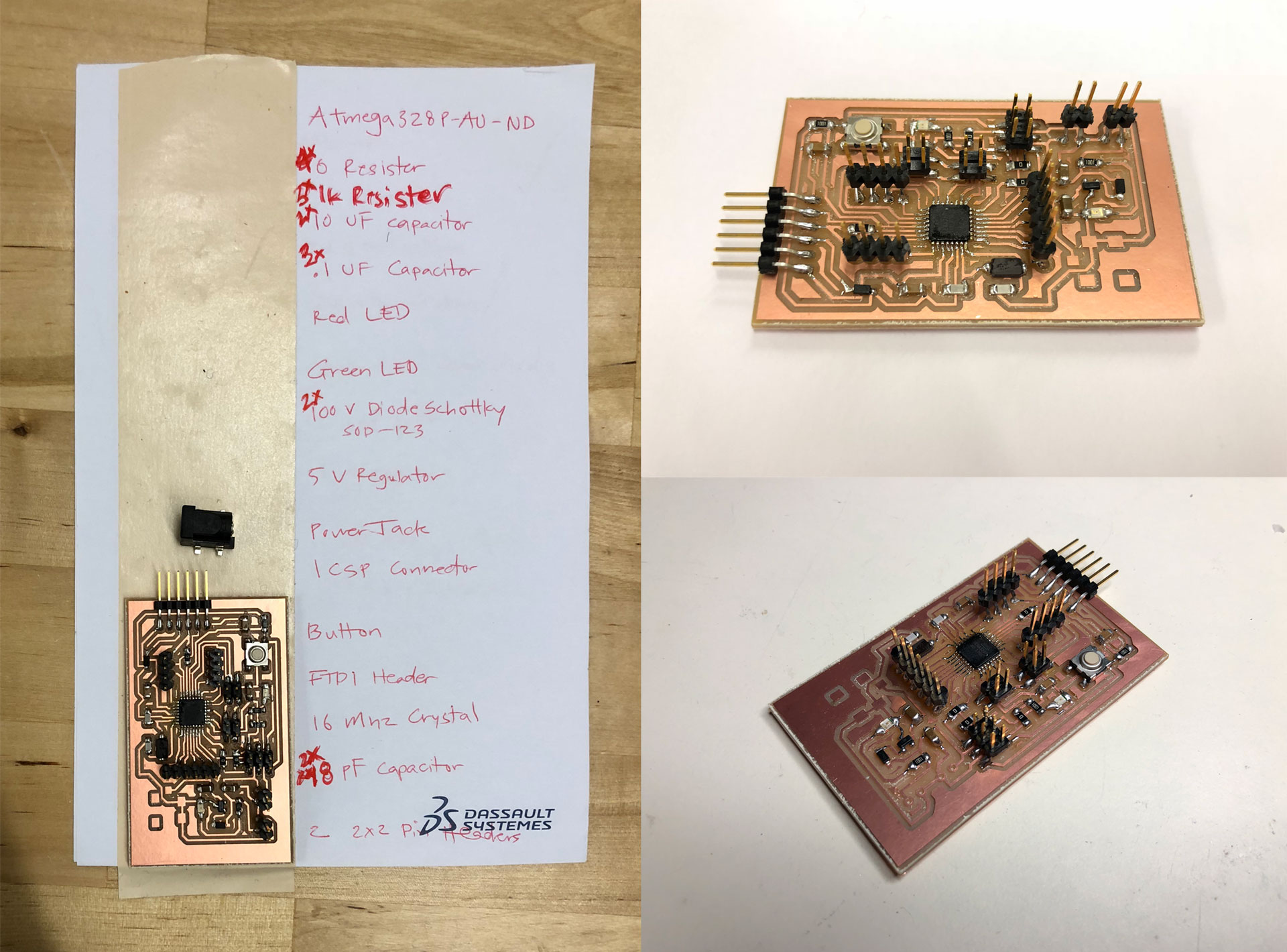
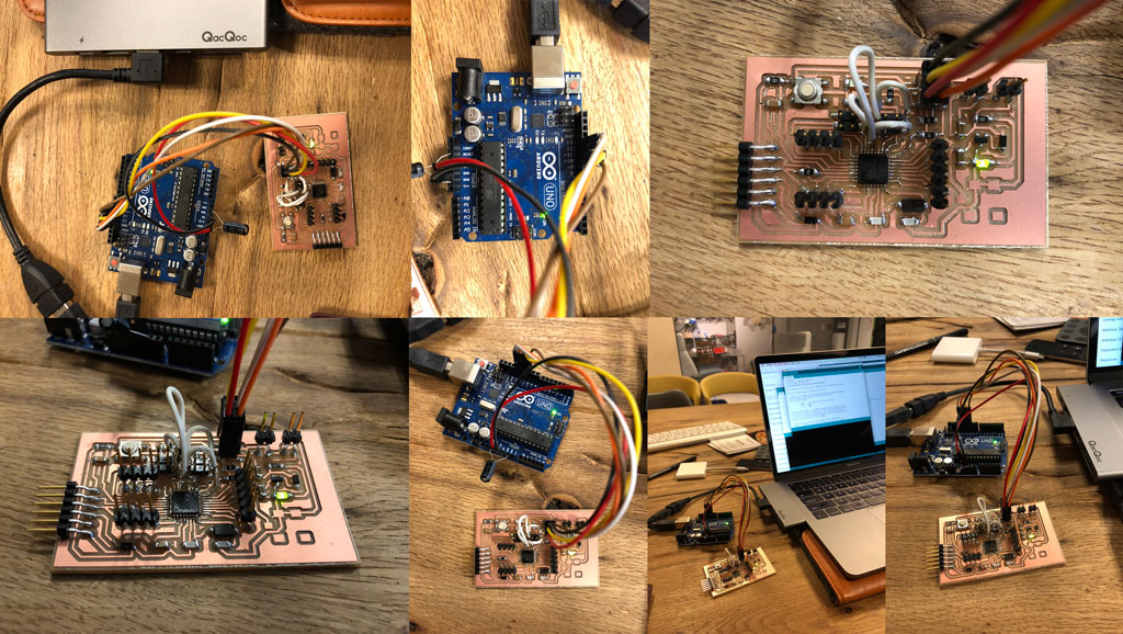
After designing my Sabaduino board in Eagle, I milled it using the Roland SRM 20 at our lab. It took a couple of tries to mill the board and make sure all the traces cut through. I stuffed the board with all the components and nearly forgot that I had to add some jumper wires to connect 2 traces. Being a single-sided board and given the complexity of the trace layout and desire to maintain a very small footprint, I could not get the traces to be designed without overlapping, so instead I opted to solder a couple of jumper wires to connect two connections. A couple of weeks later, I worked on a new board design that eliminated the need for these jumper cables. This second board (Sabaduino 2.0) is larger than my Sabaduino 1.0 board, but I realized that in my final project, I have extra space for a larger board anyway.


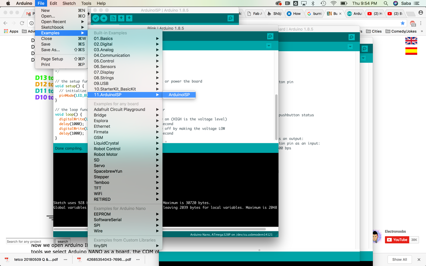
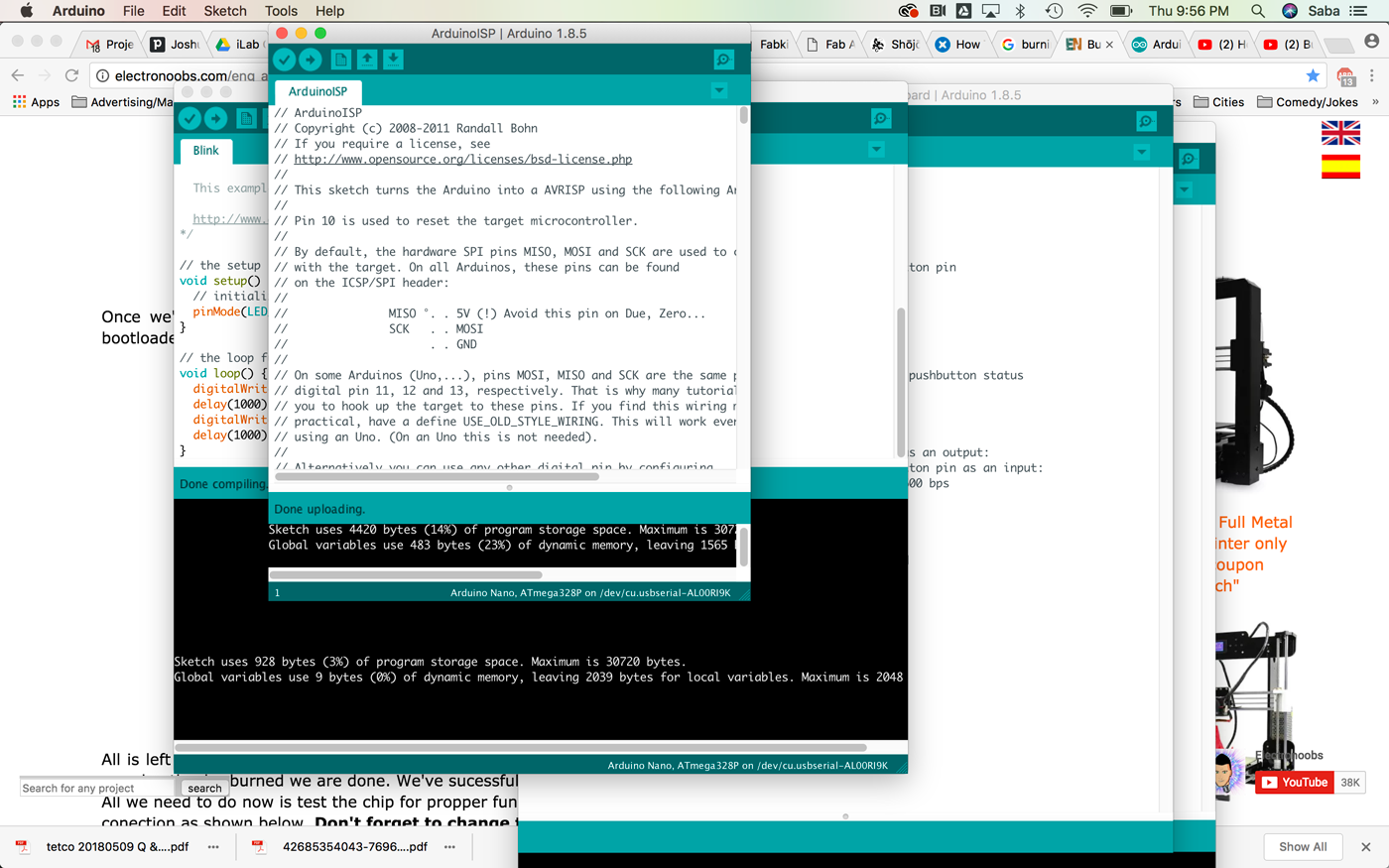
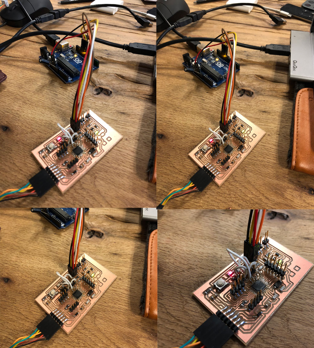
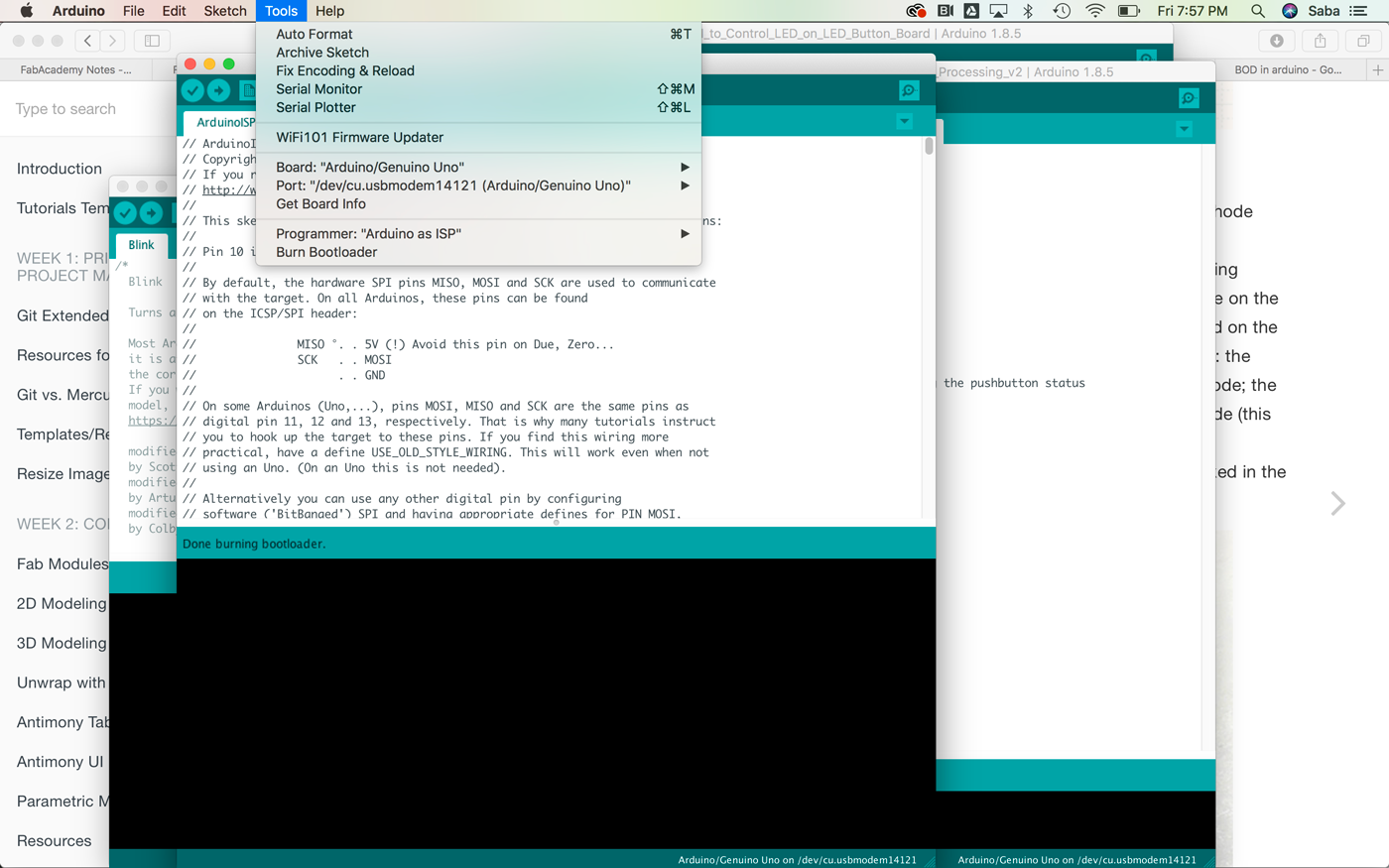
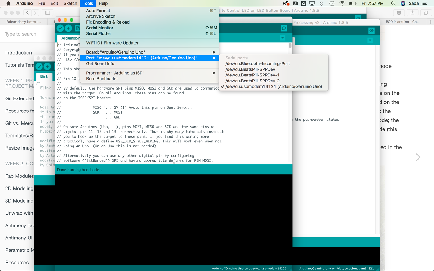
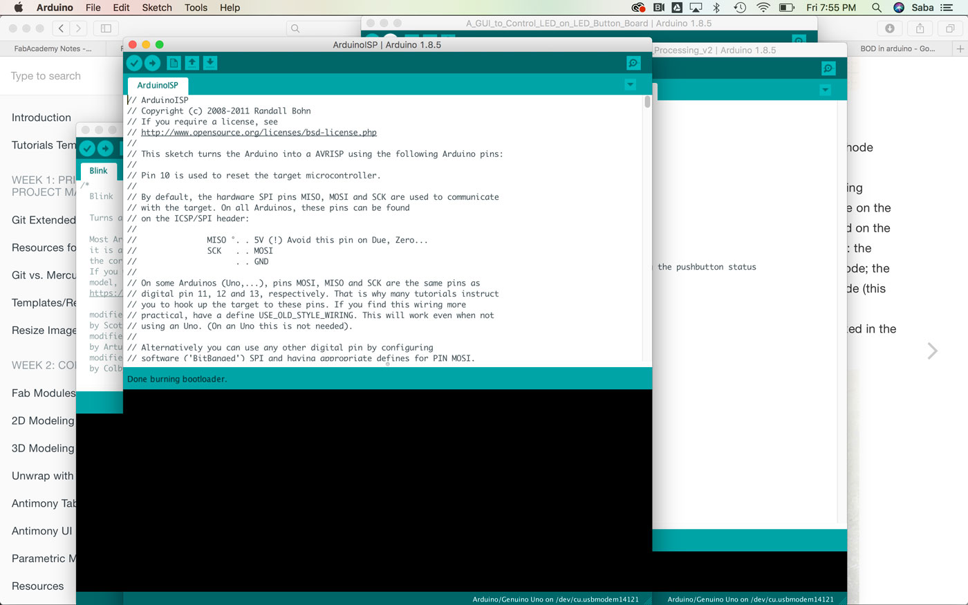
To set up my Sabaduino board, I had to burn the bootloader. I used the Arduino IDE to do this and an existing Arduino microcontroller board as the programmer since the specs are about the same. This took me a few tries, as I didn’t quite know what the settings should be for the board type and which Arduino board to use. I read online that many people had used the Arduino Nano to burn the bootloader onto their new Arduino-esque boards. I tried that quite a few times with different settings with no success. I finally decided to use a basic Arduino Uno with the most basic settings (Board set to Arduino Uno, Port set to appropriate port com, and Programmer set to “Arduino as ISP”), and viola! That worked seamlessly.
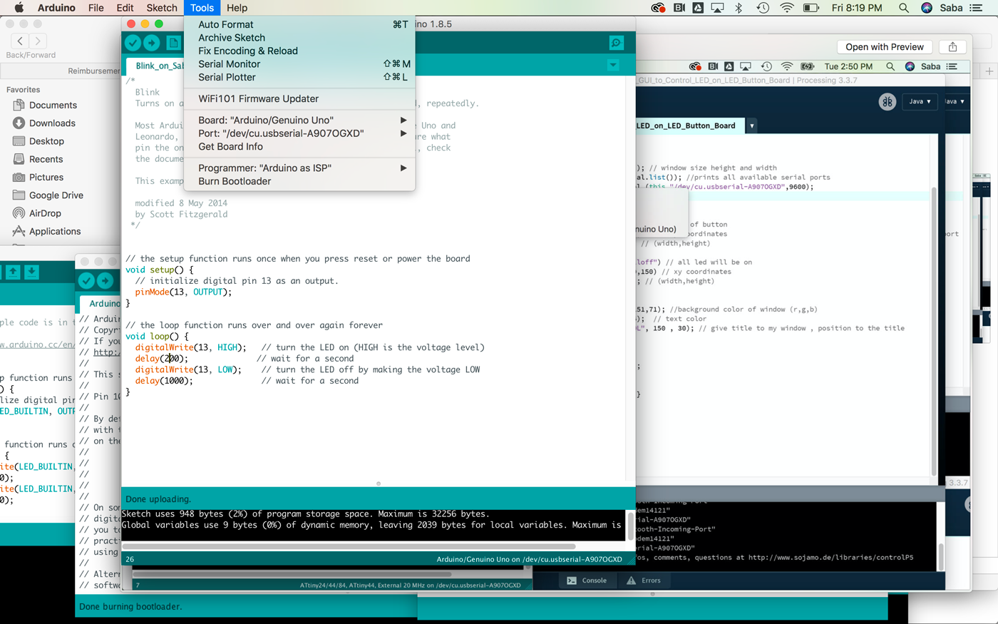
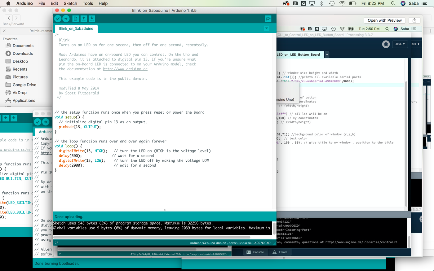
I then tested some basic blink code on my Sabaduino board, and it worked.

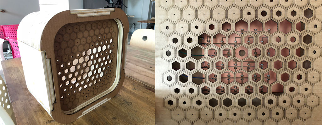
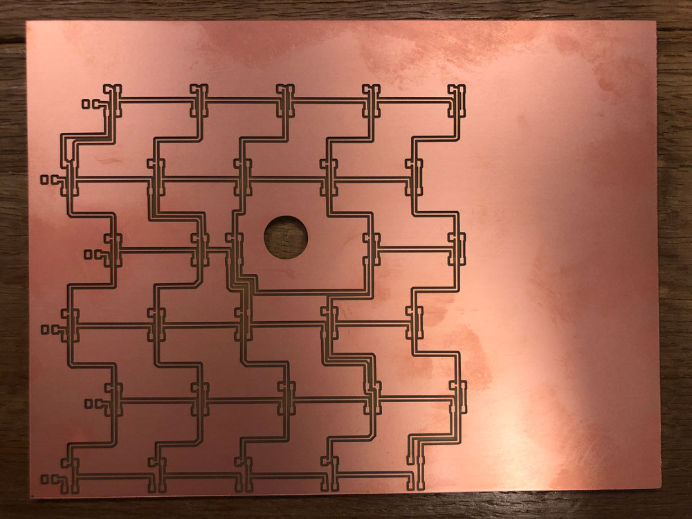
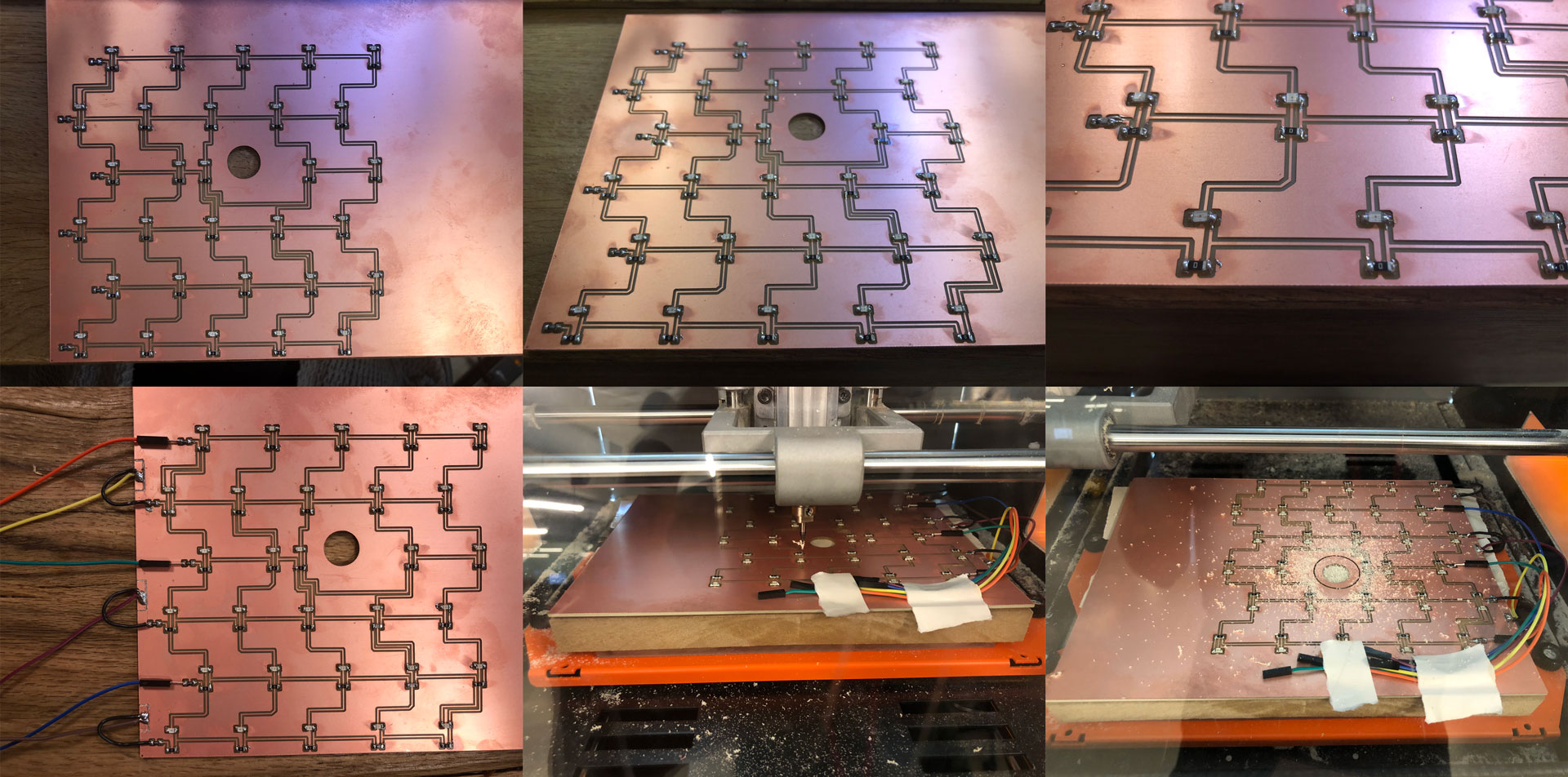
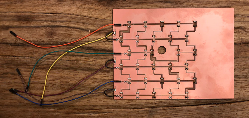
LED Charlieplex Board
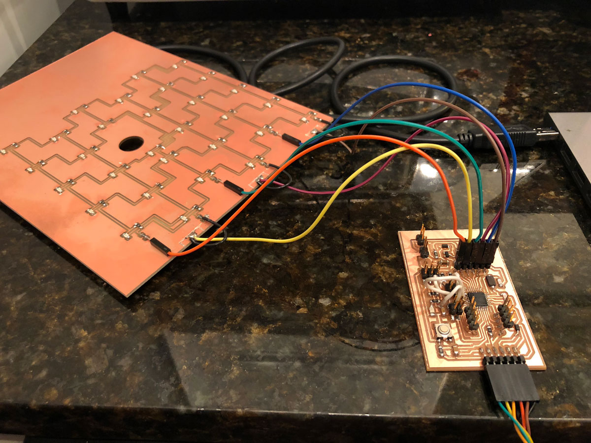
To create the matrix of LEDs for my Halftone Screen, I decided to use the charlieplexing method as a means to minimize the number of output pins connected to my Sabaduino Board. I worked on a 6x5 matrix of LEDs and mapped the traces in Eagle. I learned a lot about Charlieplexing online, and found the Instructables post to be quite helpful. It took some time to organize the board and place the LEDs in the exact position of the openings of my Halftone hex pattern. I imported a DXF into eagle of my Halftone screen which helped as a guide. I also added a hole where my PIR sensor would be located.
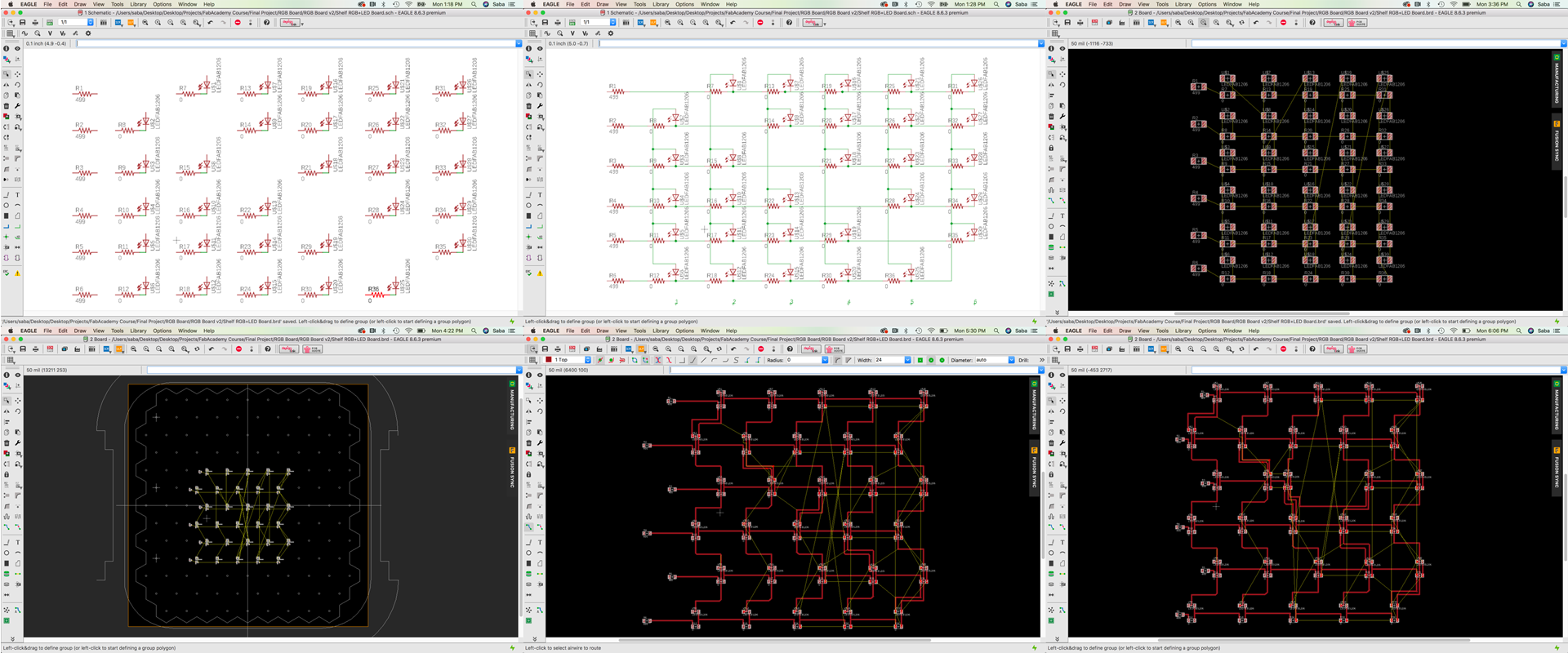
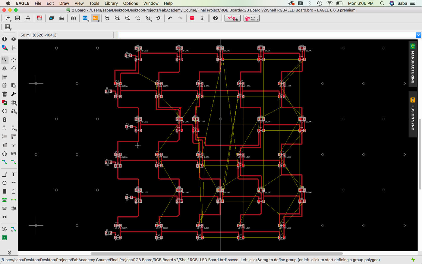
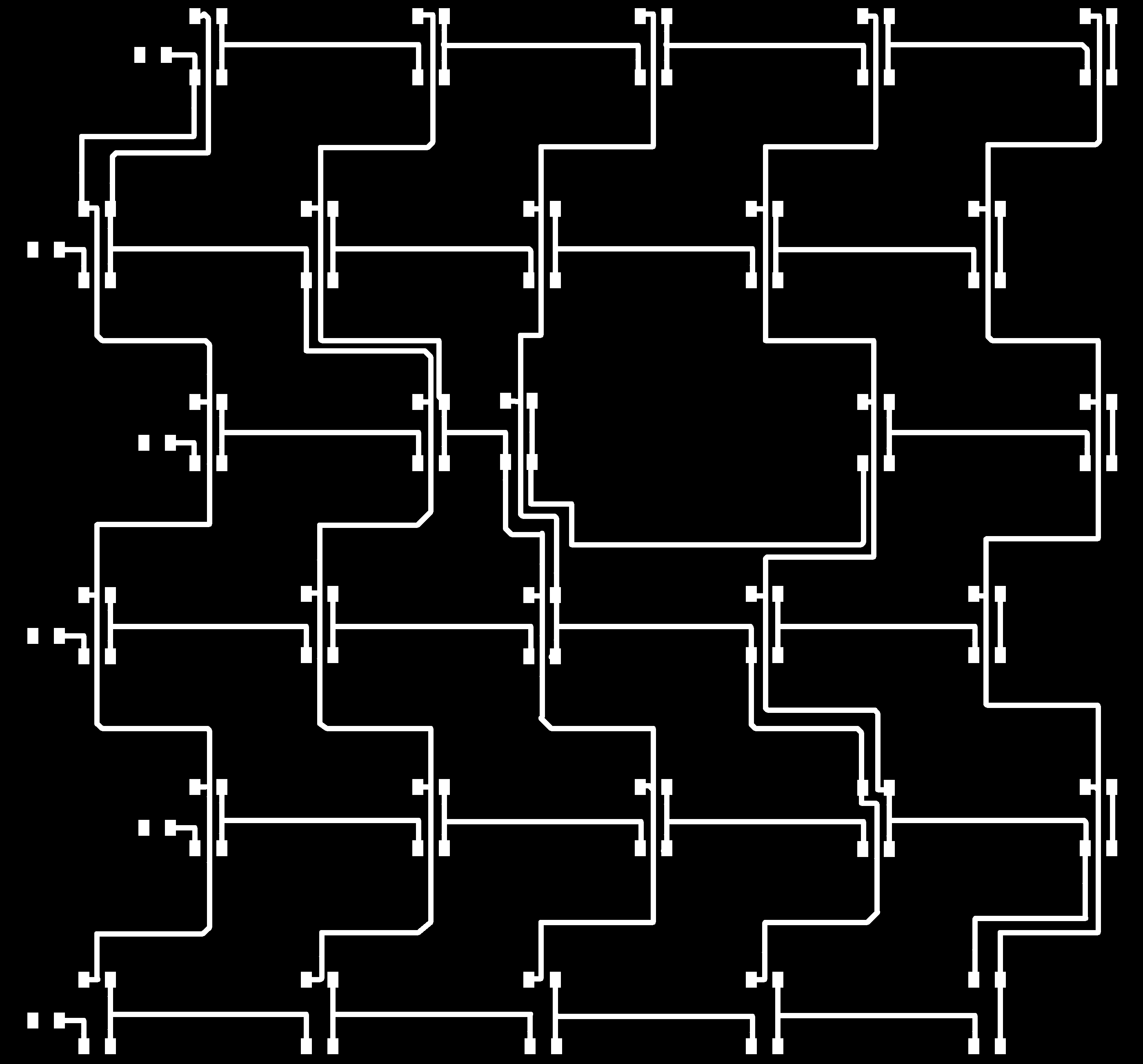

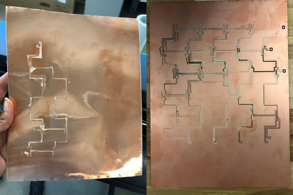
Realizing the large size of the board, I tried a couple of options as far as producing the board. I first attempted to vinyl cut the traces, but realized that given the thinness of the traces, it would be pretty difficult. I then tried tomill the board using the Roland SRM-20 in our FabLab, but didn’t get a consistent cut throughout the board and despite being taped down, the board was moving on the sacrificial material quite a bit. With Luciano’s help (one of our instructors), I finally was able to mill a successful board using the Roland machine at the CiC in Boston. I stuffed the board with the LEDs and resistors, and also added the connecting cables. I realized that the hole that I had drawn in Eagle for the PIR sensor was too small, so I braved re-cutting the hole with the components on the board in our Roland machine. I held my breath as the machine cut out the larger hole (barely missing a few components - whew!).
PIR Sensor Board
For the design of the PIR Sensor Board, please refer to Exercise 10 - Input Devices.
Embedded Programming
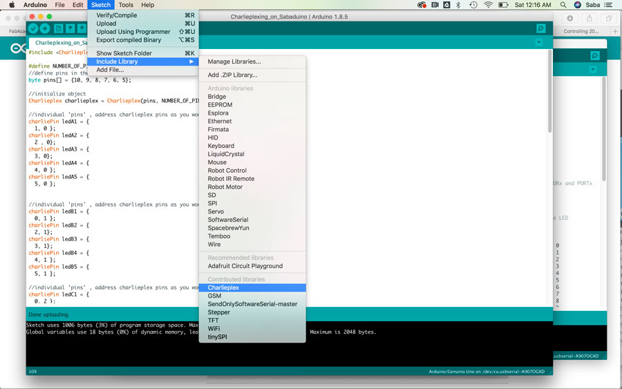
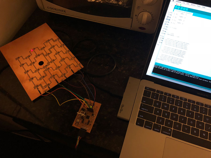
The first part of my programming sequence was to test my Charlieplex Board. I downloaded the Arduino Charlieplex library and installed it in the library folder of Arduino.
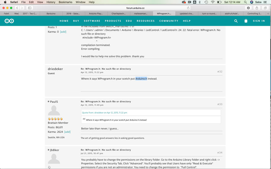
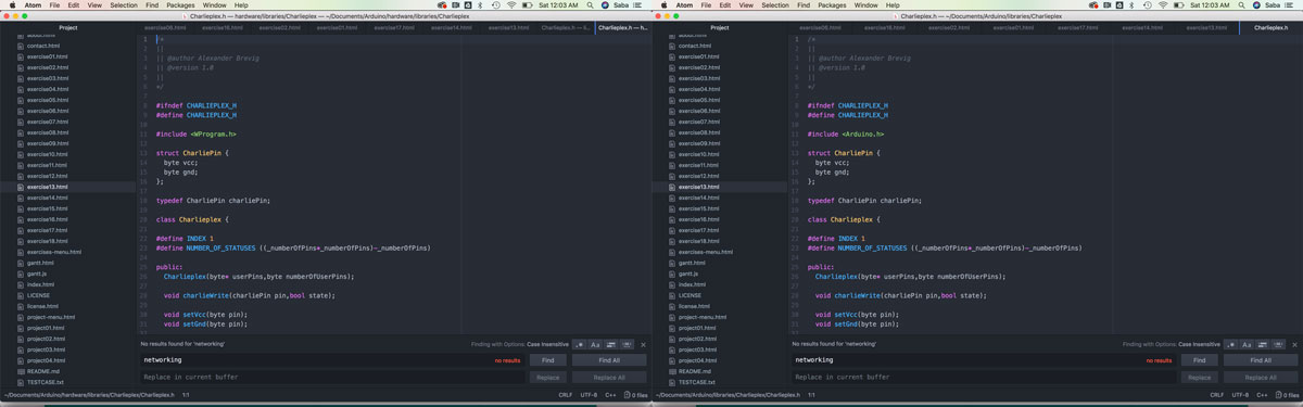
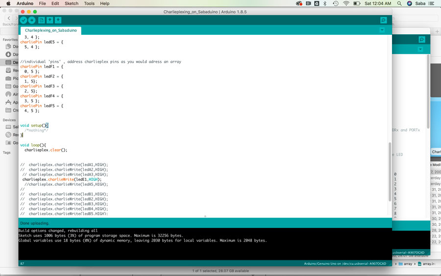
I connected my Charlieplex Board to my Sabaduino Board, and then tried to upload the code onto my board, but kept getting an error message around the Charlieplex library that stated “WProgram.h: No such file or directory.” I did some research online and saw some posts around the WProgram.h library within the Charlieplex library needing to be updated to a different library when using the newer Arduino Unos. I updated this library in the Charlieplex library code from “WProgram.h” to Arduino.h” and tried uploading my code again. It worked! I was able to upload the code and a pixel on my Charlieplex board lit up.
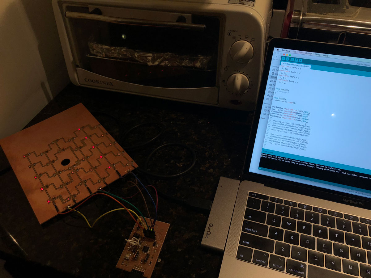
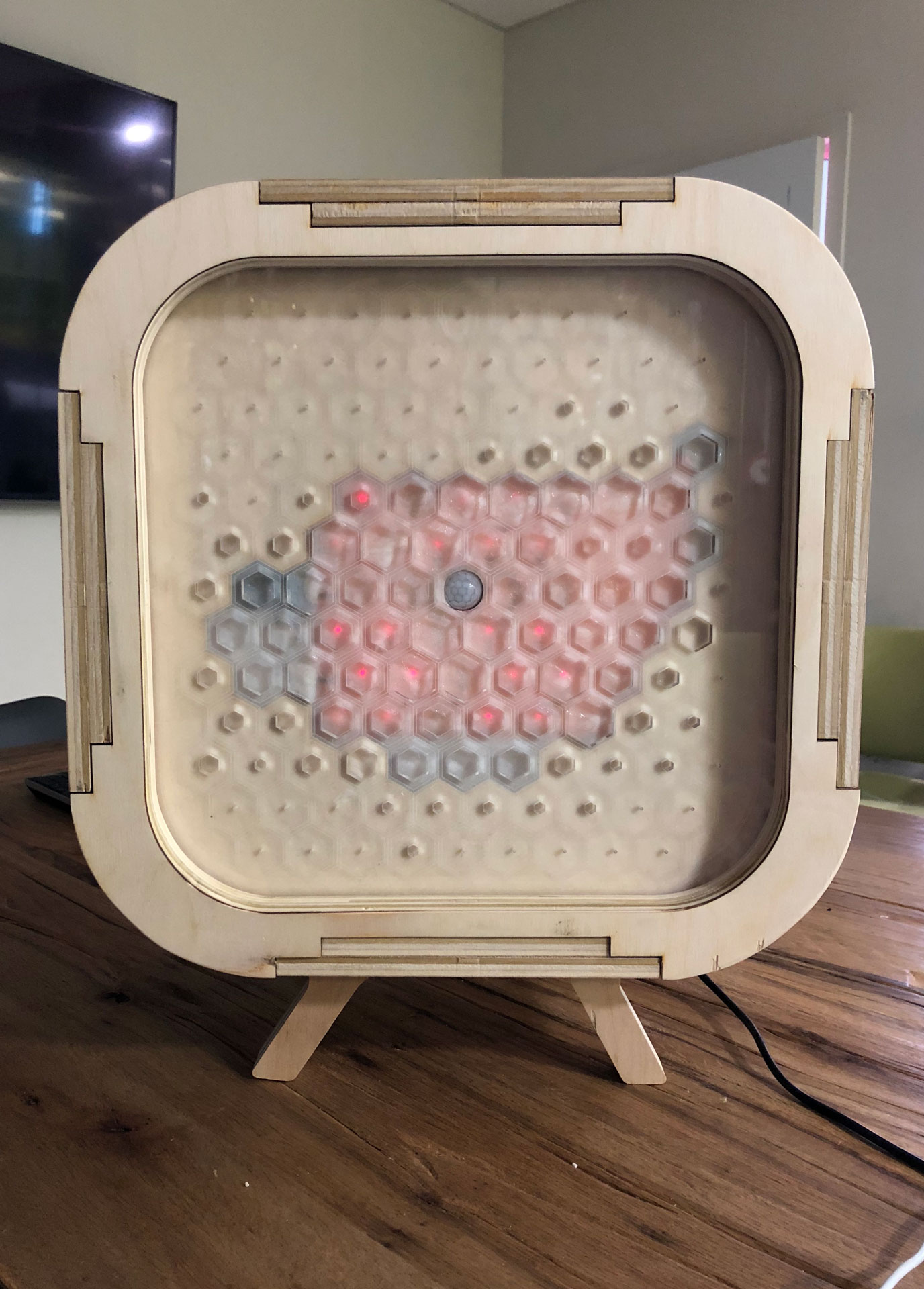
Now that I had tested each of the boards individually, it was time to integrate and connect all of my boards and program my Sabaduino board to take input from the PIR sensor and output lighting sequences. As I mentioned earlier, Pixie has 3 states: Dormant, Aware, and Interactive. In the Aware state, Pixie senses motion and wakes up, or its lights turn on.
I connected both the PIR Sensor Board and Charlieplex Board to the Sabaduino Board and began testing some code. I first tested the Charlieplex code from before to make sure my board was working after it had been assembled as part of the screen, and to make sure no components were broken. Everything worked fine. Now it was time to test my updated code.
It was the moment of truth, to see if Pixie would work in its Aware state. I wrote a program that would take sensor data from my PIR sensor and when there was motion, the lights on my Charlieplex Board would activate and turn on in sequence. Pixie was aware!!!
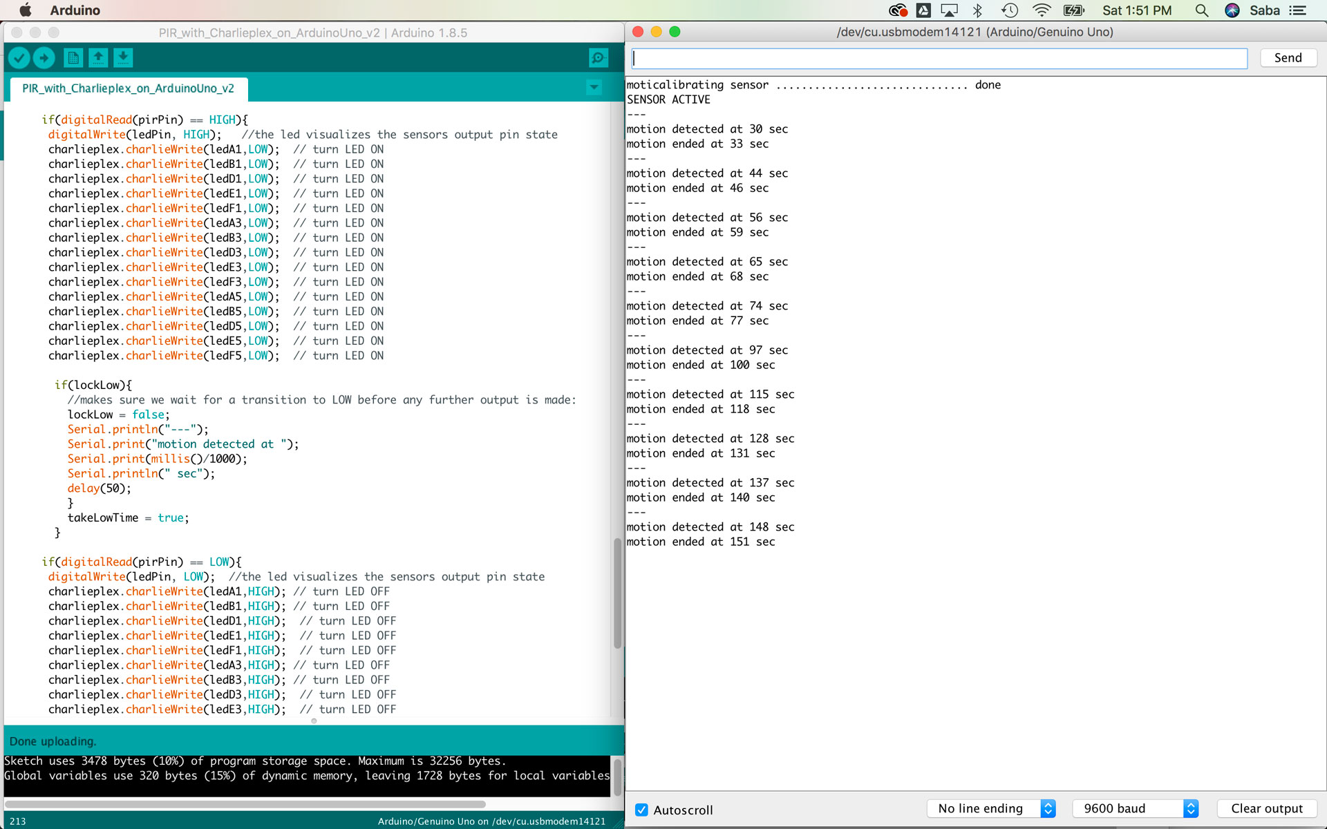
I tried to get the serial monitor to work and display a message “motion detected” when motion was senses by the PIR sensor, but could not get the serial monitor to work. I will have to return back to this in the future.
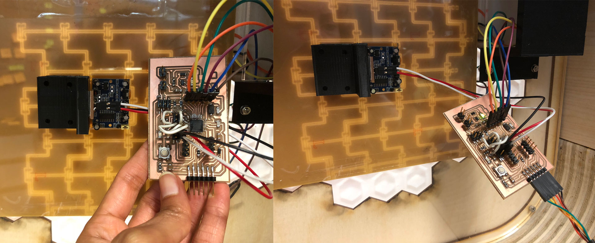
Calibrating PIR Sensor
I created an updated program that begins by calibrating my PIR Sensor. I found sample code on the Arduino site and tested it with serial monitor code.
I then integrated this code with my Charlieplex and PIR sensor code, and it worked great.
I tried one last program, and created a sequence where the LEDs on the Charlieplex board light up. The idea that I hope to achieve is to have the Charlieplex Board produce a simple message “Hi” when motion is detected in its Active state. After programming the Charlieplex Board and experimenting, I am realizing that the board is really great for addressing specific LED pixels, but much tougher to program a group of LEDs to light up in a particular way. This will take some advanced programming that I plan to research and learn more about.
Blowing Up Sabaduino
Well, there is only one grand way to end Fab Academy...by blowing up my dearest board.
So, I got a bit more adventurous and decided to add a button component to my board that would ultimately be used to control the Charlieplex Board. I began by testing out a program that would turn the onboard LED on the Sabaduino Board on and off, and also send a message to the serial monitor when the button was pressed. I got this to work and the serial monitor to read when the button was pressed by writing “Hello World.” I then connected the button to the Charlieplex Board and was able to get the button press to turn the Charlieplex Board of LEDs on and off when the button was no longer pressed. This worked beautifully and I was beyond elated when I started to smell something odd….I mild burnt smell. I smelt my Sabaduino board and it seemed to be smelling strange, and I saw my serial monitor in a frenzied state. I immediately unplugged the board from my computer, and my fear set in. I had likely fried my board. I tried to test the basic blink code, but it wasn’t uploading. After 5 minutes, it finally uploaded, but the LED was not lighting up and my serial monitor was still sending the “Hello World” message from the last program. Clearly, my board had shorted.
I was worried that my Charlieplex Board had shorted too. I decided to use an Arduino Uno with my PIR Sensor Board and Charlieplex Board and test the components. Both boards seemed to be working fine, a small sigh of relief. After Fab Academy, I plan to spend some time fixing the short in my Sabaduino Board, and if it’s unfixable, then I will build my Sabaduino 2.0 Board.
E:: Final Assembly, Questions, Implications, and Future Iterations
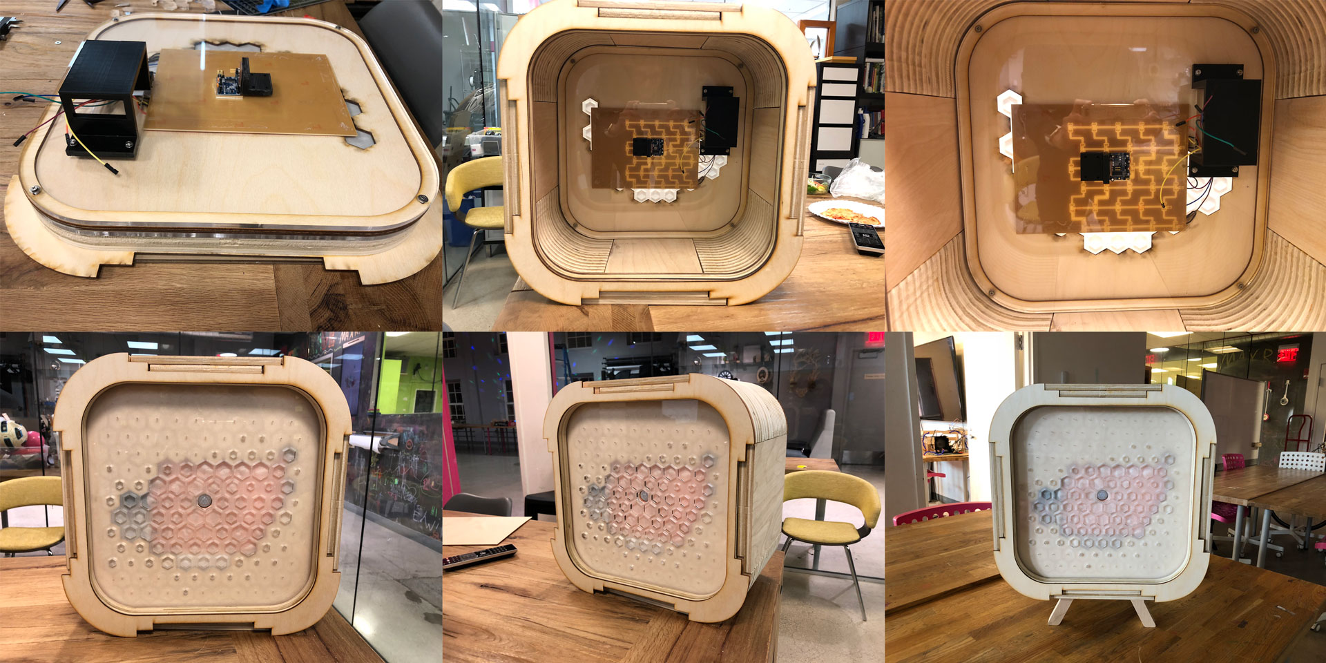
Overall, I am really pleased by Pixie and what I was able to accomplish. The assembly and electronic components came together quite beautifully, and the final piece is a work in progress with many more screens that I hope to design and use as a tool for teaching many skills to students, both young and old. So far, people’s reaction to Pixie has been one of delight and intrigue, which is what I hoped for. Blowing up Sabaduino 1.0 just means that I am ready to design Sabaduino 2.0. I was pleased with how the Charlieplex Board was integrated into the design of the Halftone Screen. Creating a well designed interactive object takes a lot of focus and skill, and going back and forth between the electronics and physical design of the object was critical to my development process.
In the future, I hope to add more components, such as a physical controller to control the Charlieplex Board that will be used in Pixie’s Interactive state and also add sounds. I would also like to update the LEDs on the Charlieplex Board to brighter Galium Nitride LEDs
Pixie should encourage users to interact with it and with one another. To me, that is how I will be able to evaluate its future success. I had a lot of questions around the responsiveness of people to Pixie, and my initial questions around it’s appeal and basic interactive quality have been answered: a genuine sense of curiosity is arisen by people who see Pixie. I do wonder how people with disabilities can interact with Pixie, and I hope to add more senses to Pixie over time, such as touch and sound.
I do feel that there is much to develop through Pixie’s Screens. It’s a canvas upon which I and other can develop many tools, some educational, some for play, and others for amusement. I am also happy that almost all the parts (except for the screws) used to design Pixie can be found at a FabLab and designed at a FabLab. It truly makes Pixie an open source platform for people to further build upon.
F:: BOM (Bill of Materials)
For the design and fabrication of all of Pixie’s components, below are the bill of materials (BOM). All the components used in the design and fabrication of Pixie are available at a FabLab or can be built at a FabLab, except for the 8 wood screws that I bought from Home Depot.
Armature & Screen
Sabaduino ATmega328 Board
Charlieplex Board
PIR Sensor Board
G:: Licensing
I plan to use the Creative Commons license, as follows:
(c) Saba Ghole, June 2018.
This work may be reproduced, modified, distributed and displayed for any purpose but must acknowledge my project. This work is provided as is; no warranty is provided, and users accept all liability.
H:: Design Files
Download Rhino, Fusion 360, Arduino, Eagle and milling files for creating Pixie.
Click to download Rhino .3dm file for Pixie's Halftone Screen.
Click to view Fusion 360 .f3d file for Pixie's Halftone Screen and 3D printed board holders.
Click to download Eagle .sch file for Sabaduino Board.
Click to download Eagle .brd file for Sabaduino Board.
Click to download PNG file for Sabaduino Board Traces.
Click to download PNG file for Sabaduino Board Outline.
Click to download PNG file for Sabaduino Board Holes.
Click to download Eagle .sch file for Charlieplex Board.
Click to download Eagle .brd file for Charlieplex Board.
Click to download PNG file for Charlieplex Board Traces.
Click to download PNG file for Charlieplex Board Outline.
Click to download Arduino .ino file for Blink Program on Sabaduino Board.
Click to download Arduino .ino file for Charlieplex Program on Sabaduino Board.
Click to download Arduino .ino file for Charlieplex and PIR Sensor Program on Sabaduino Board.
I:: Acknowledgements & References
Barduino
ATmega328 Data Sheet
Arduino as ISP and Arduino Bootloader
Burning Bootloader with Uno
PIR Sensor Datasheet
Arduino PIRsense code
Arduino Charlieplex Library and Sample Code
Charlieplexing in Arduino
Charlieplexing + Processing (Katerina Labrou)