Group Project: Test runout, alignment, speeds, feeds, and toolpaths for your machine
Individual Project: Make something big
My Process (Machining my Interactive Shelf)
:: March 12, 2018 ::
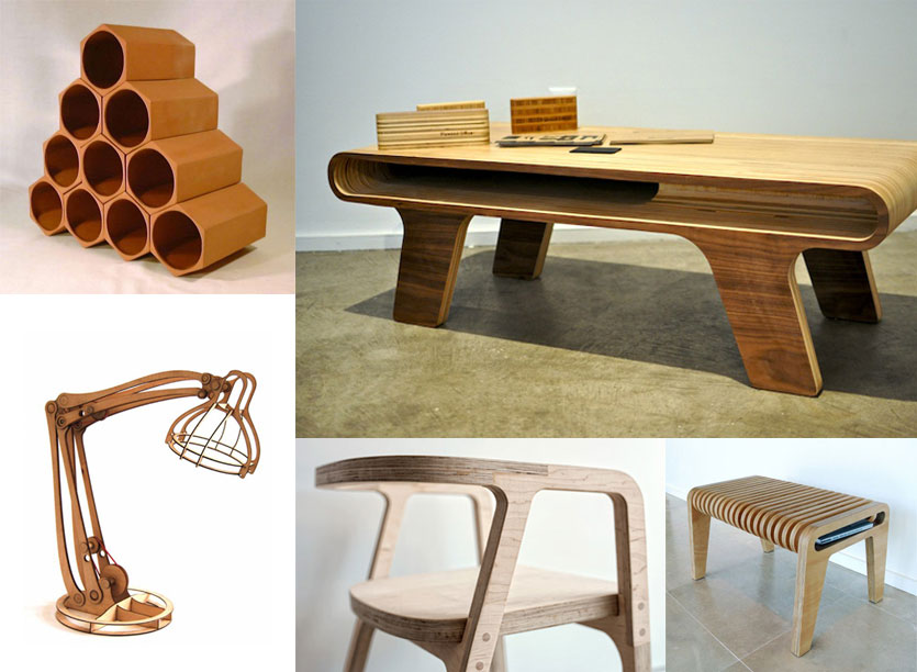
Precedents & Initial Designs
Our assignment this week was two part: 1) A group assignment to test runout, alignment, speeds, feeds, and toolpaths for our machine, and 2) an individual assignment to make something big using a CNC machine.
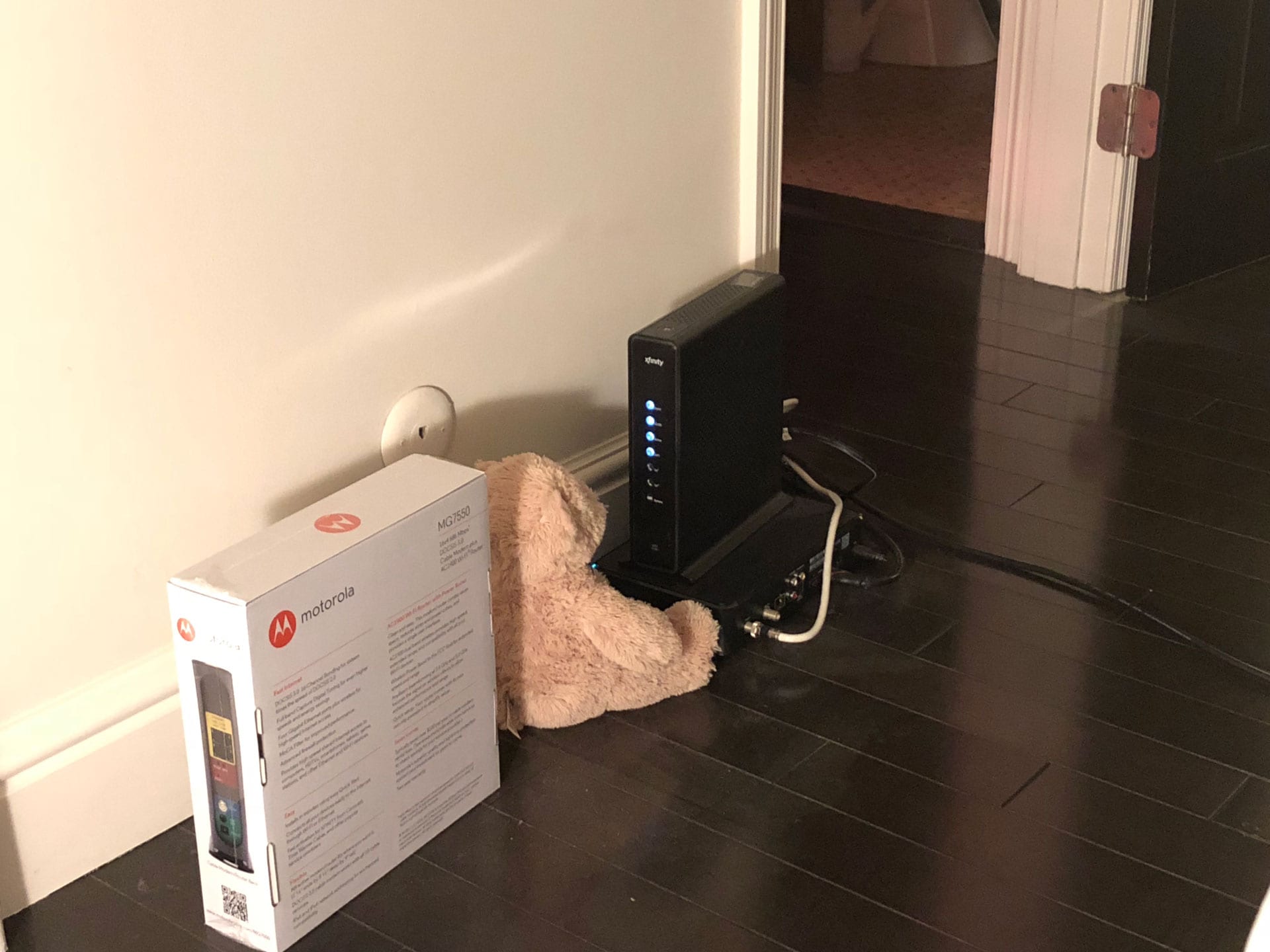
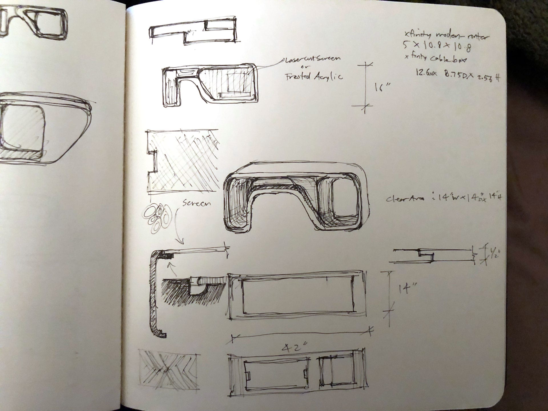
I was excited about this week’s assignment, as I have been wanting to build something large scale for quite some time. I decided that my project should be something useful that I can use at home. One of the things I have been looking for is a housing/casing/shelf for my router-modem and cable box. Currently the two boxes sit on the floor in a very untidy manner and the light from the modem can be distracting at night when I am sleeping. I decided to design a compact casing-shelf for the two units based on a postmodern aesthetic which could also transform into an interactive shelf via a transformable face panel for kids and adults.
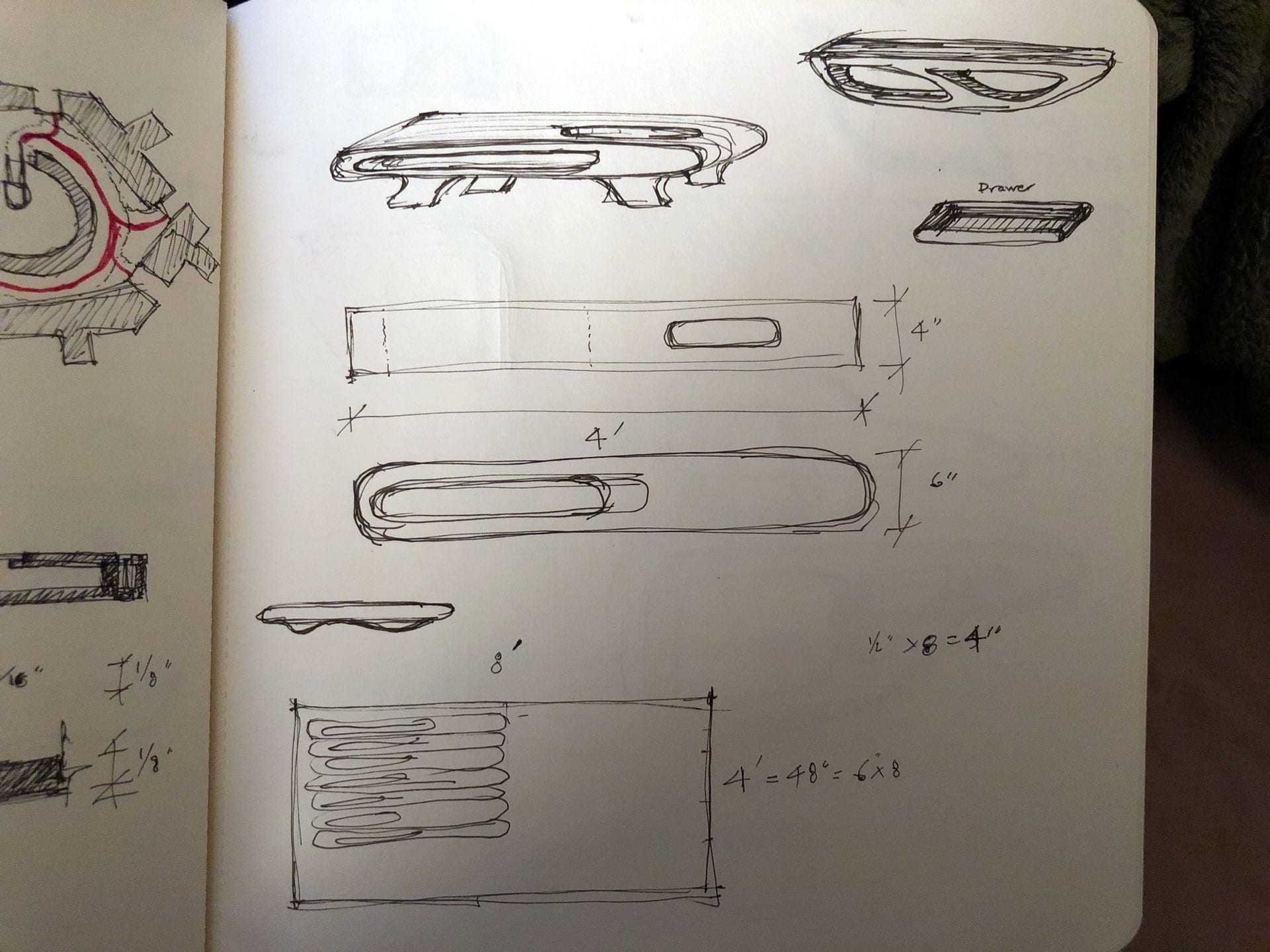
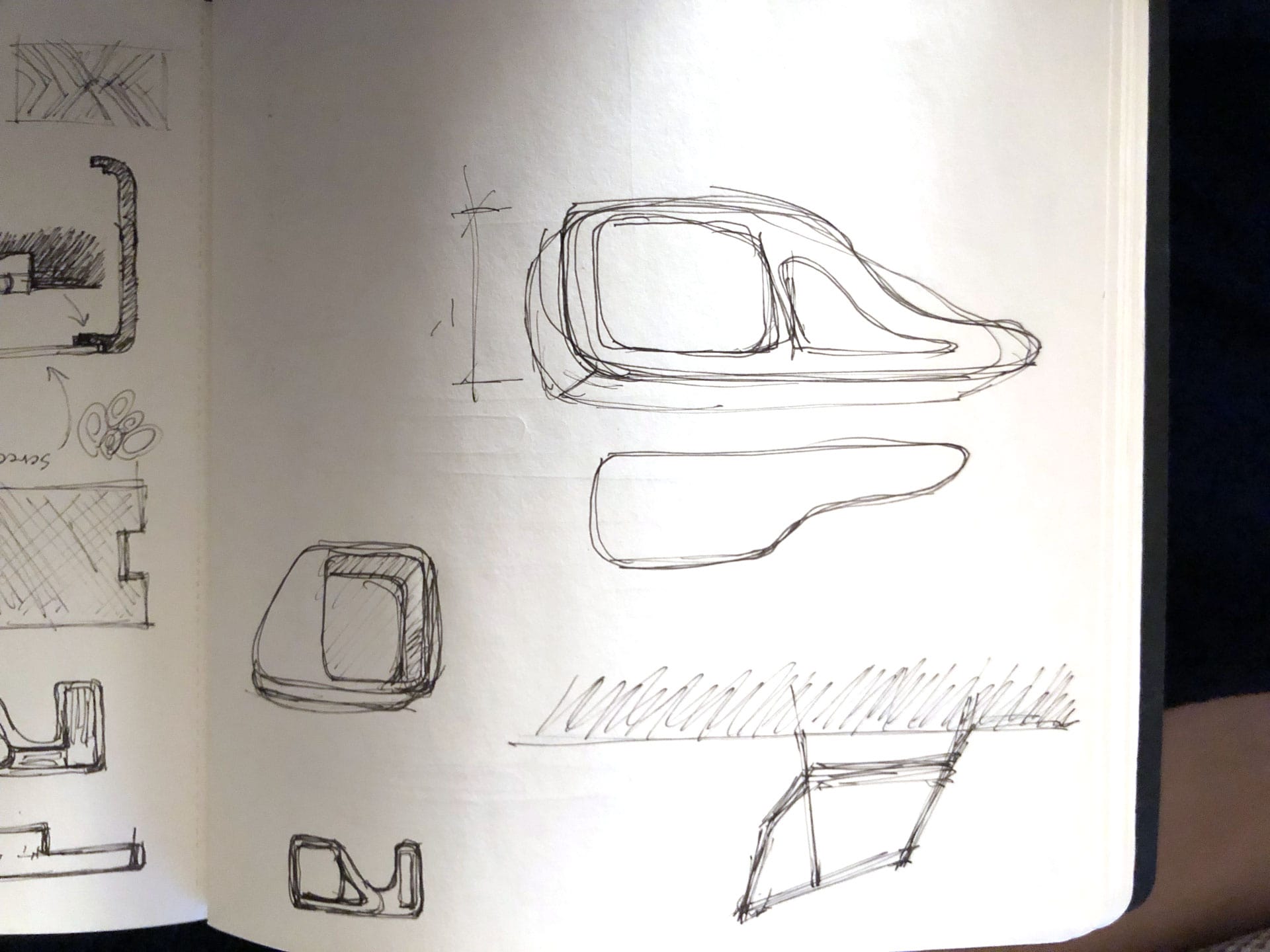
3D Design
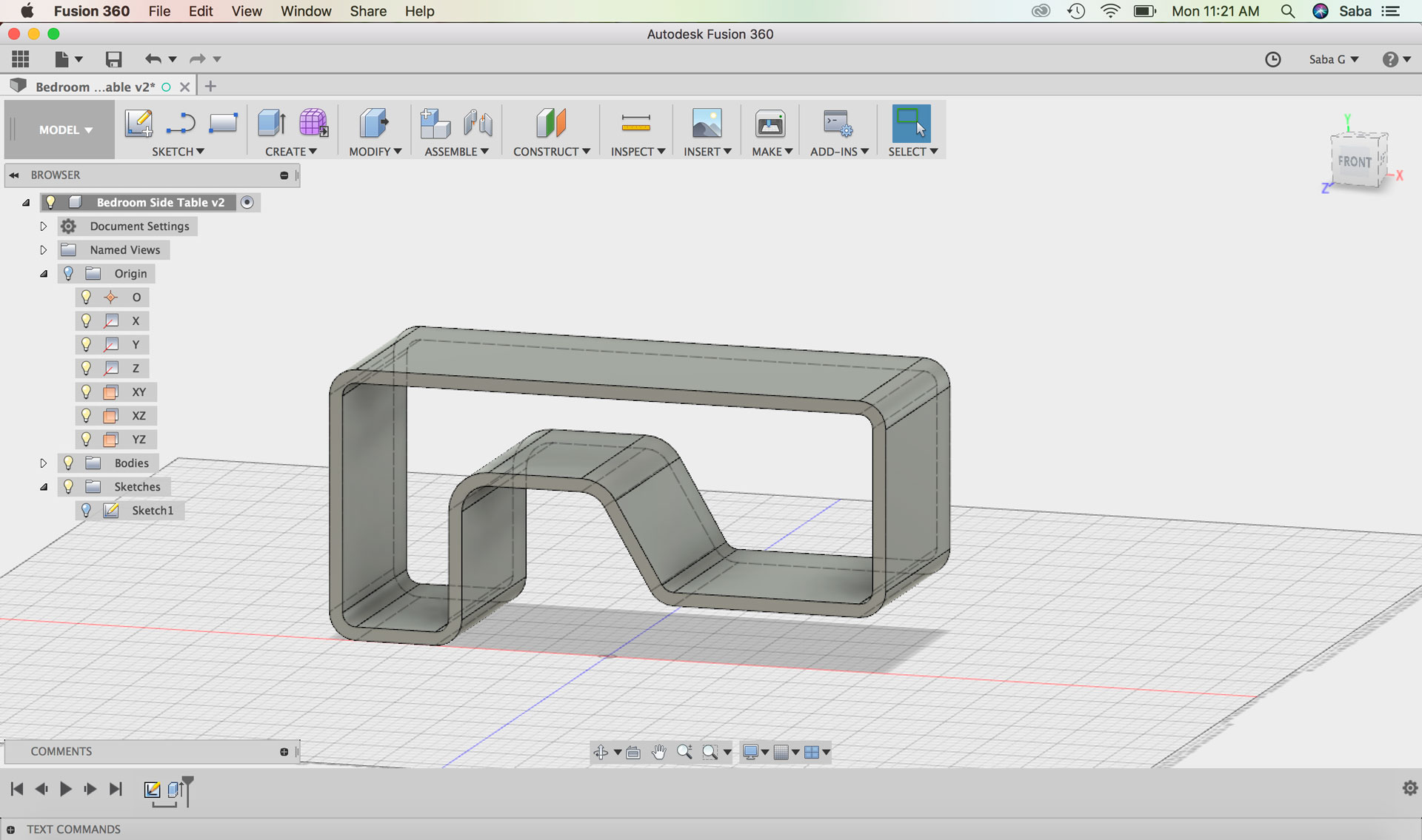
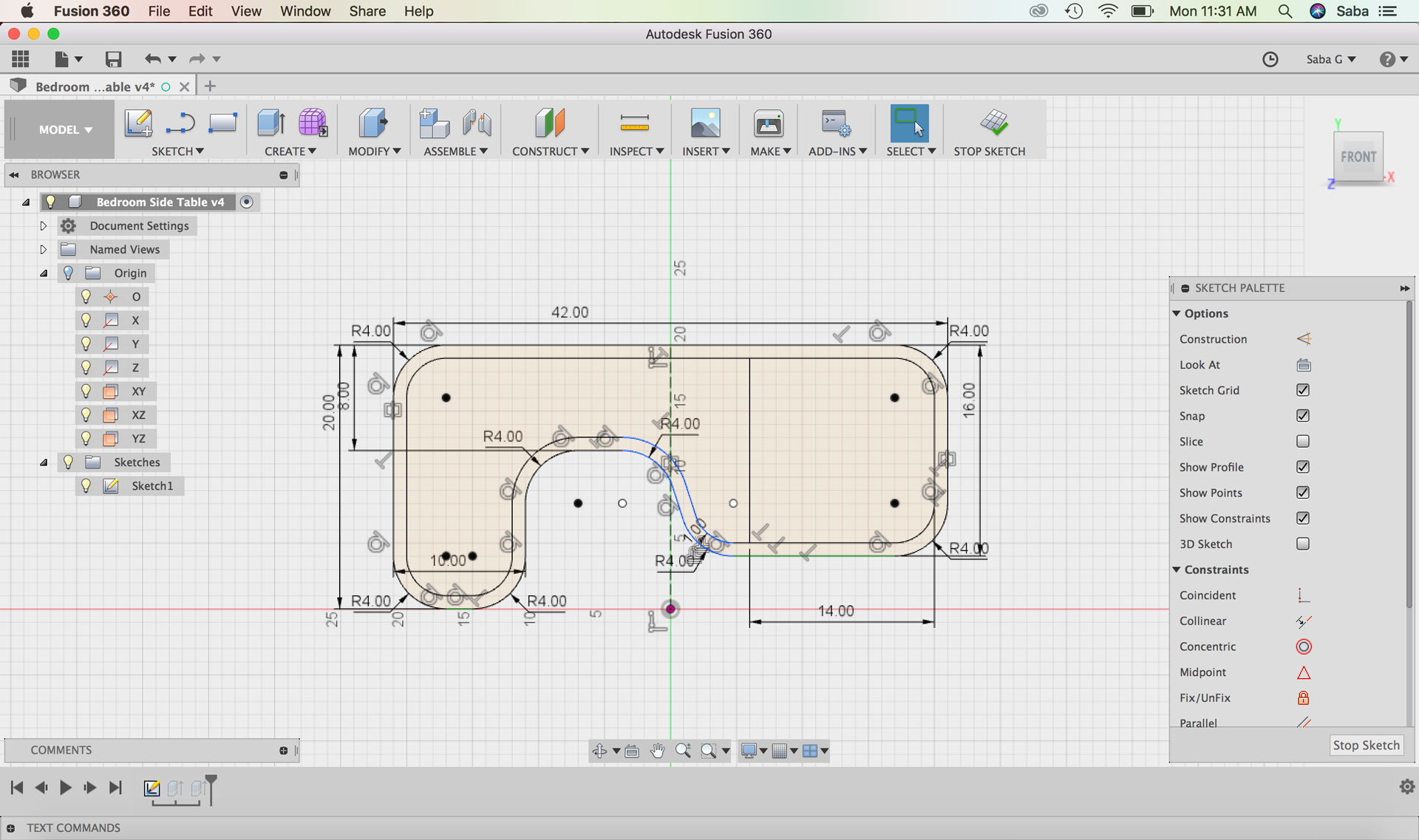
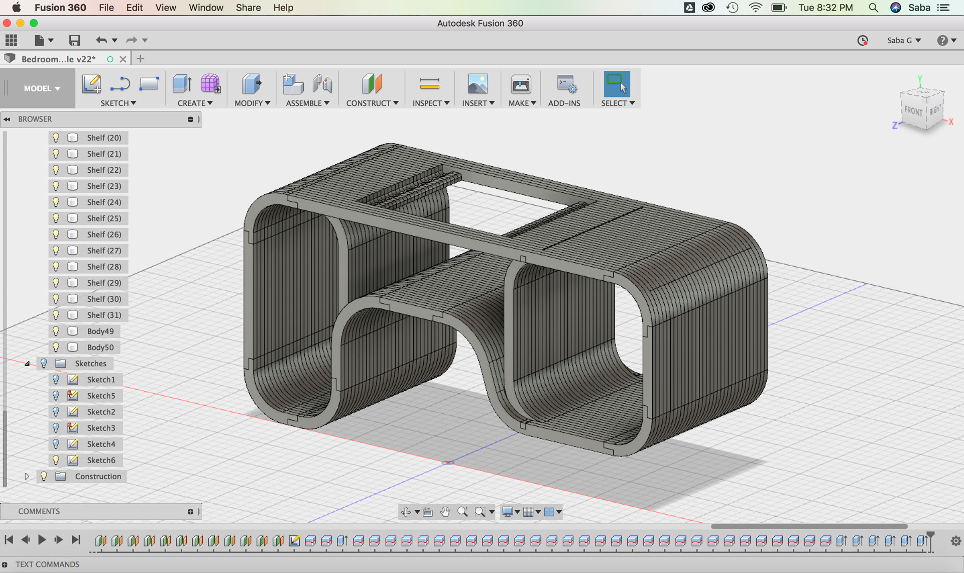
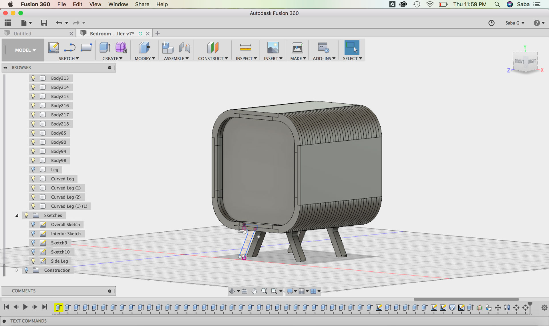
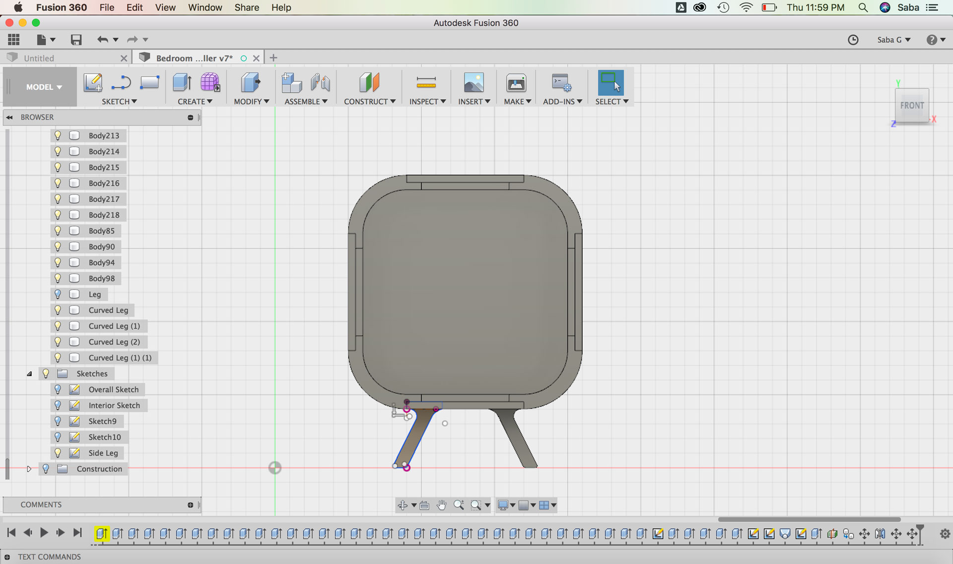
I worked through a number of different designs in Fusion 360 before arriving at my last and final iteration. My first design was a much larger shelving unit that included a dedicated space for the two units, but also another complementary space for books and items. I really liked the design, but when I started measuring this unit in my actual bedroom, it seemed to occupy too much space. I decided instead to edit the overall design and cut off the additional bookshelf, leaving only the space for the two units.
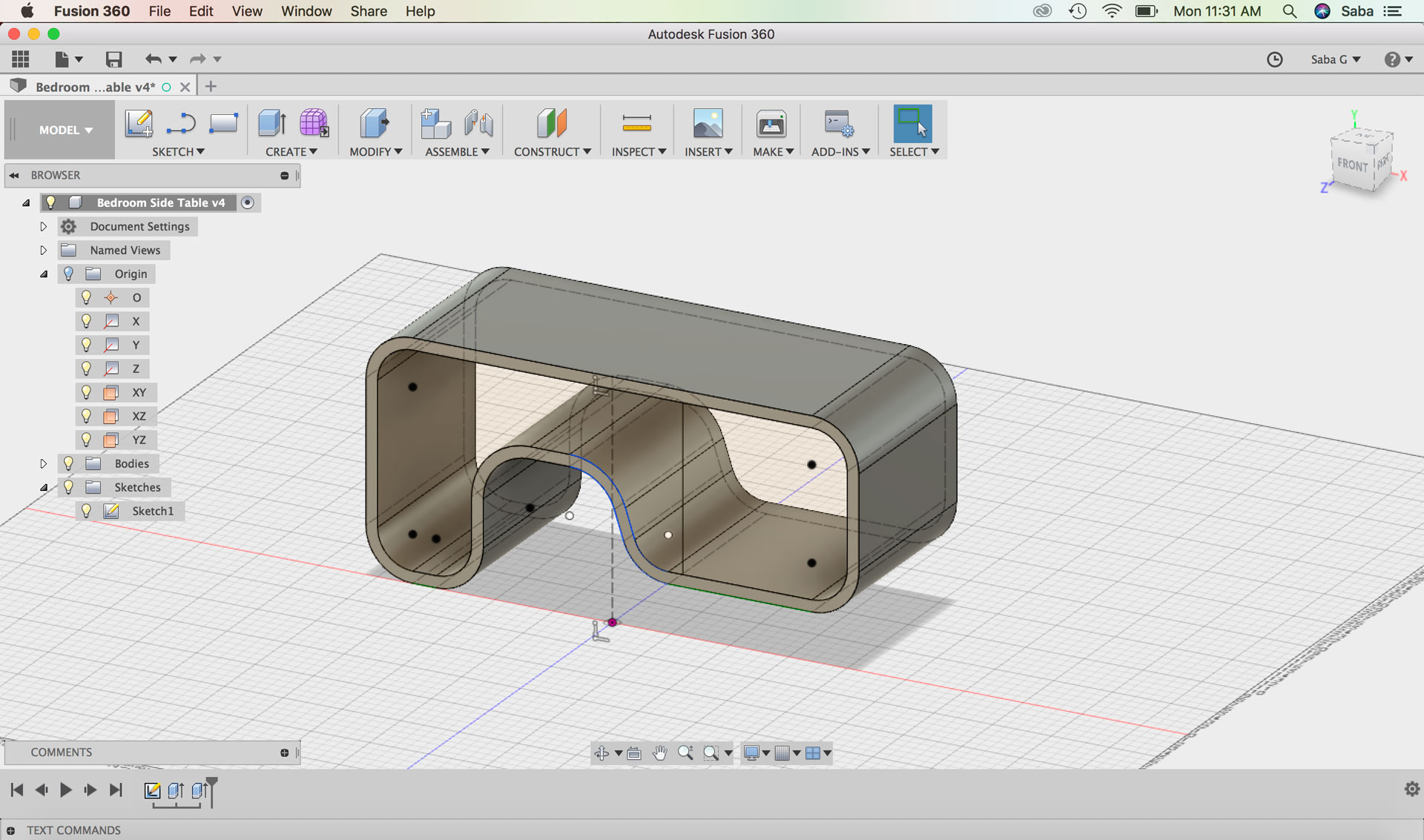
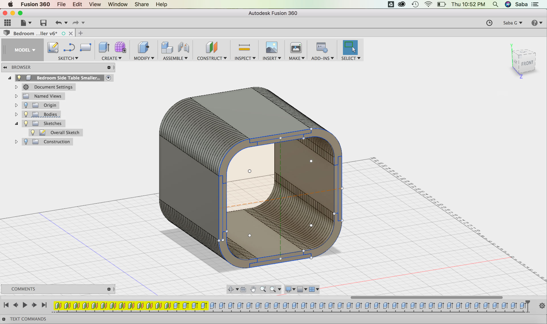
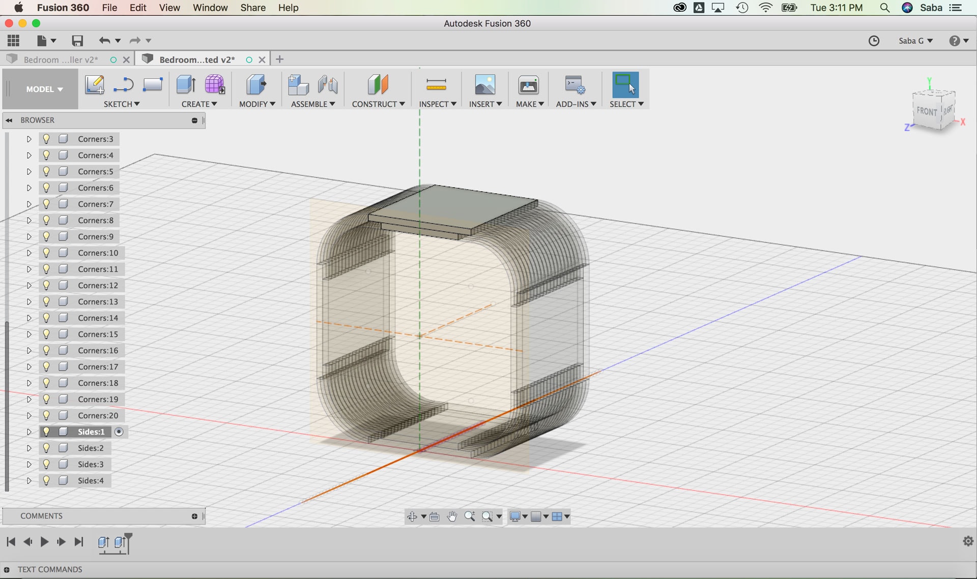
The second iteration felt much better, but still felt bulky. I reduced the overall depth of the piece from 16” to 10”, just enough to accomodate the two units stacked and open from the back to allow wires to go through to the wall outlet.
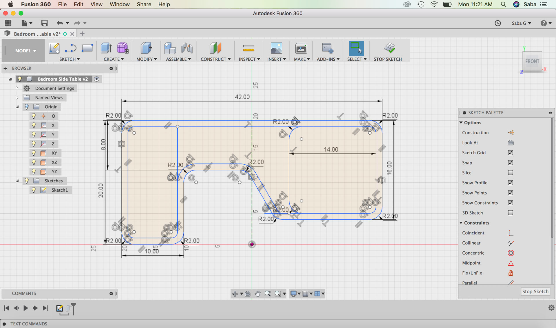
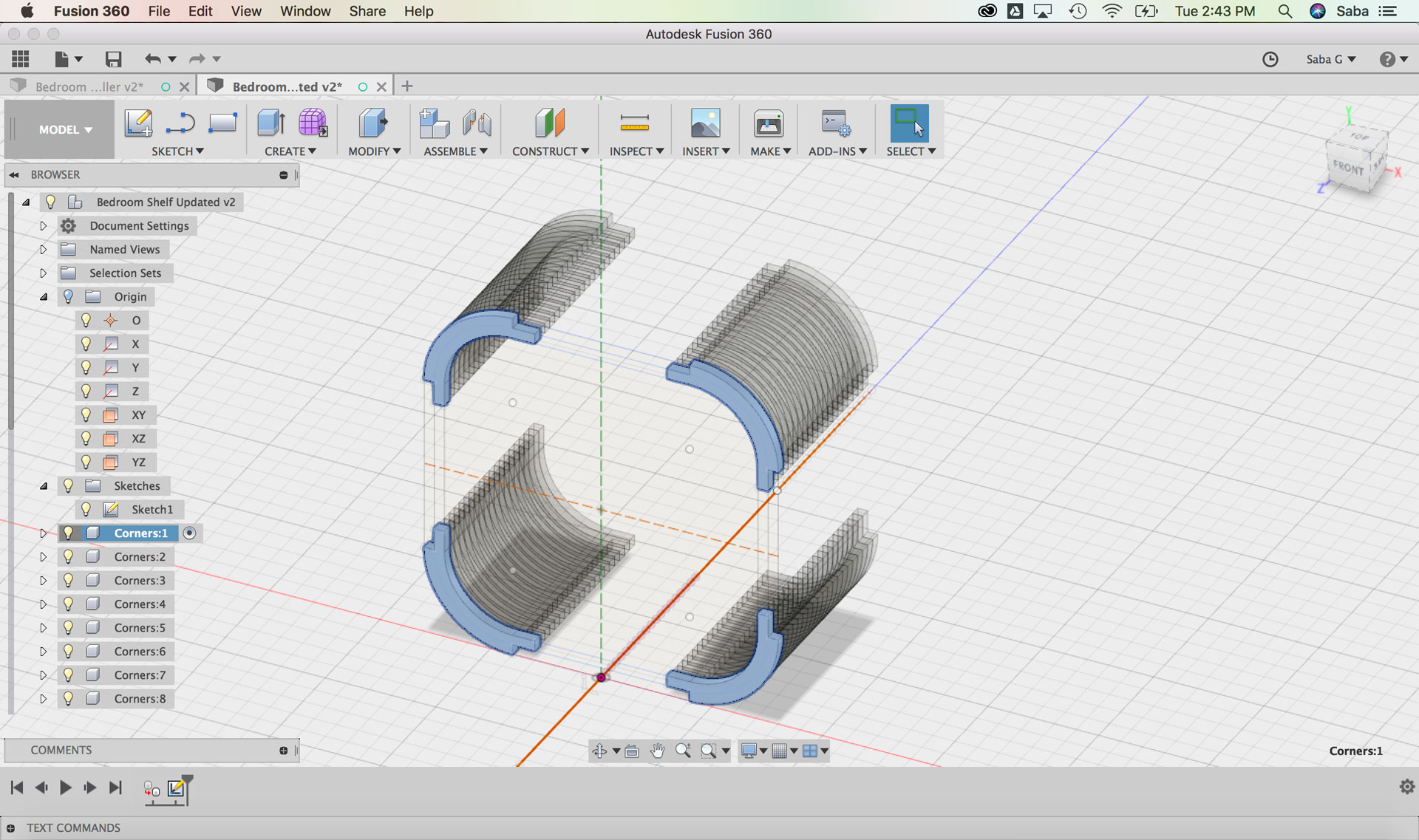
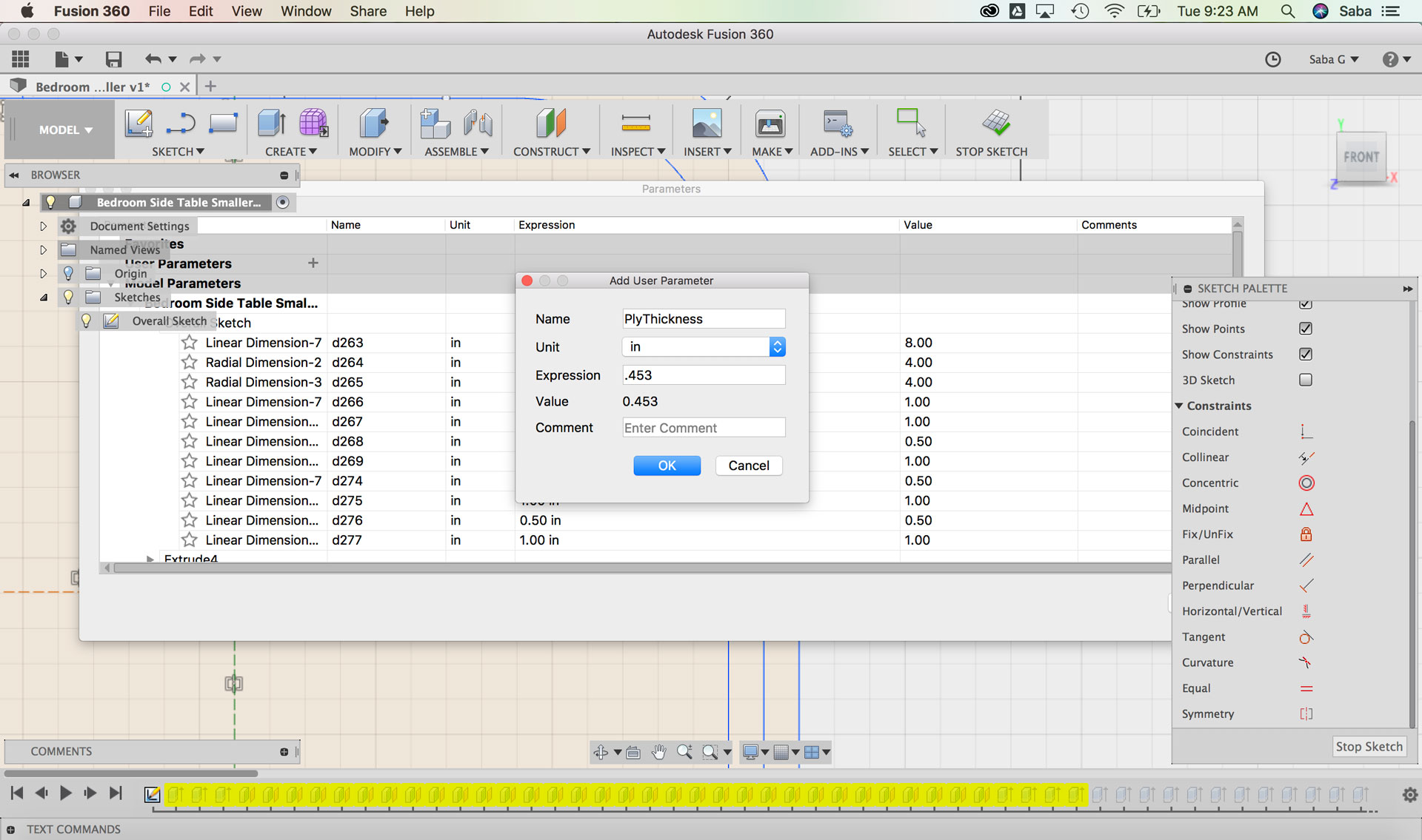
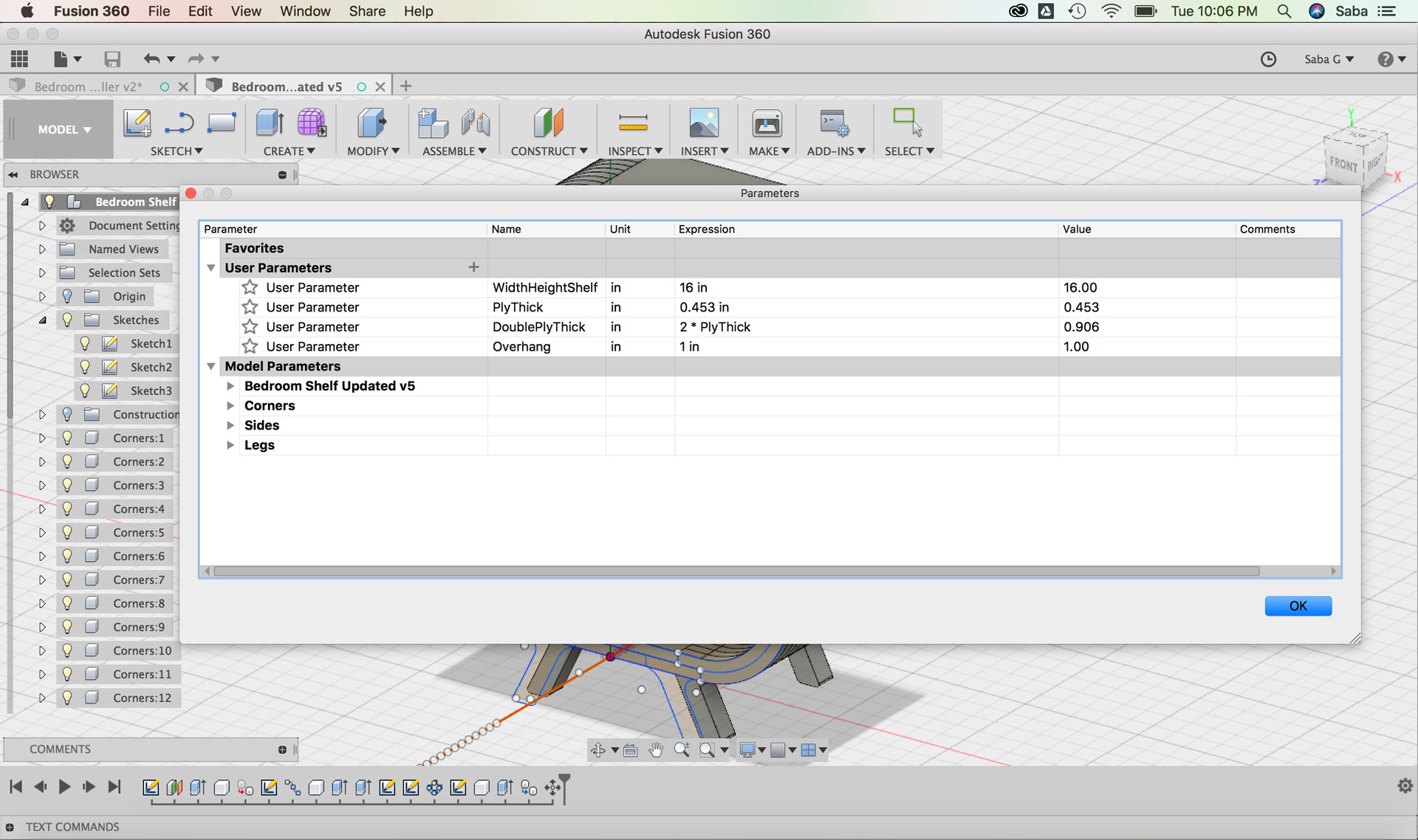
I realized while designing the second iteration that there was an easier way to model the unit using parameters, mirroring/copying components, and using components, in case I wanted to modify the design and depth of the plywood in the future. Although I spent days modeling these various iterations and design options, all the time I spent helped me become a better Fusion 360 modeler (woohoo, looking at the bright side of the many 2am nights...or mornings :)).
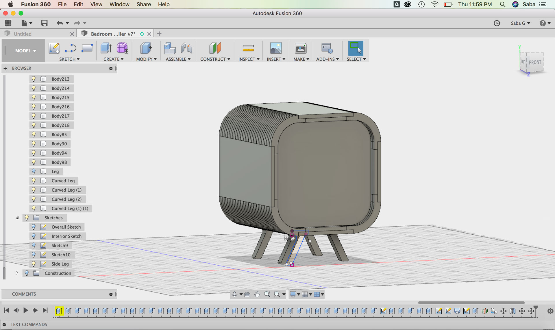
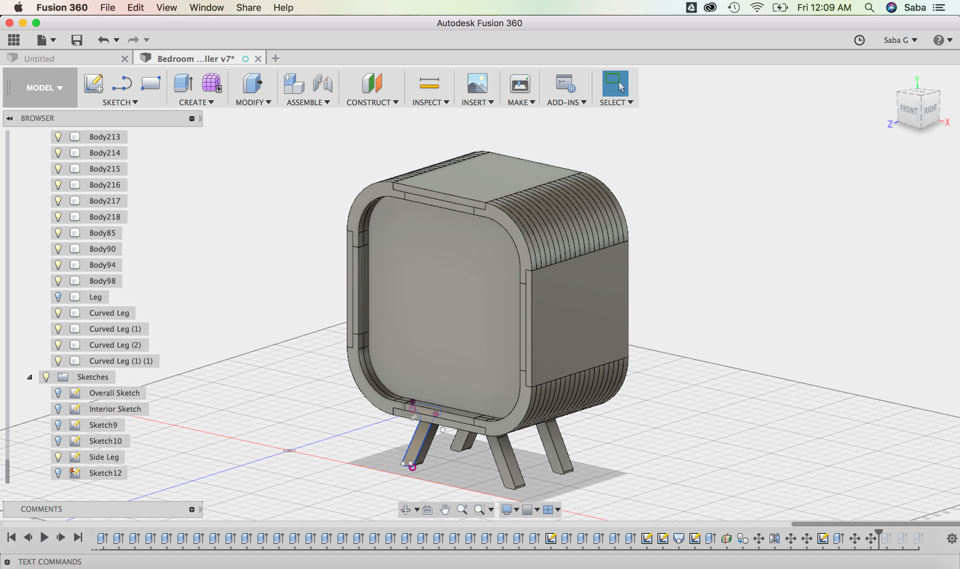
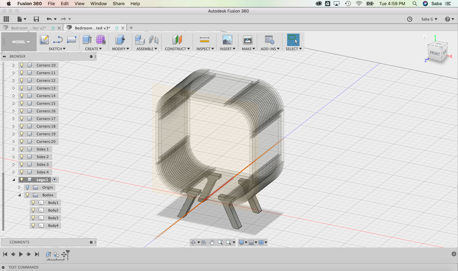
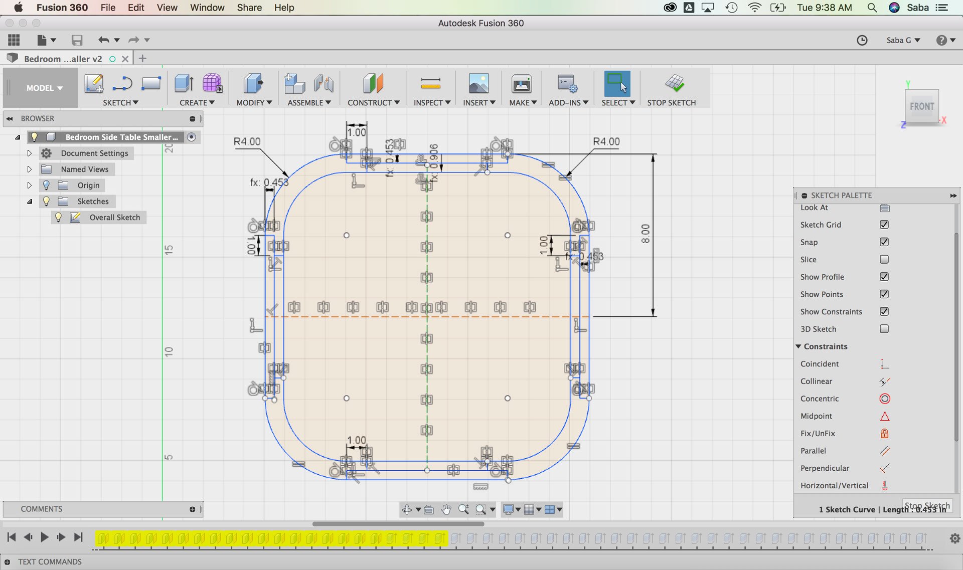
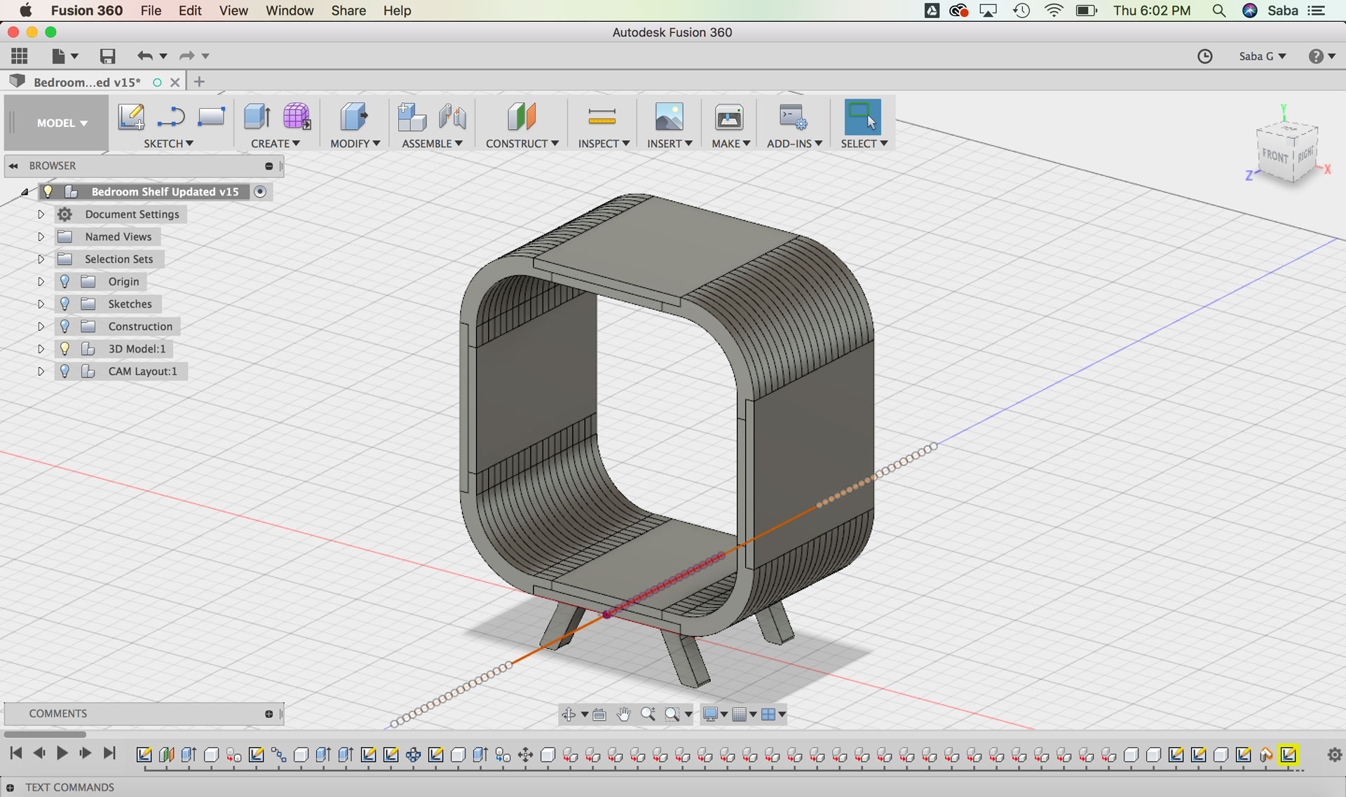
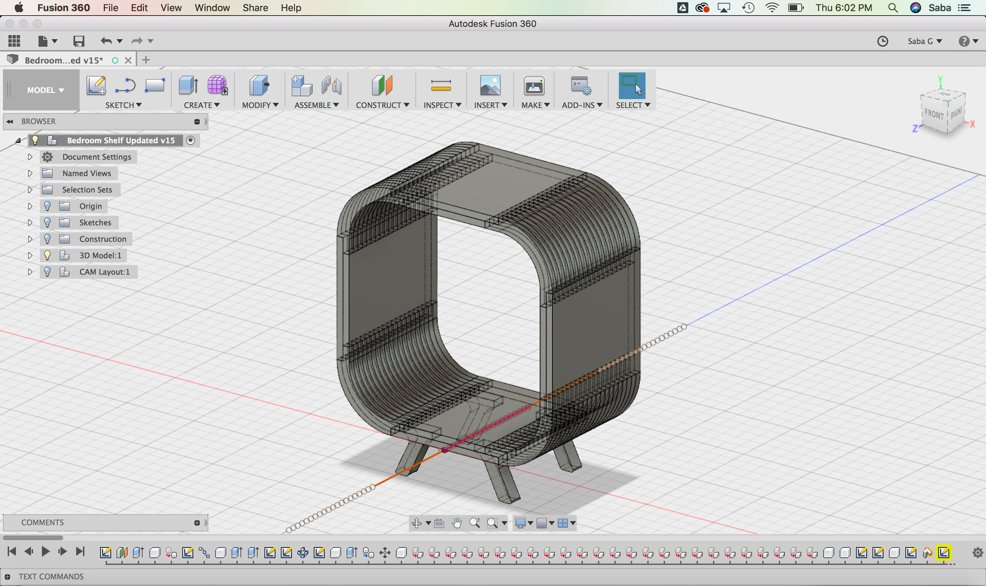
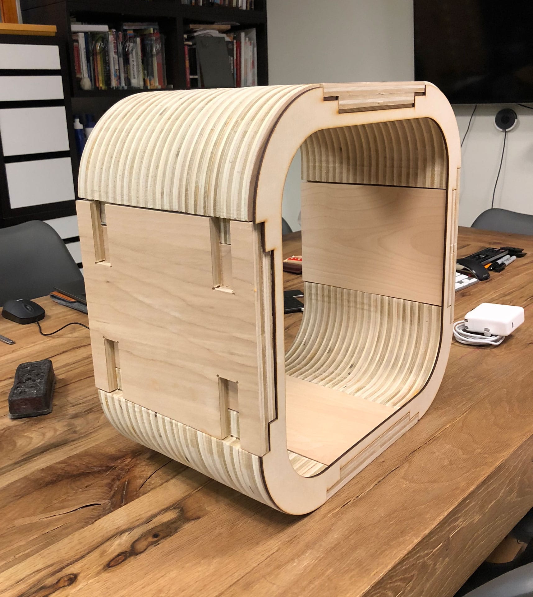
My final iteration for the shelf design has dimensions of 16”W x 16”H x 10”D for the main casing with legs around 3” high off the ground.
I did a few test runs on the milling machine at our studio (NuVu) to understand the process of milling from Fusion 360. I cut a simple semi-circular table that we needed for our upcoming exhibition that one of our NuVu students had designed.
Once I had an understanding of the basic process, it was time for cutting my interactive shelf. Whew (deep breath). Here we go.
CAM Setup
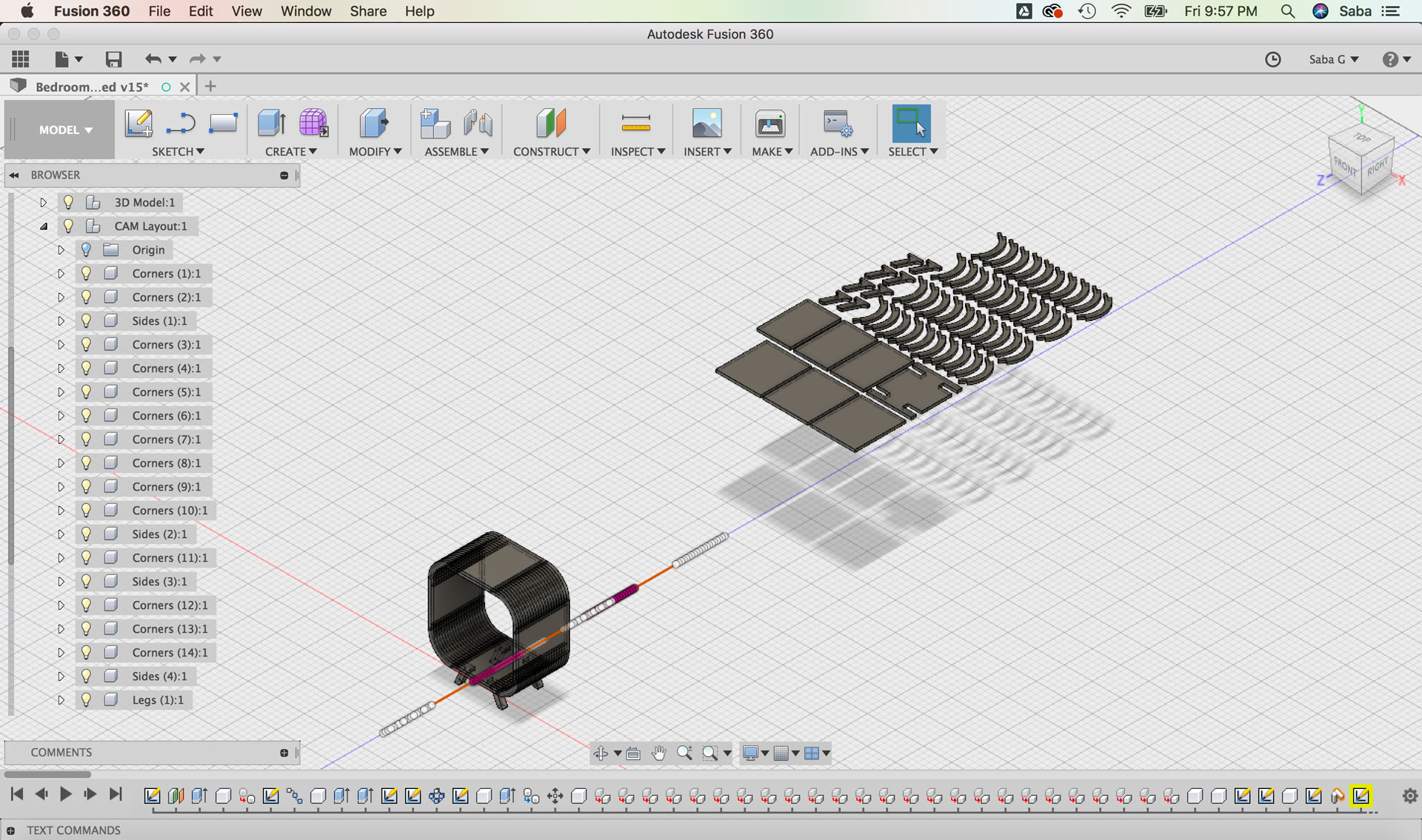
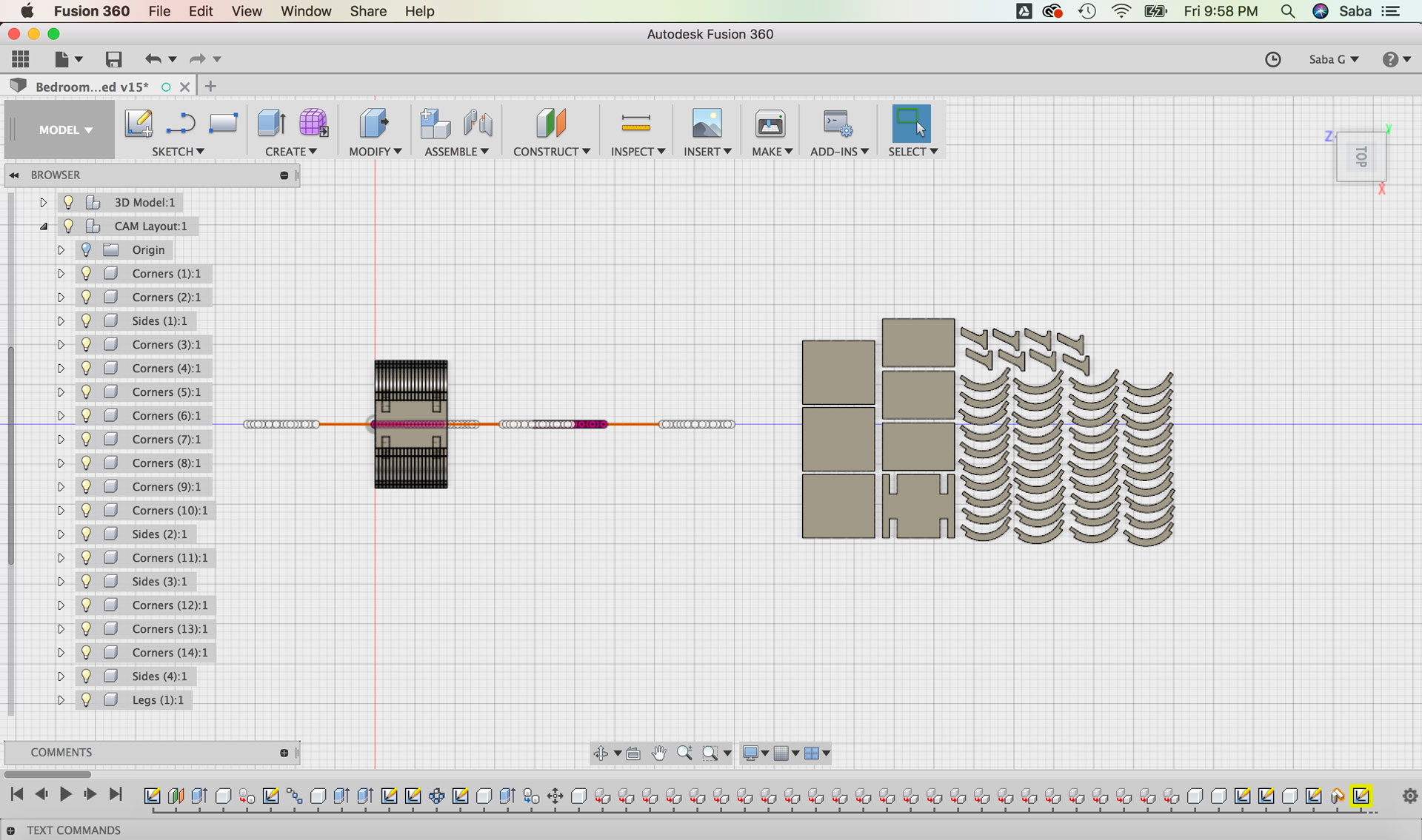
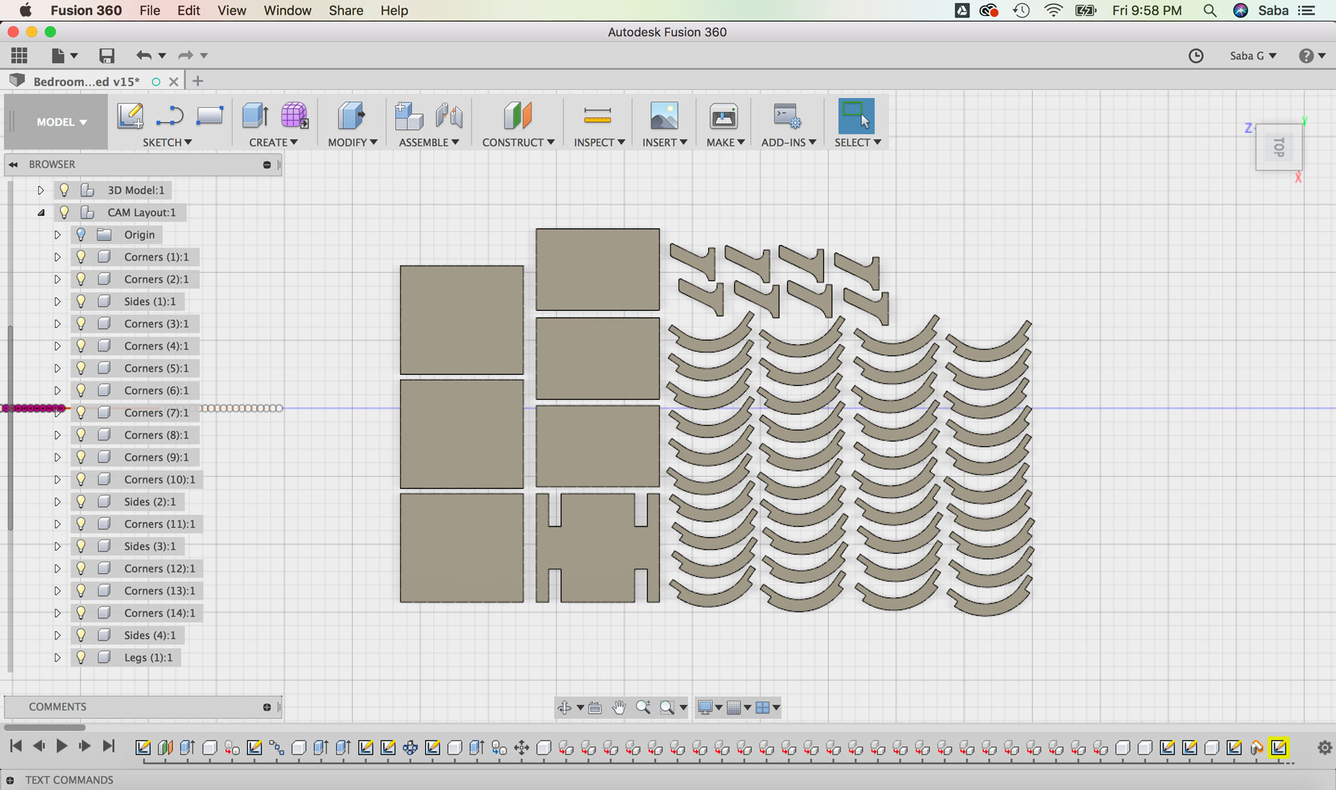
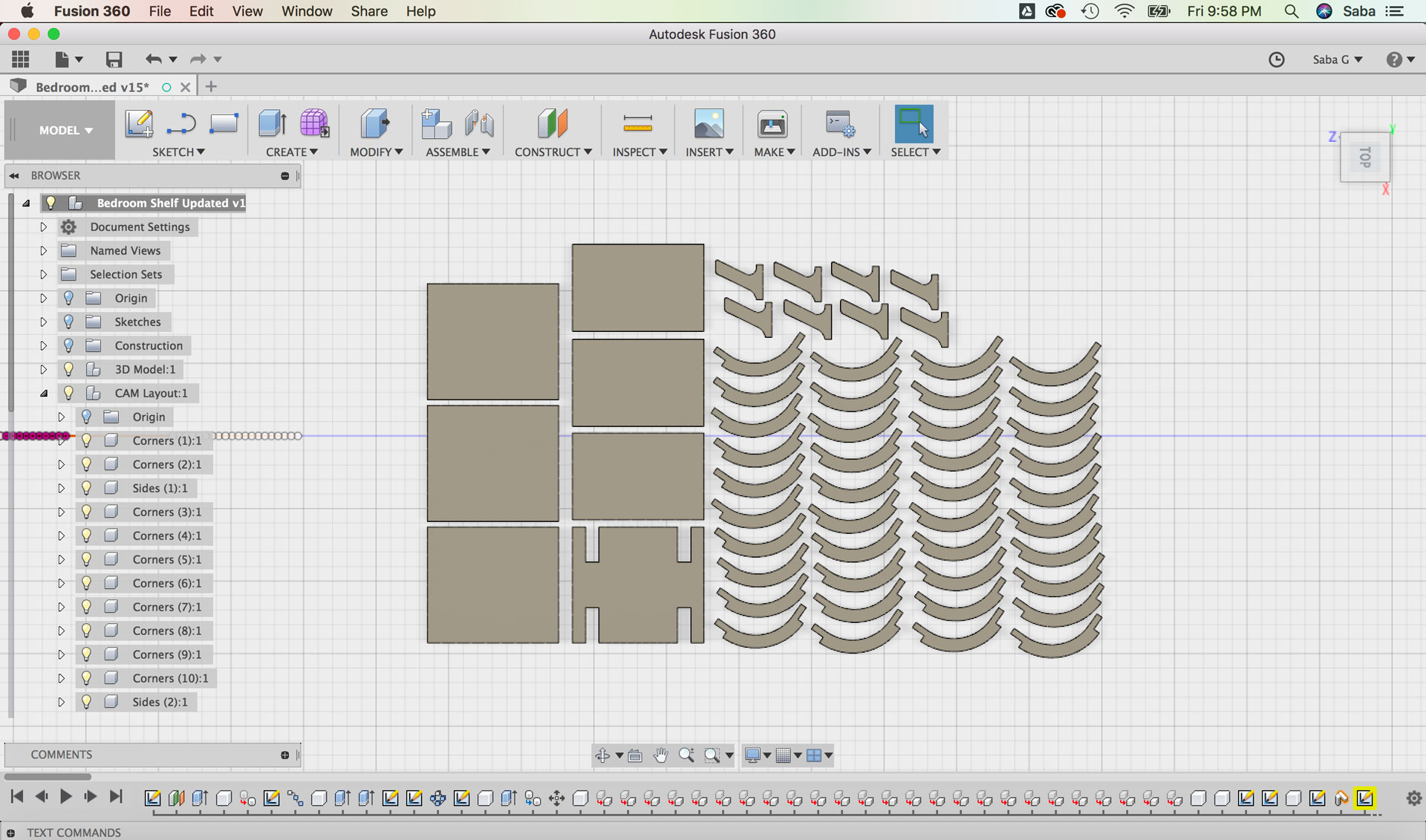
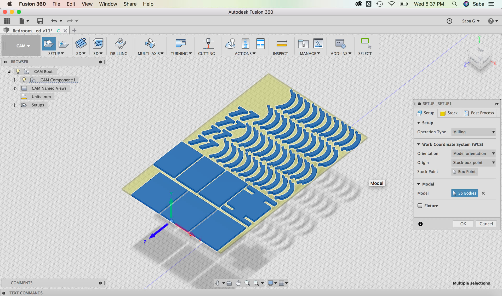
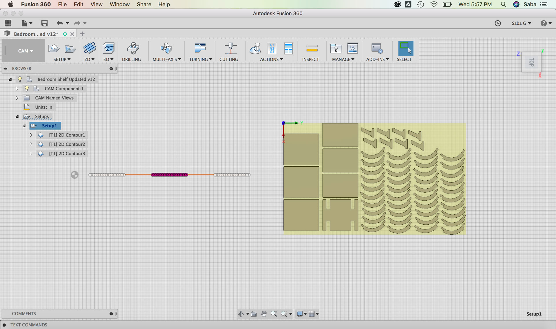
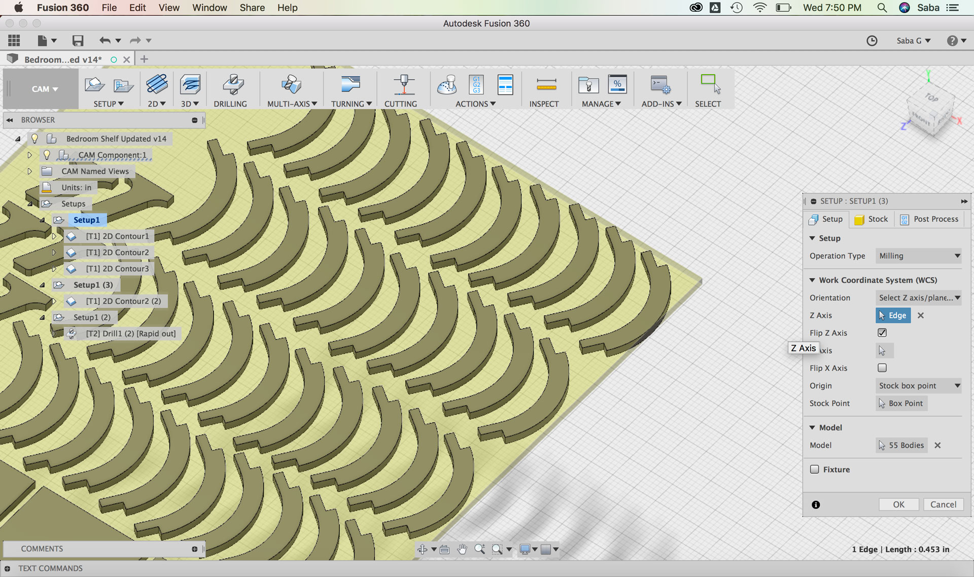
I decided to use the CAM features in Fusion 360 to set up my tool paths for machining the pieces of my shelf. Before I could do this, I needed to lay all my pieces flat on the x-y plane. In order to do this, I copied and pasted the 3D Model Component and called it CAM Layout. I then used the “Align” command under the Modify tool to align the bodies flat and close to one another as to not waste too much material.
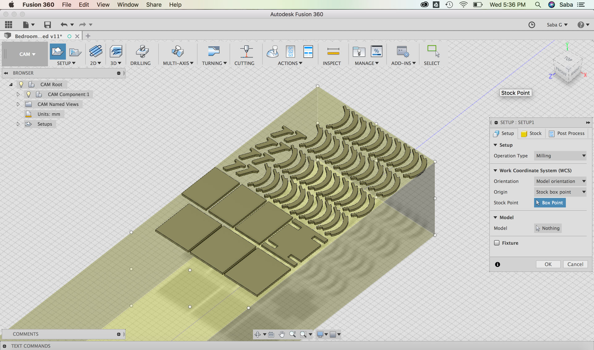
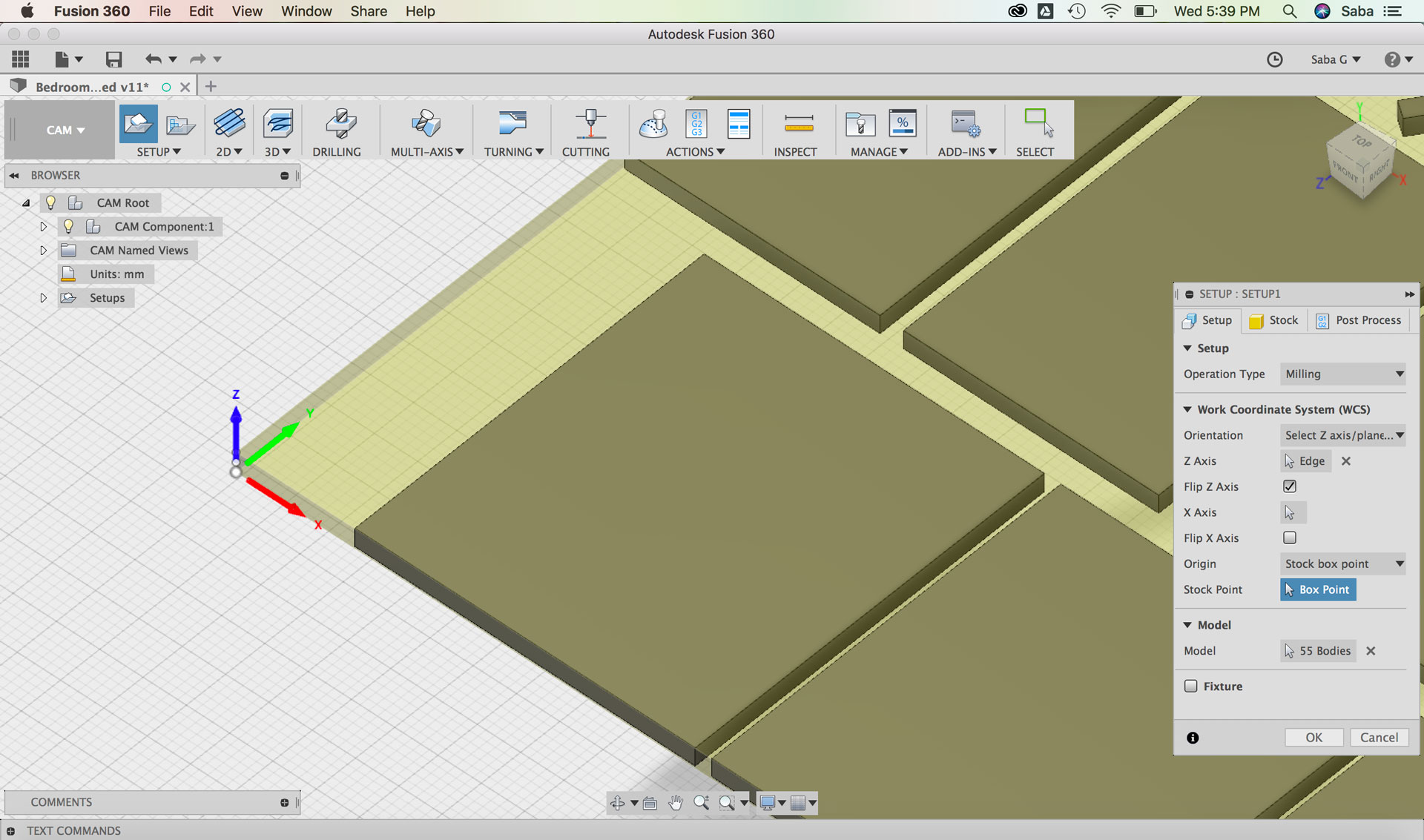
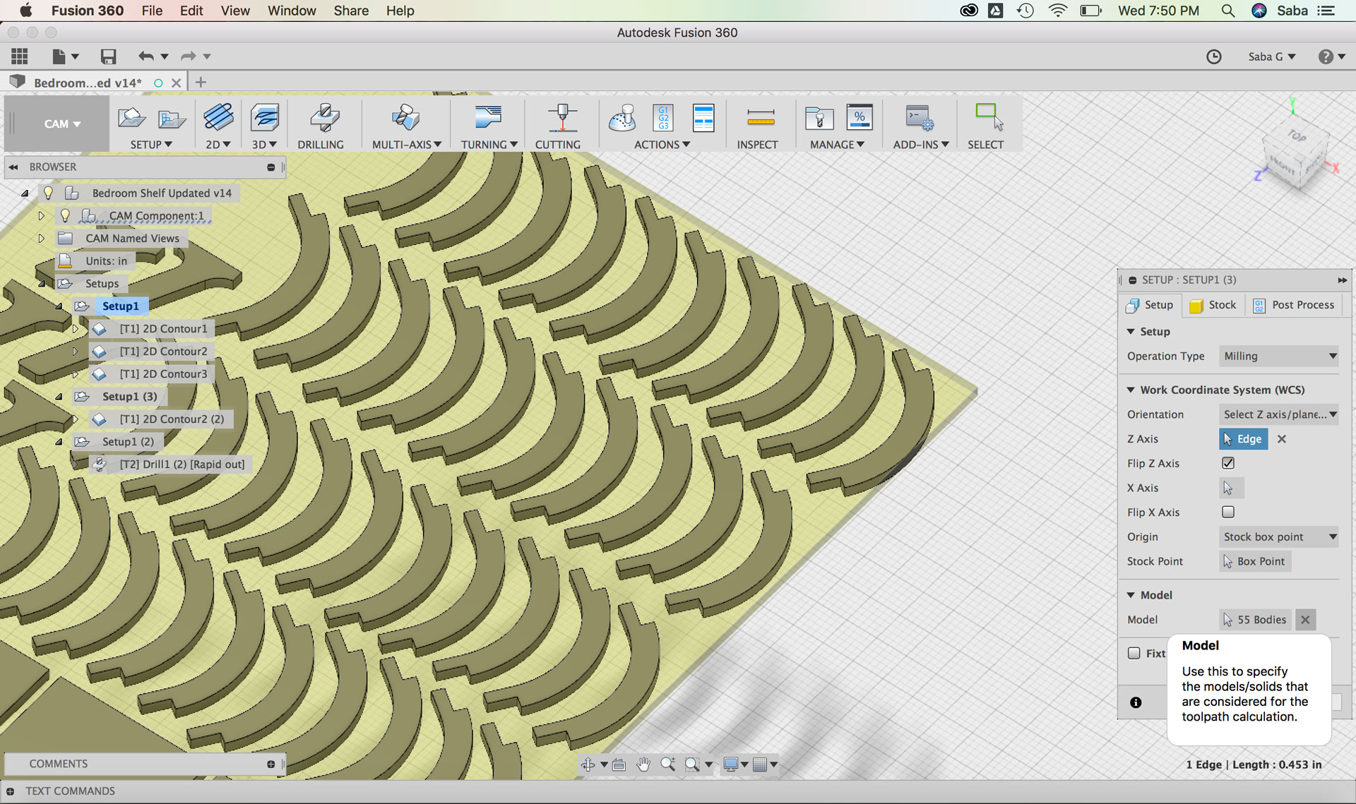
I began by creating a new Setup in the “CAM” menu in Fusion and did the following steps:
Under Setup tab:
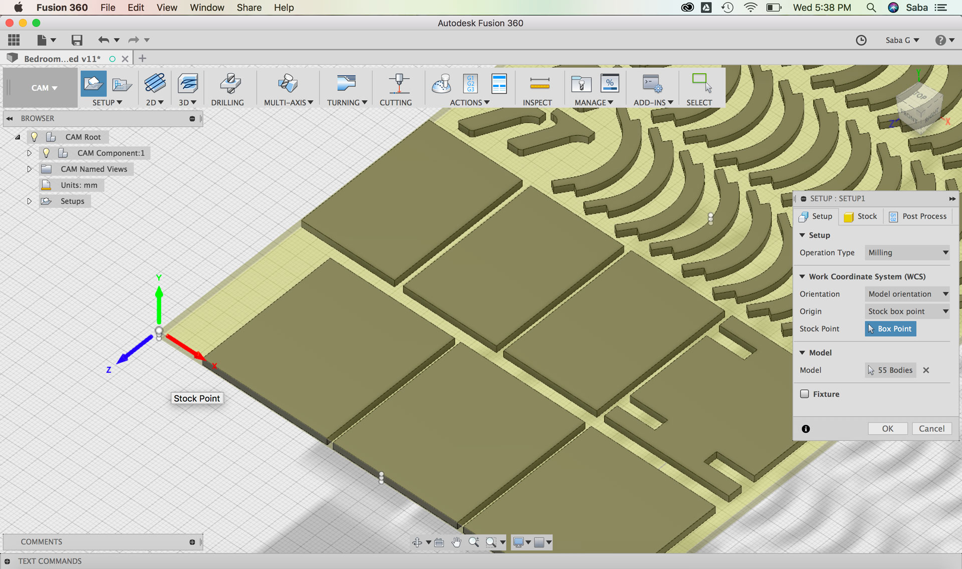
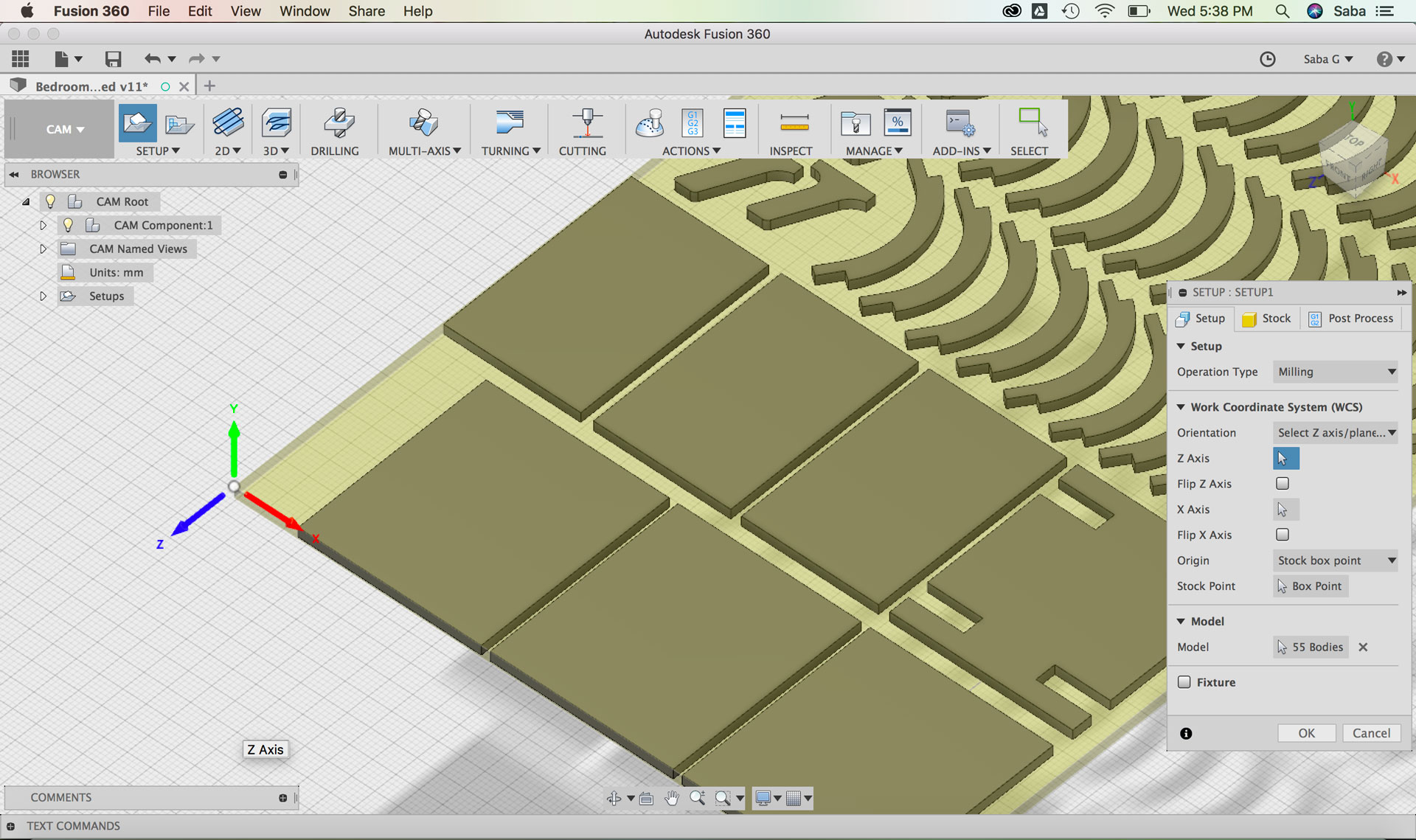
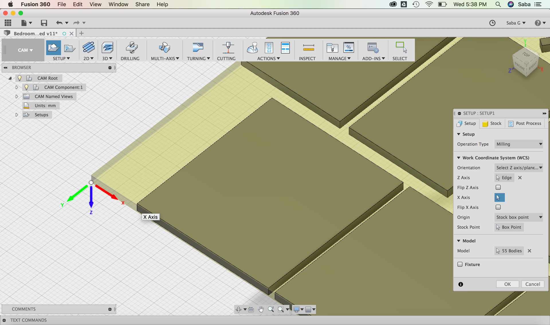
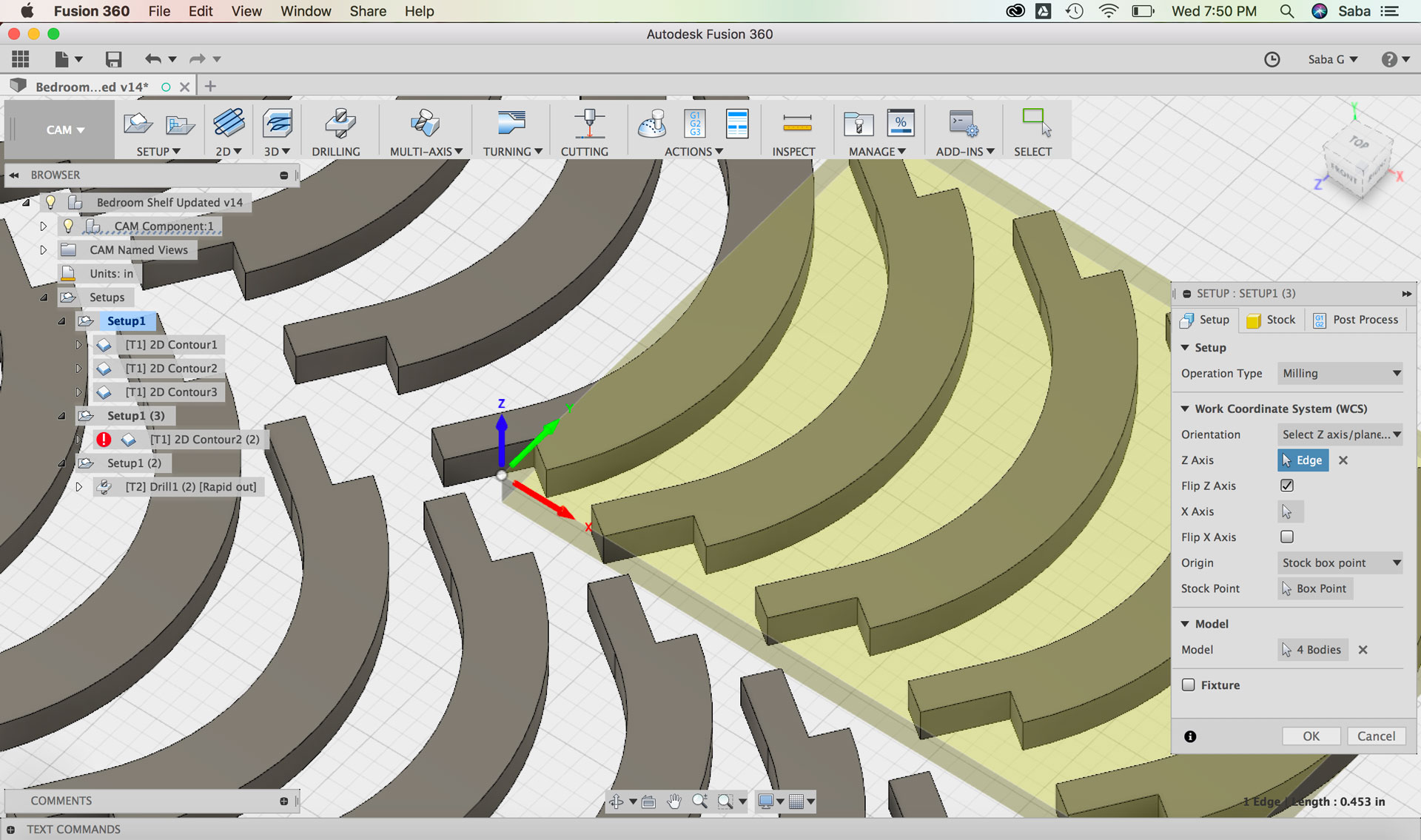
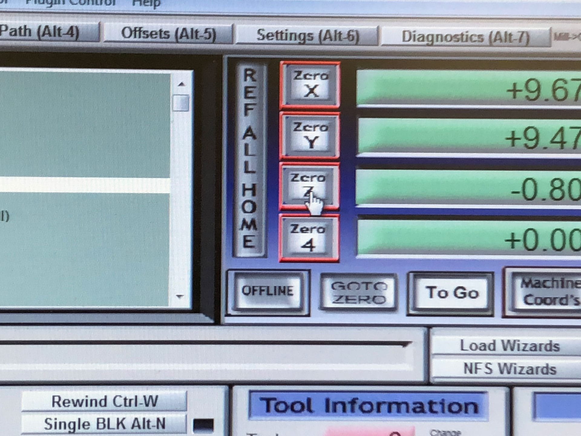
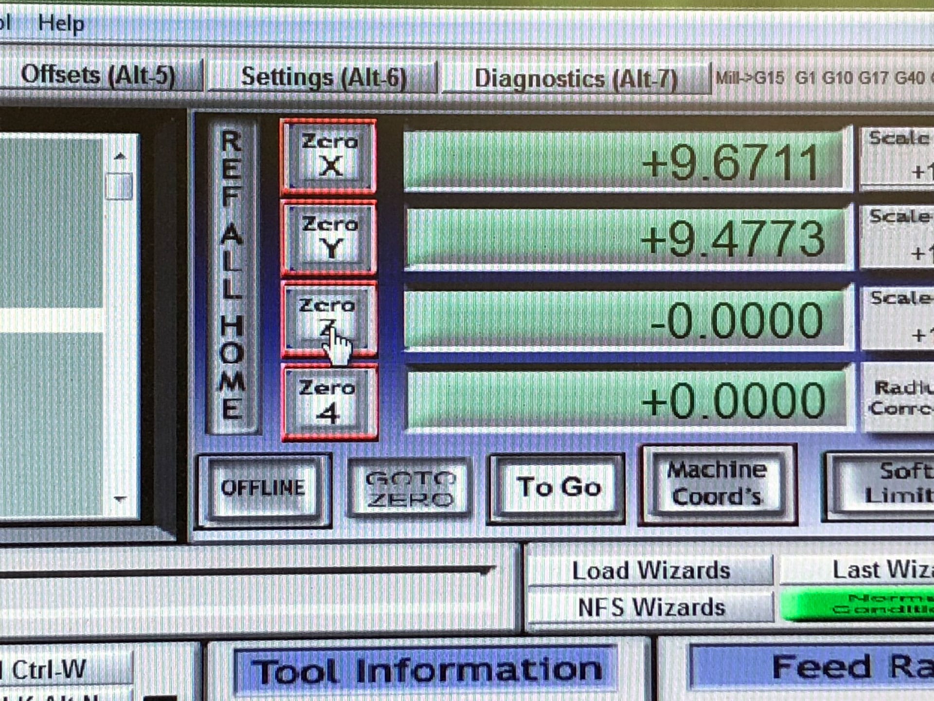
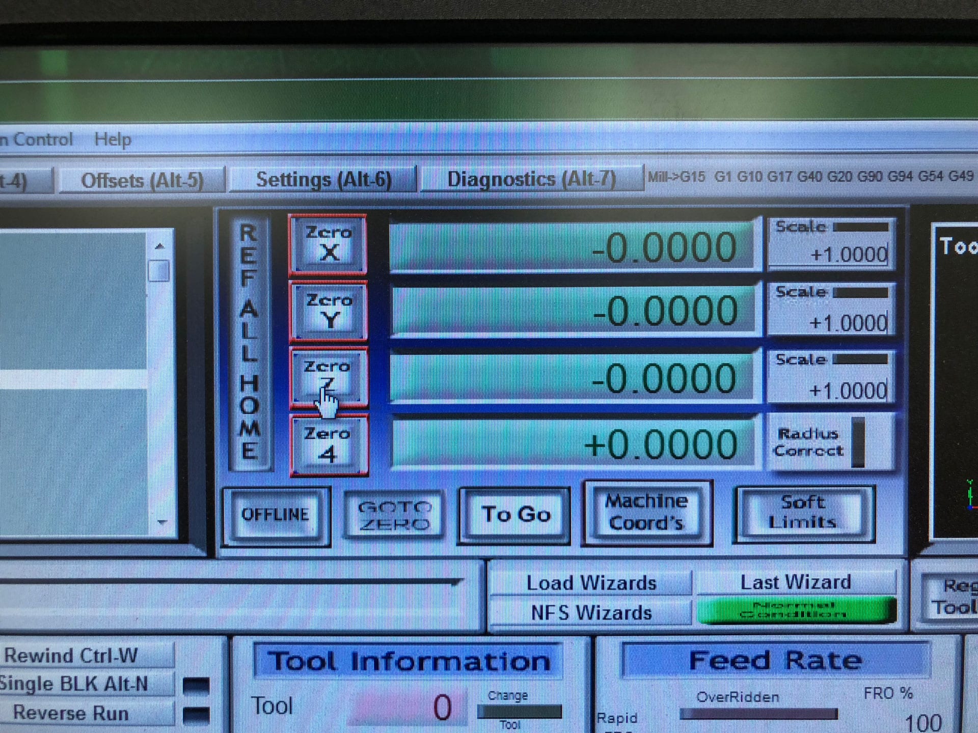
Update Work Coordinate System based on the x, y, z axis of our milling machine at NuVu
Select Stock Point (top of stock material at the bottom left corner of my stock material)
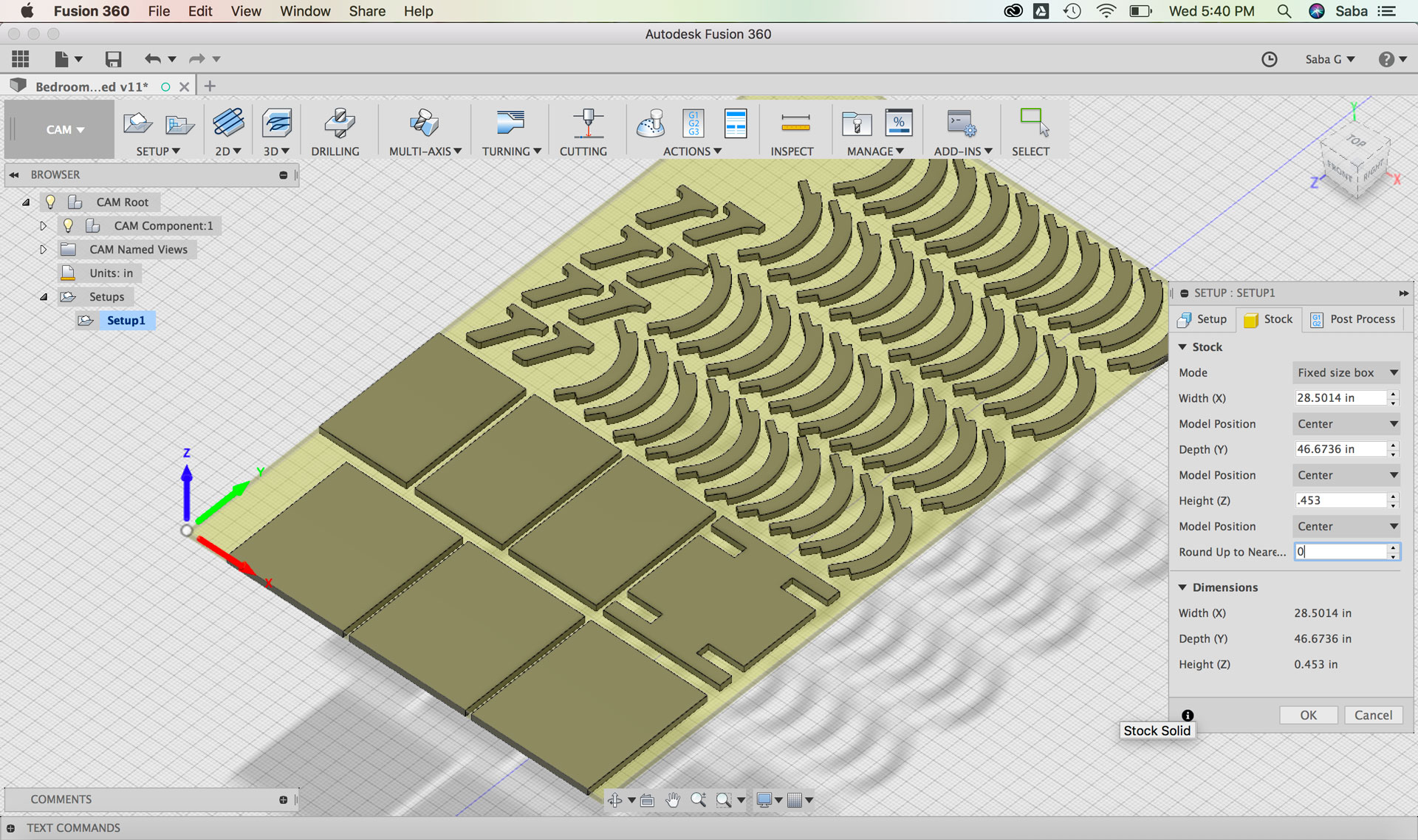
Under Stock tab:
Set Mode to “Fixed size box”
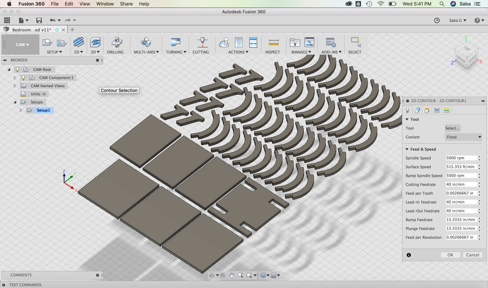
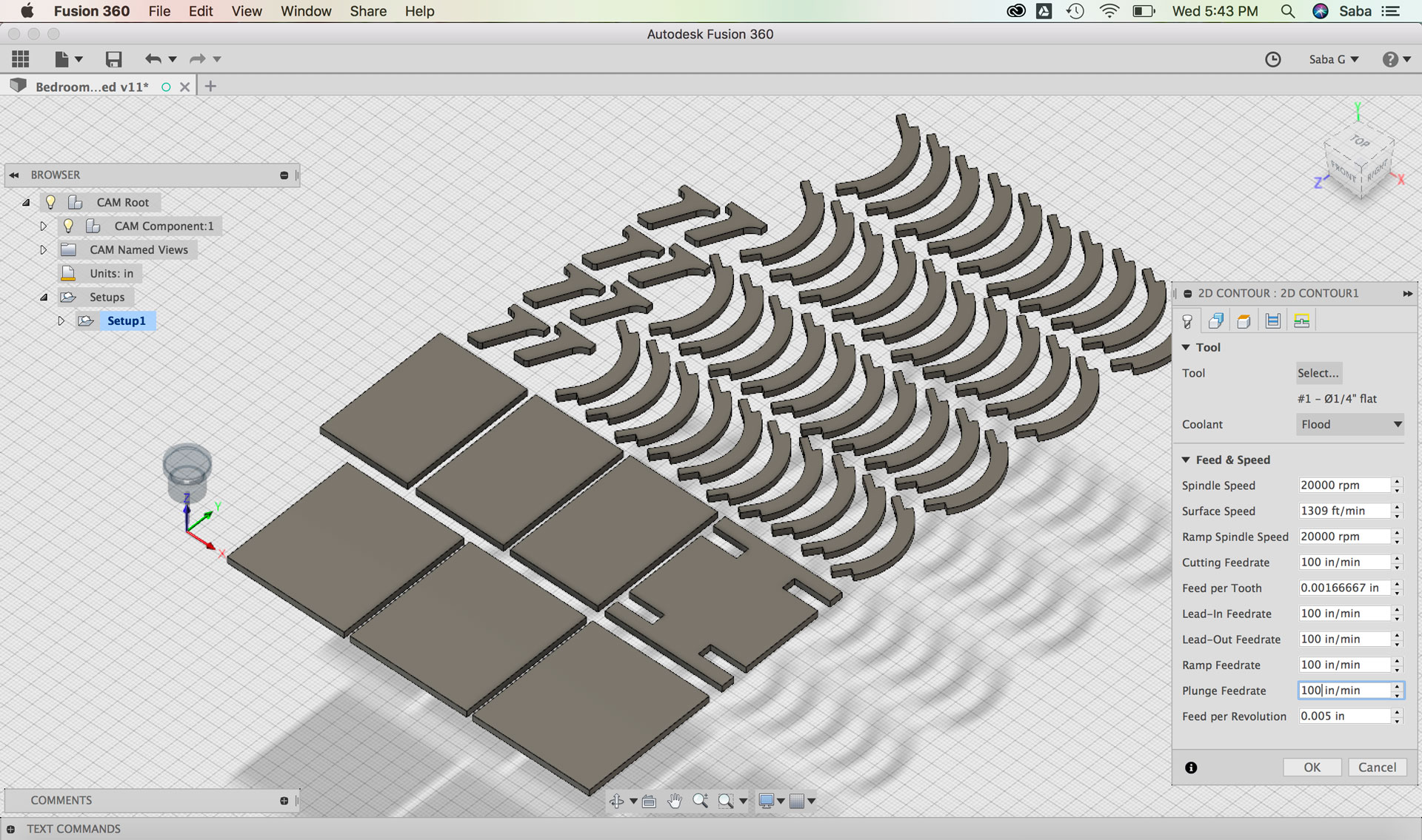
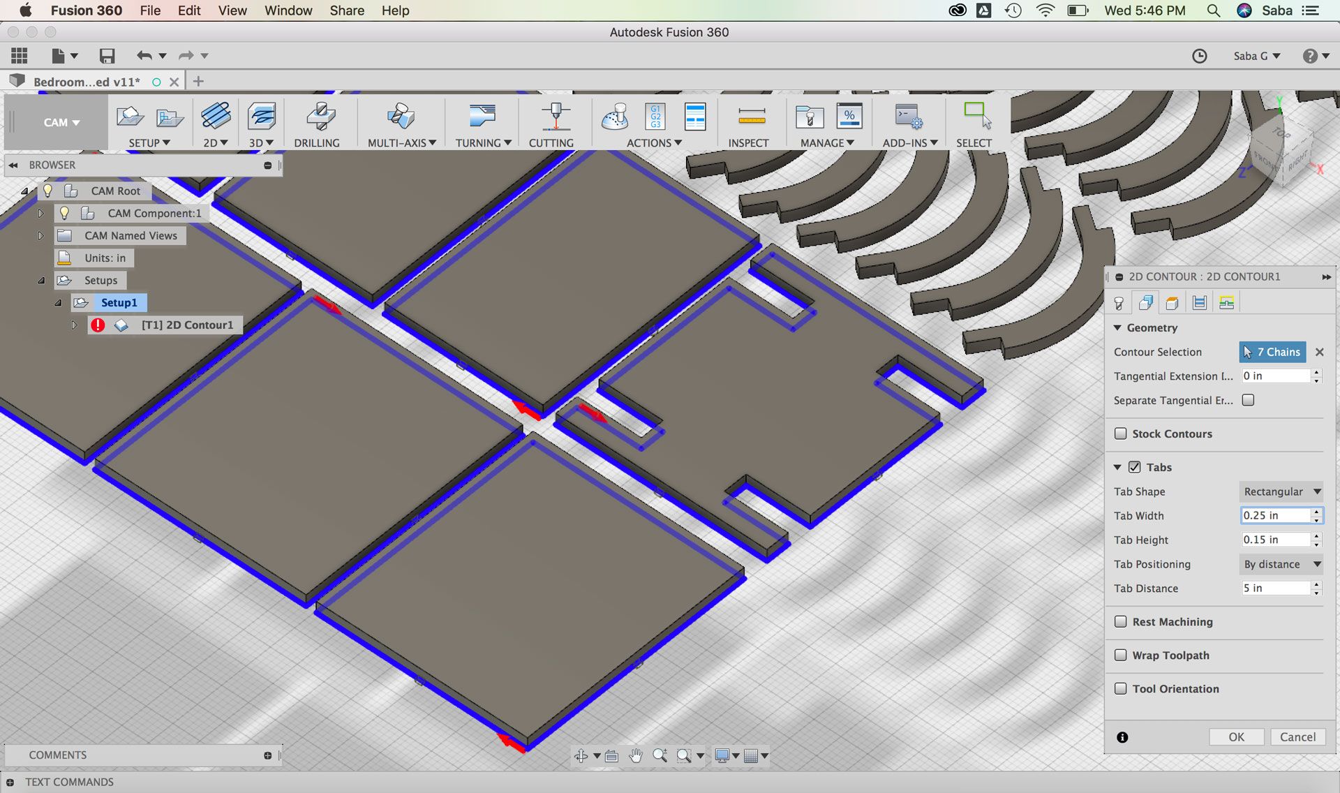
For my first toolpath, I used the 2D Contour feature and did the following steps for the rectangular pieces:
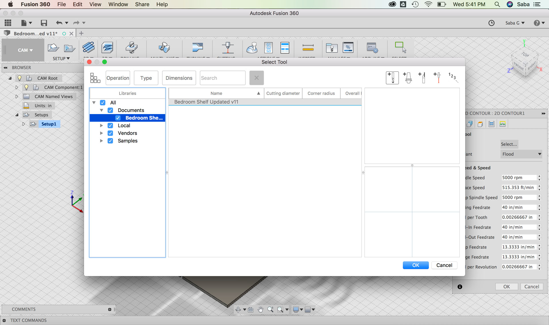
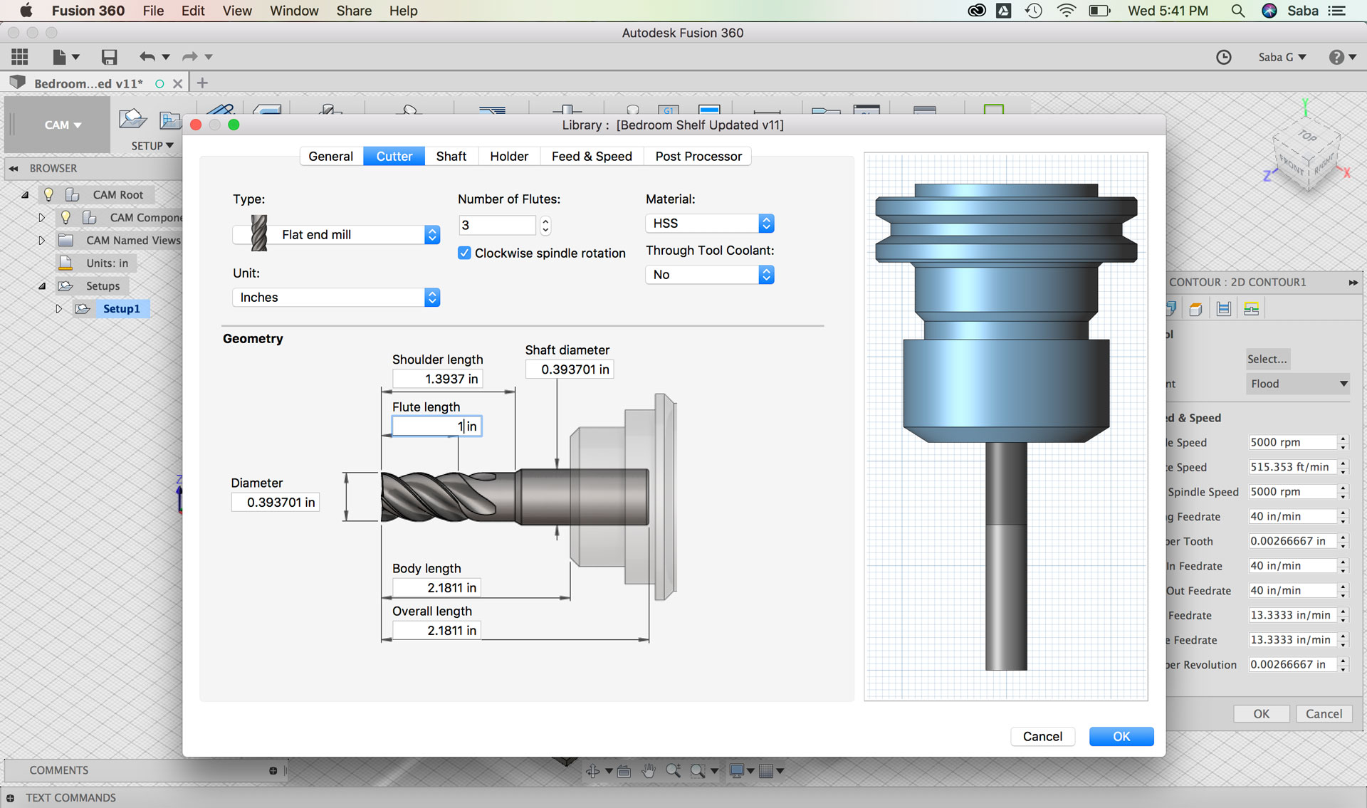
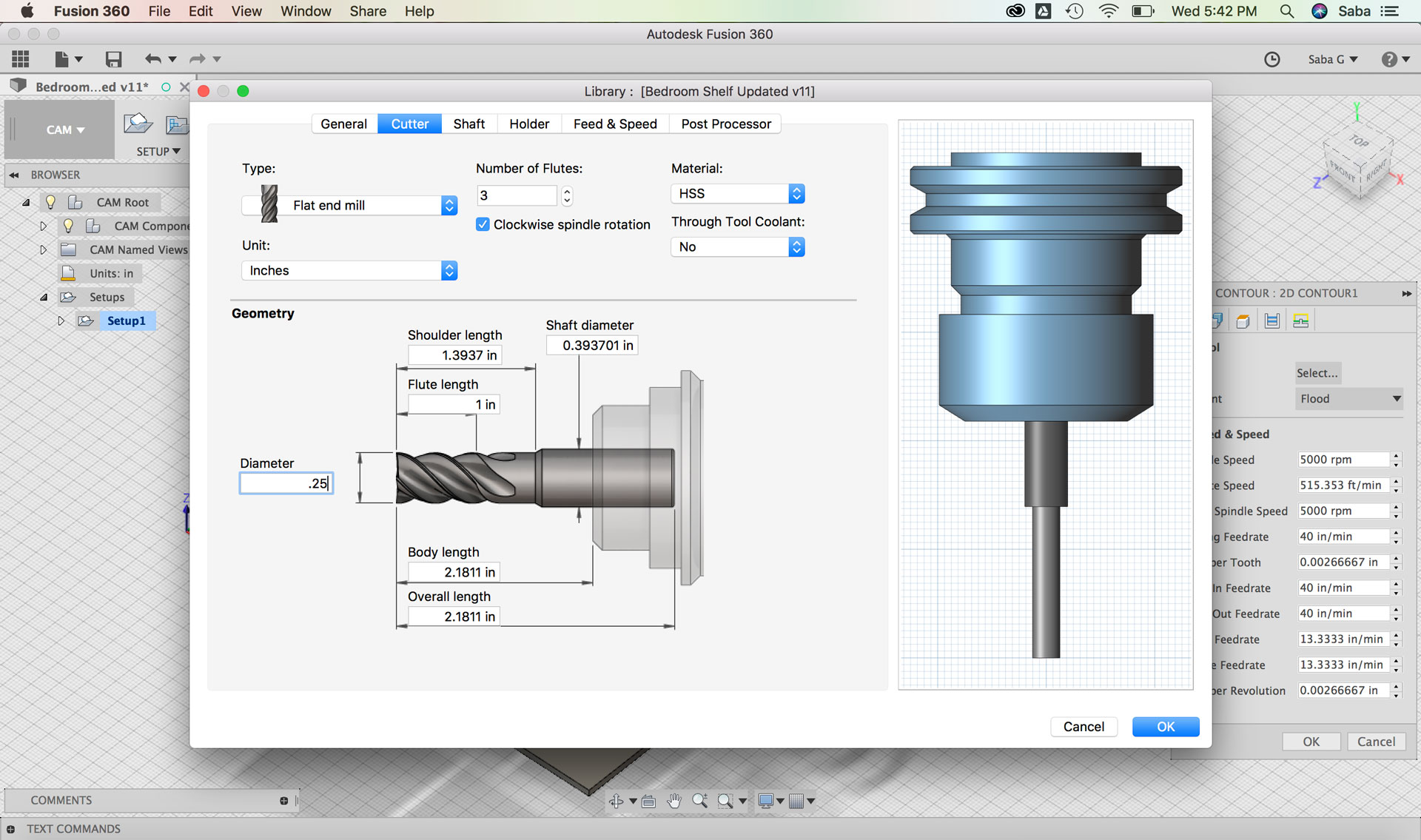
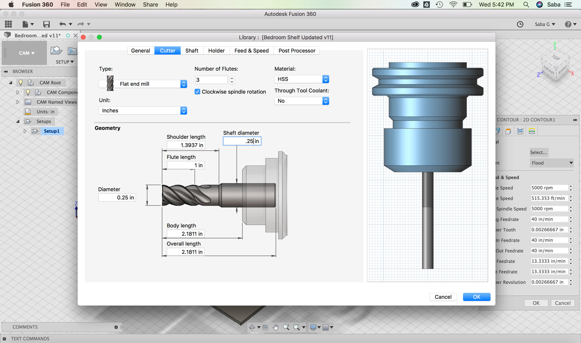
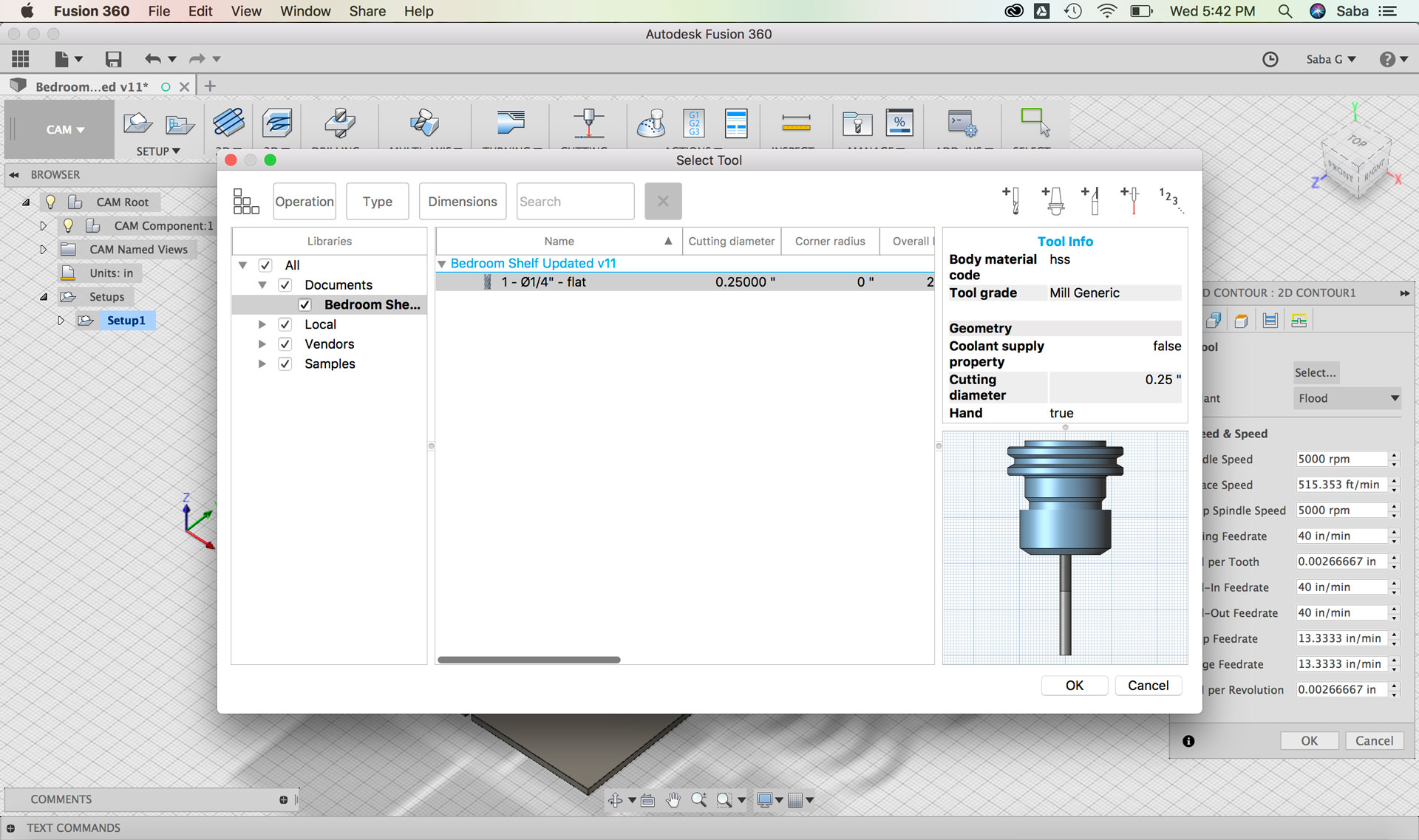
Under Tool tab:
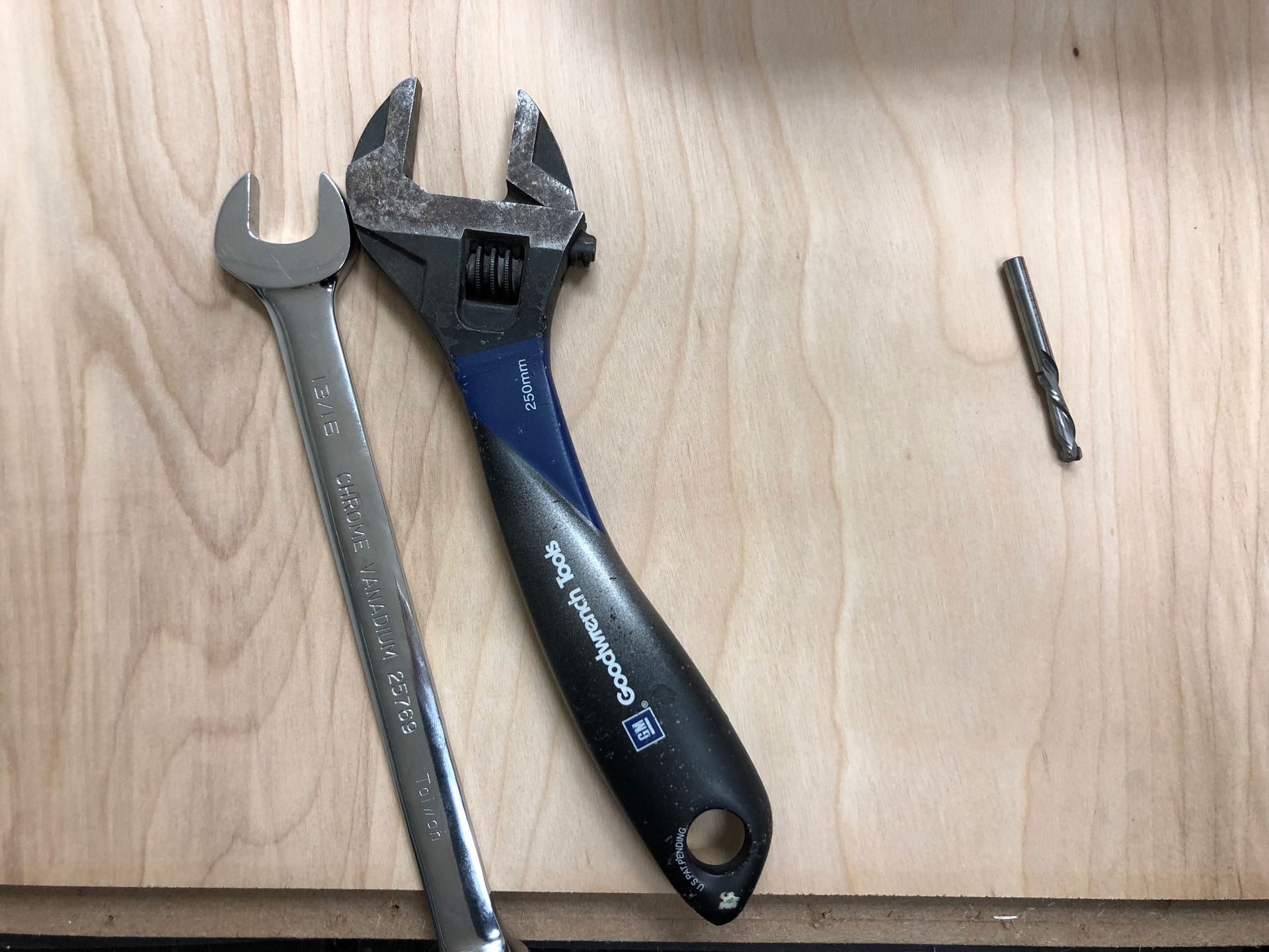
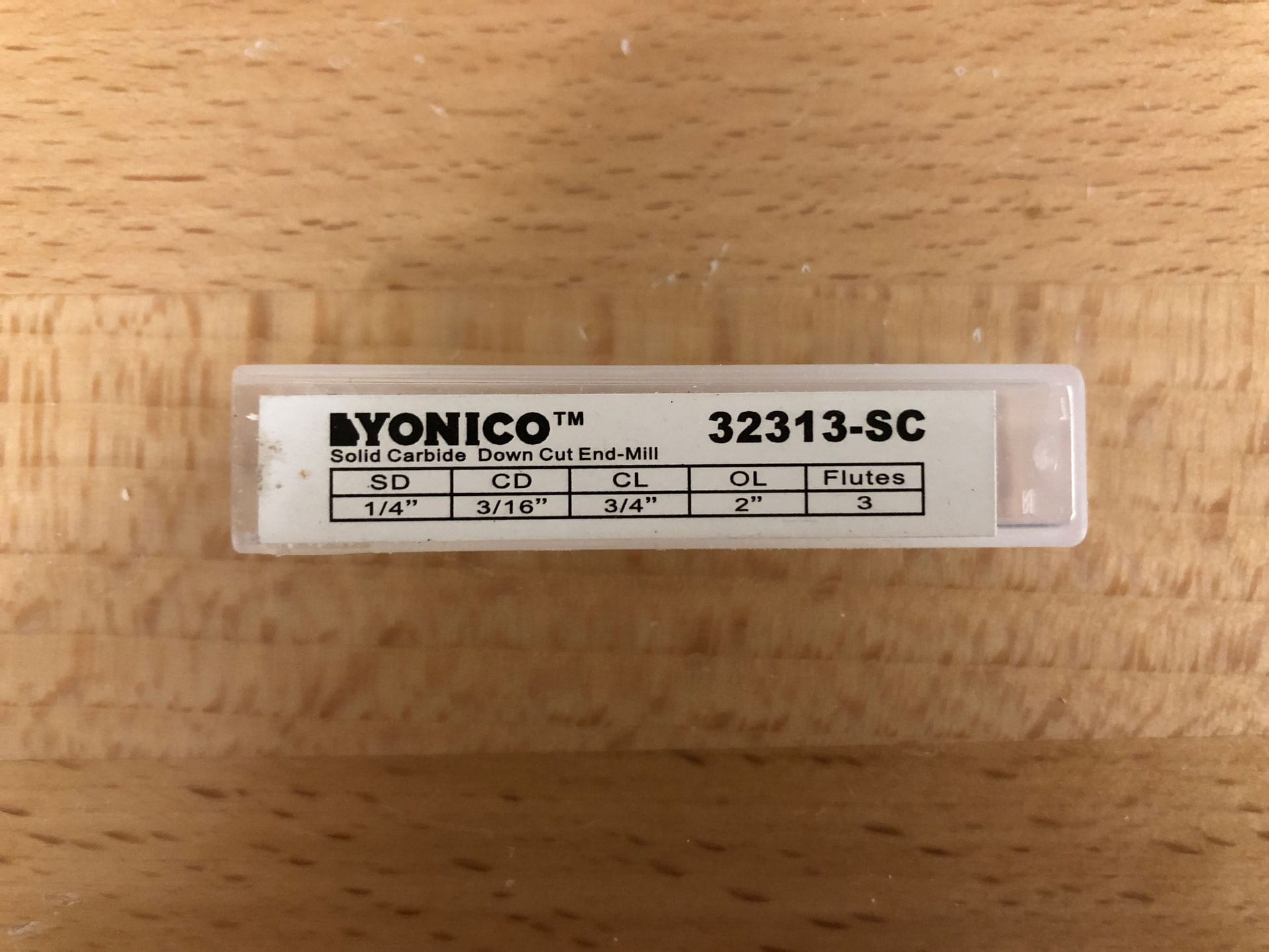
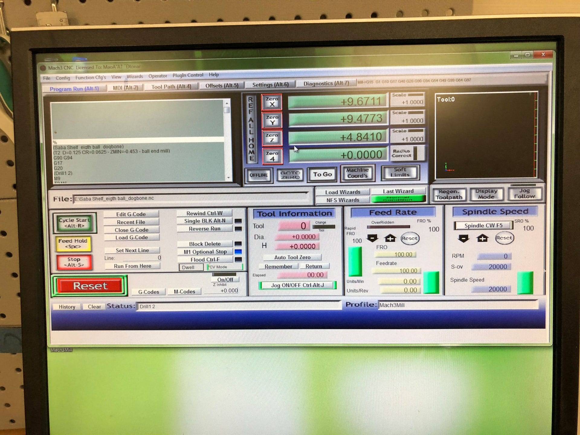
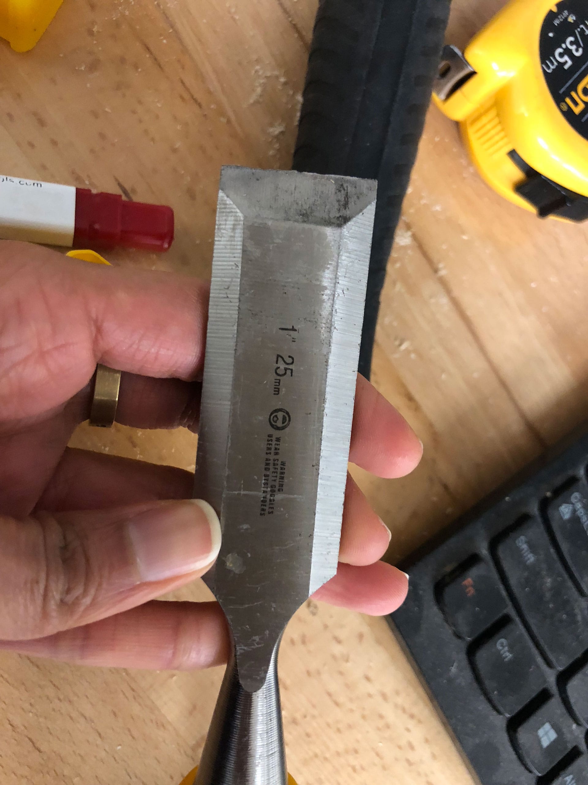
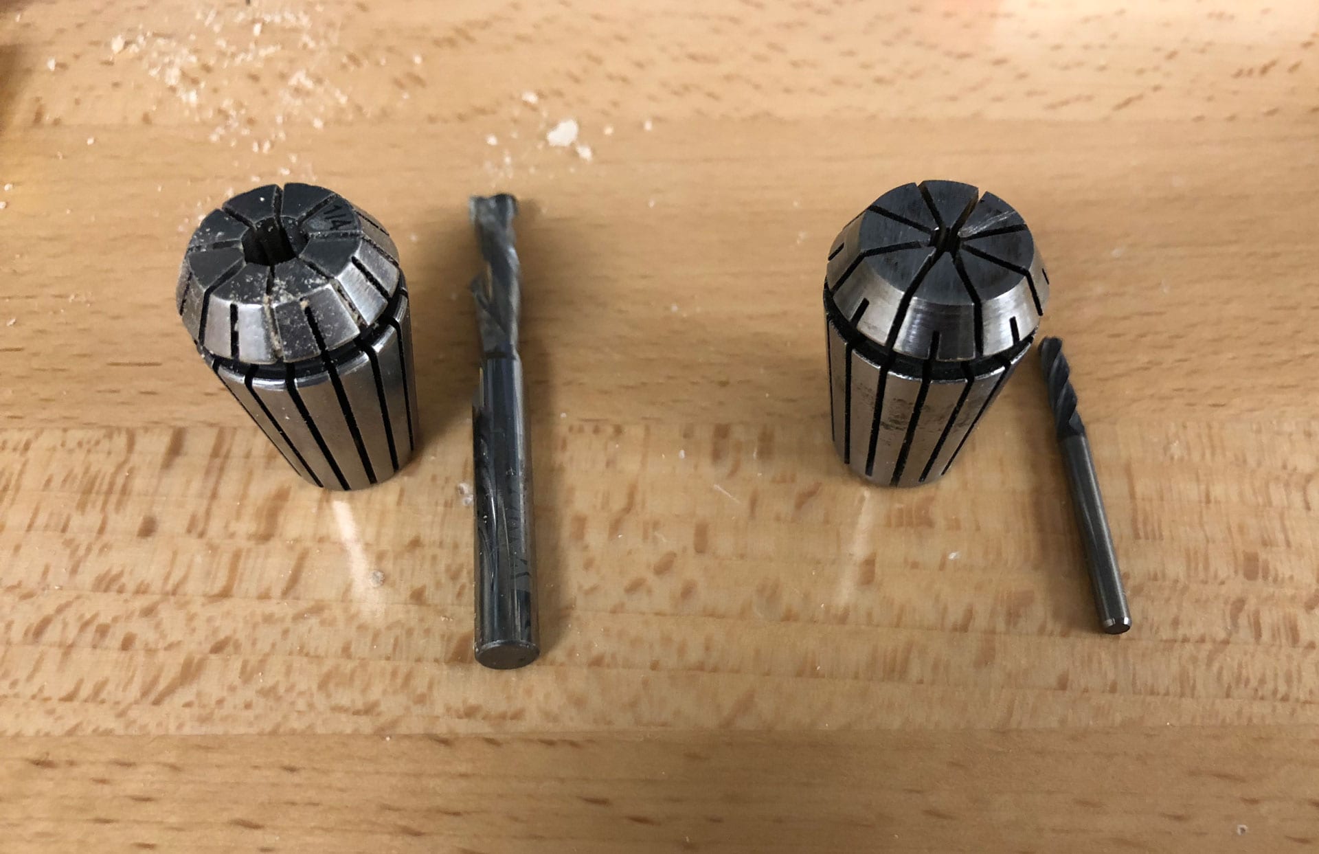
Select “Tool” >> add cutting tool >> Flat end mill, 3 Flutes, Flute Length of 1”, Shaft Diameter and Diameter of “.25,” Material made of HSS, and Units set to Inches
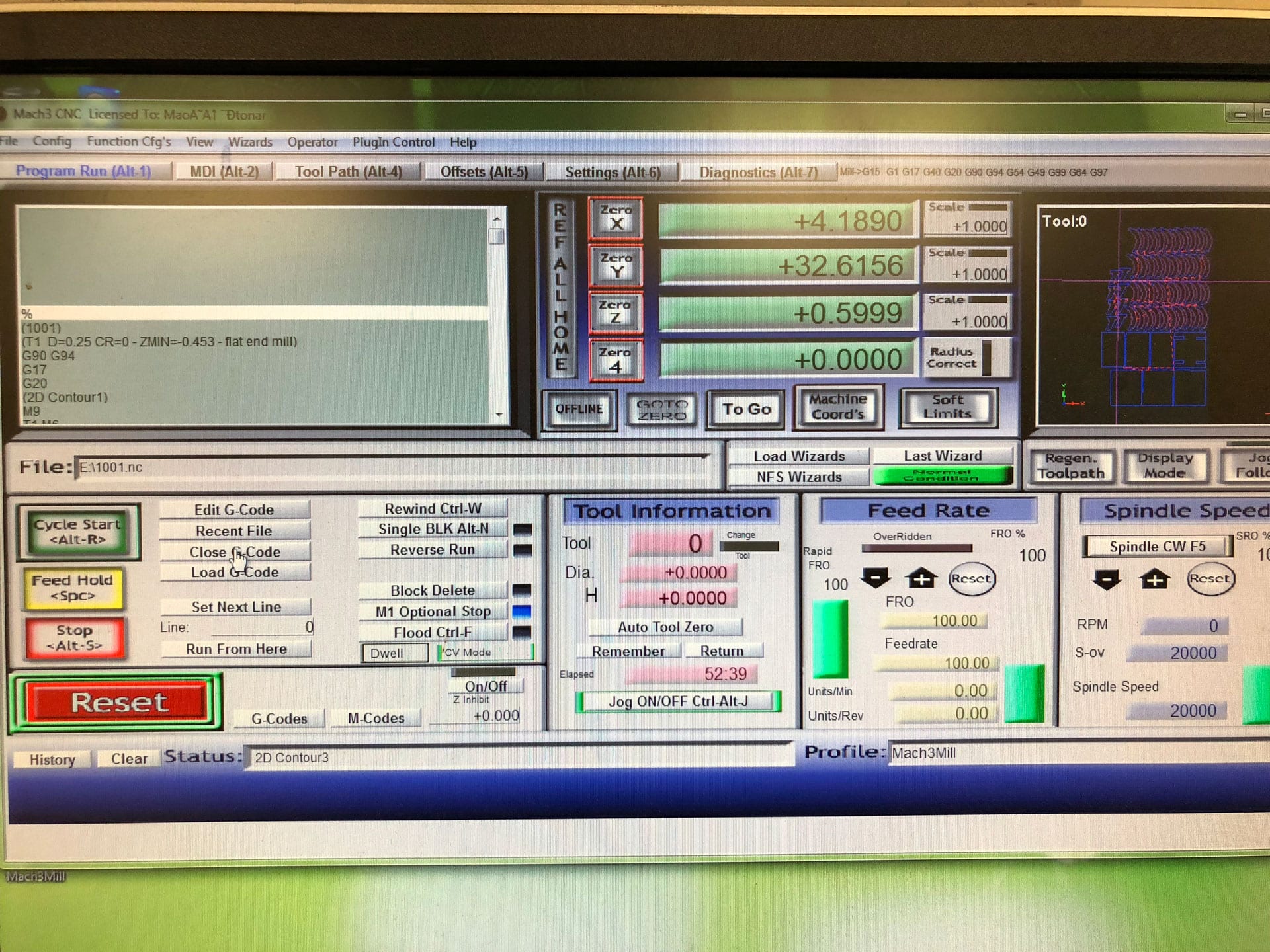
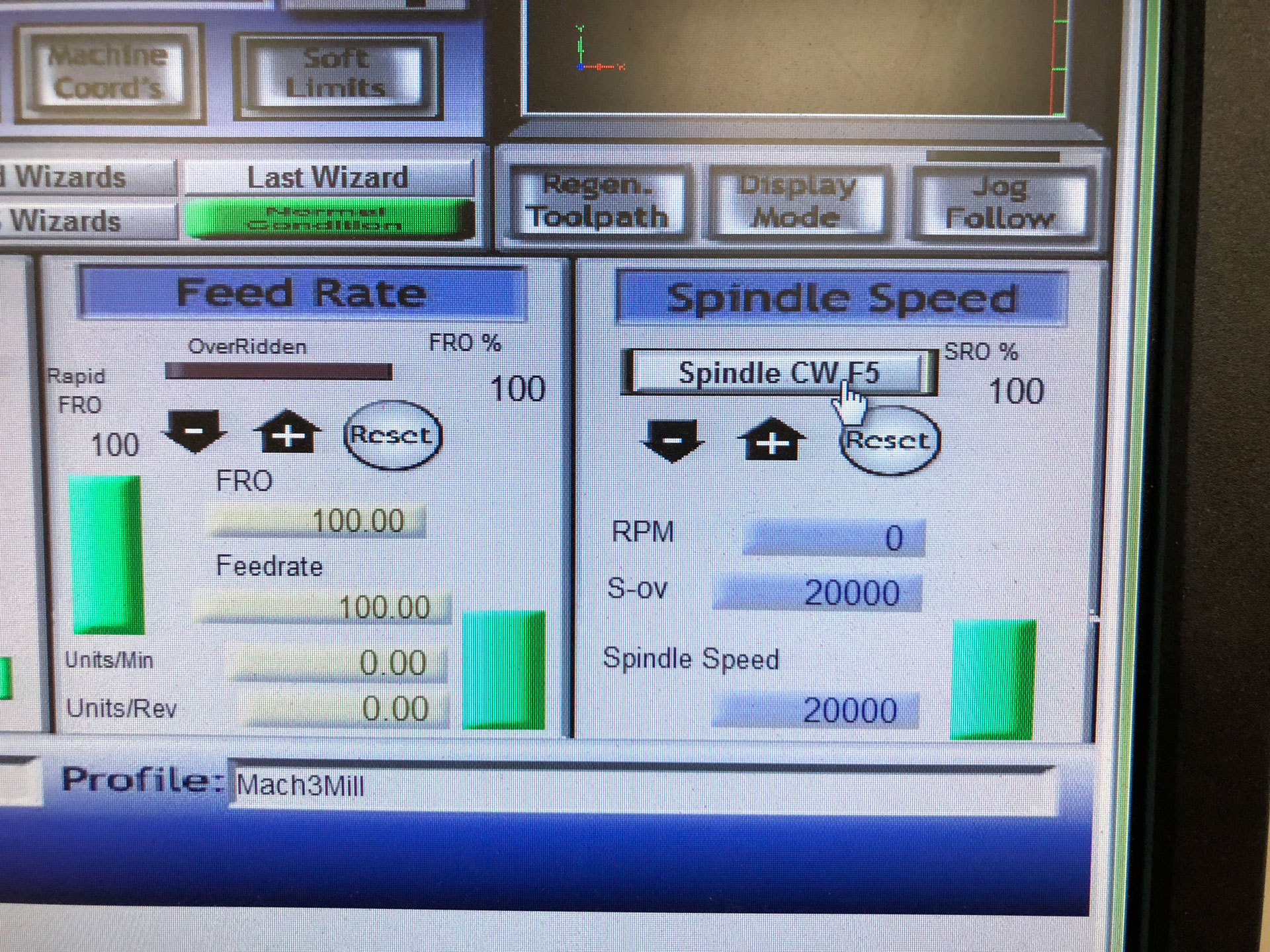
Update Feed & Speed >> Spindle Speed of 20000 rpm, Ramp Spindle Speed of 20000 rpm, Cutting Feedrate of 100 in/min, Lead-In Feedrate of 100 in/min, Lead-Out Feedrate of 100 in/min, Plunge Feedrate of 100 in/min, Feed per Revolution of 0.005 in
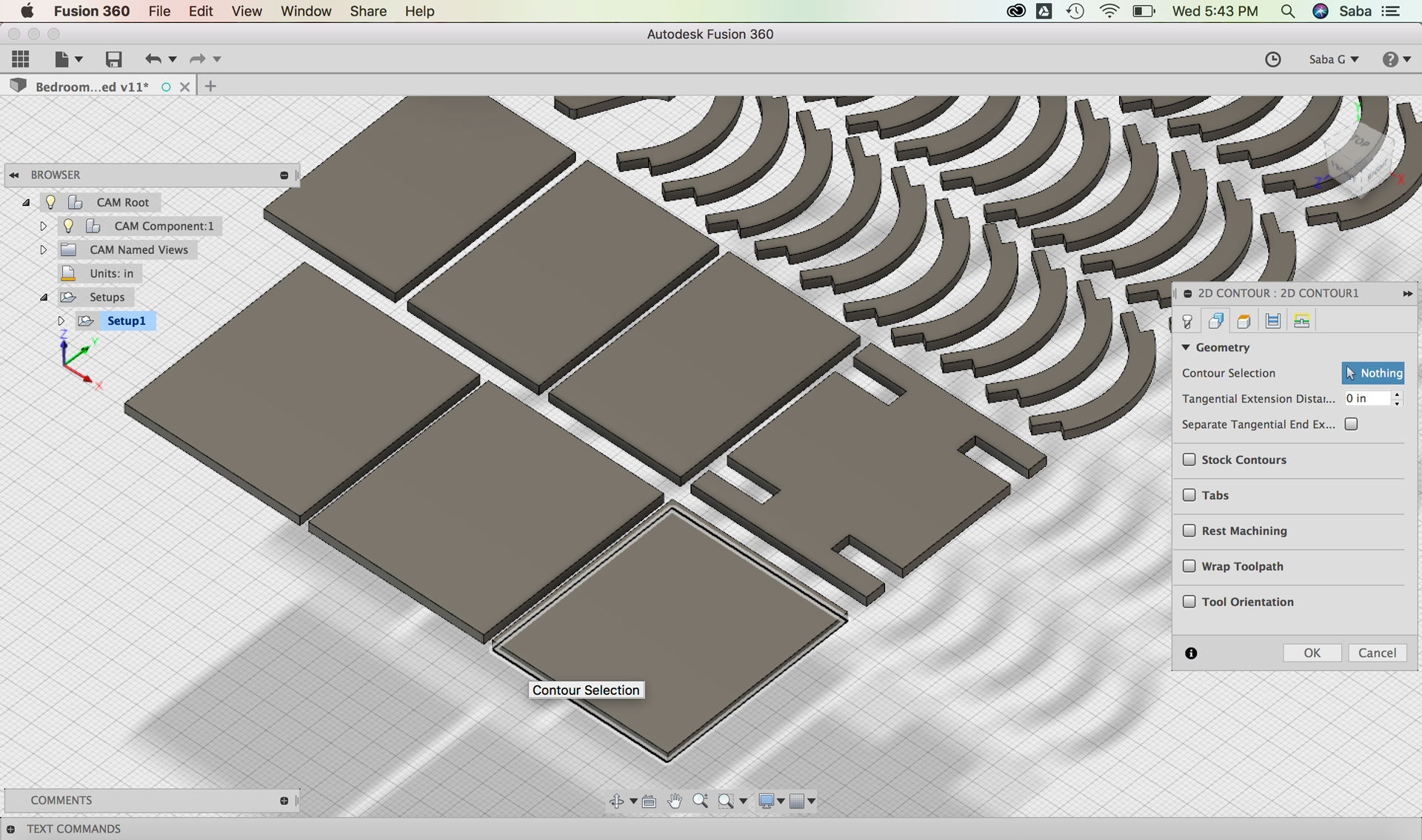
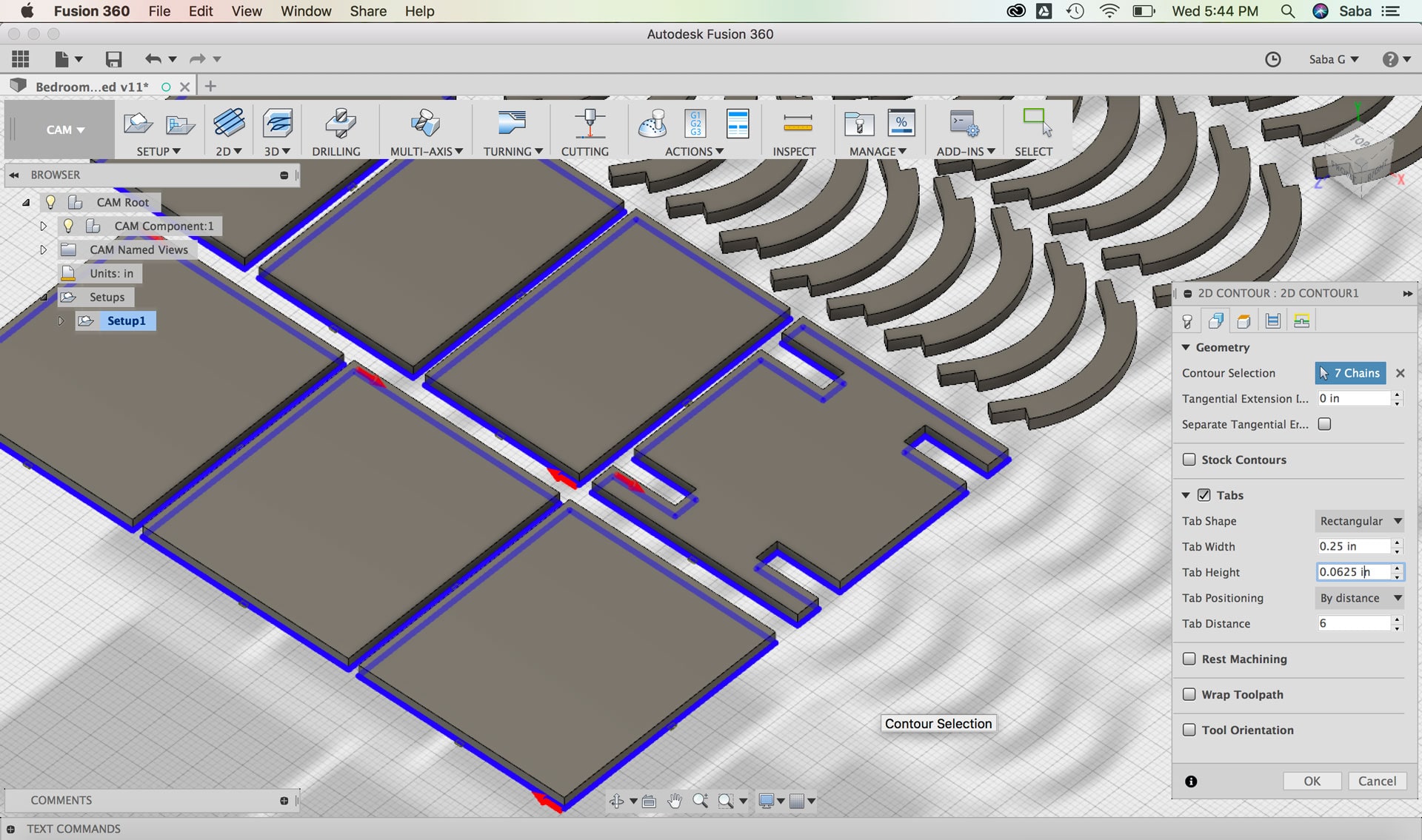
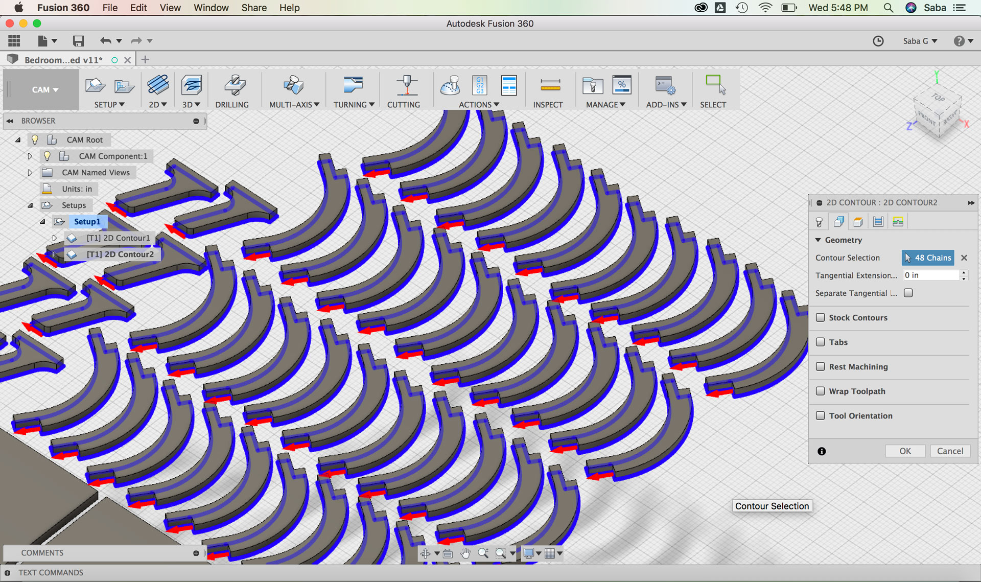
Under Geometry tab:
Contour Selection: select bottom facing contours
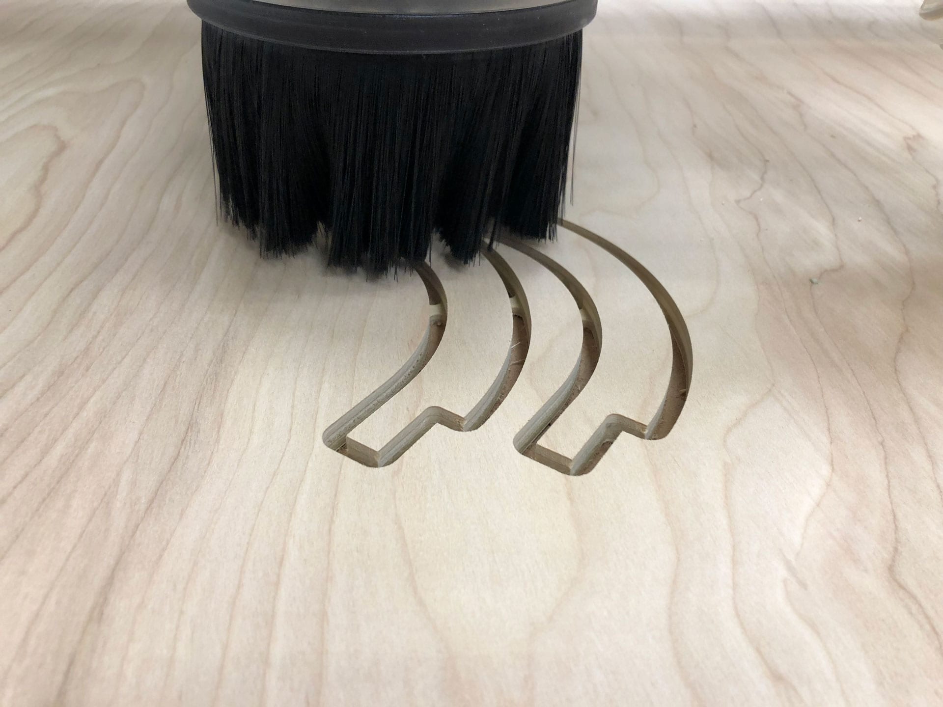
Tabs: I set the Tab Width to 0.25” and Tab Height to 0.2” by distance and then selected the Tab Distance to 5 after some experimentation (You don’t want too many or too few)
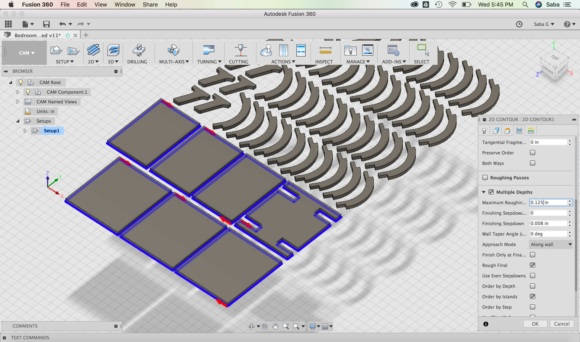
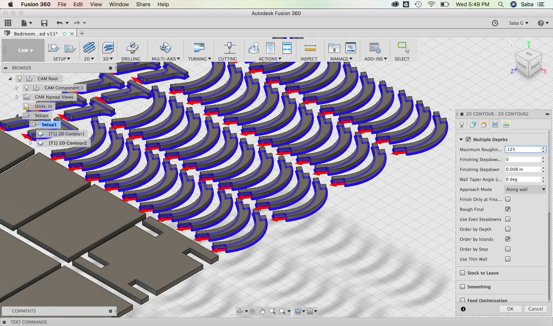
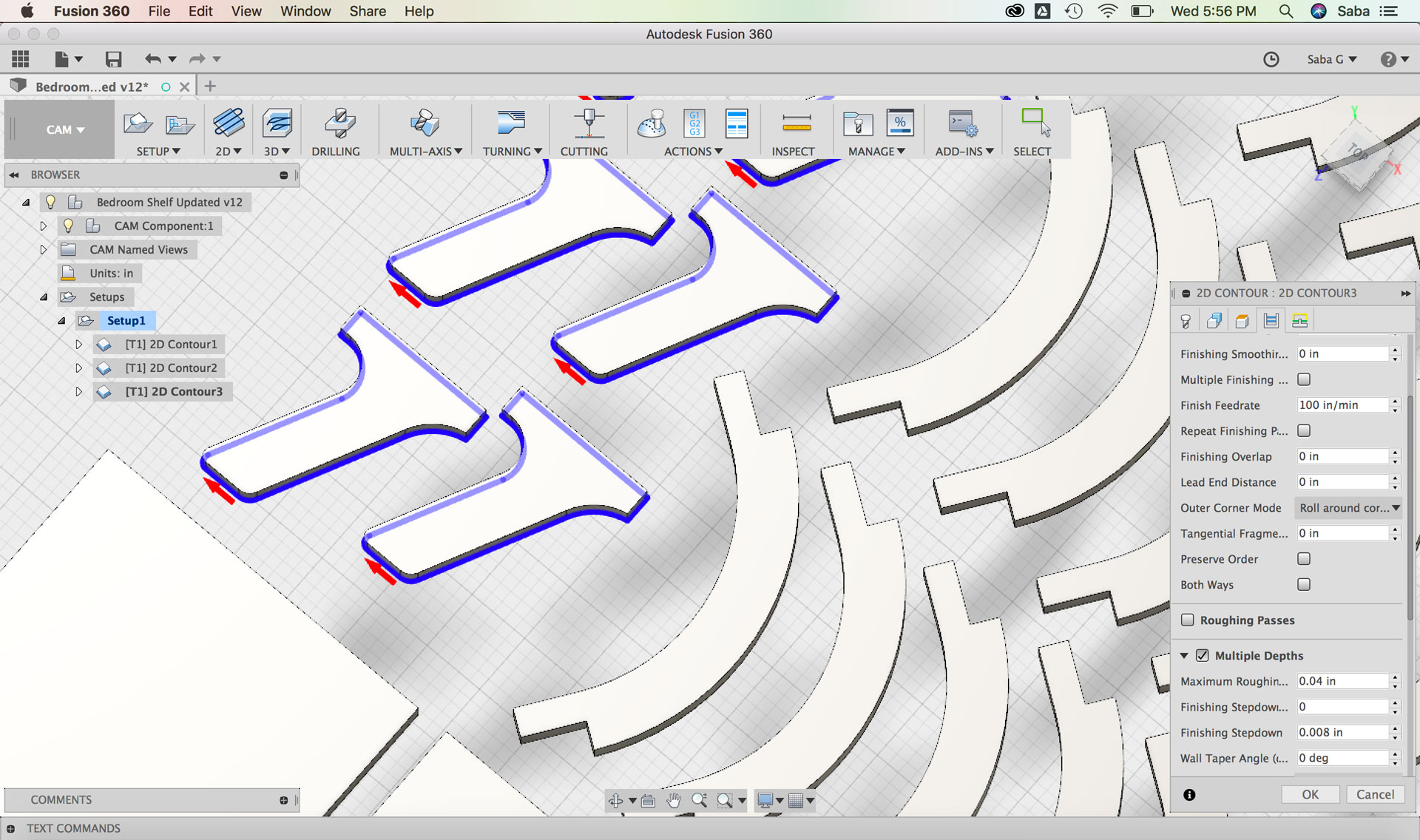
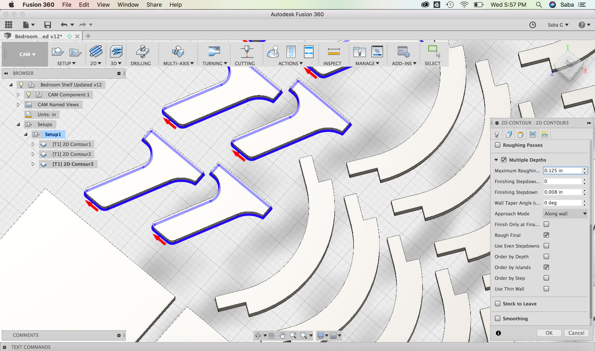
Under Passes tab:
Under Multiple Depths, set Maximum Roughing to 0.125”
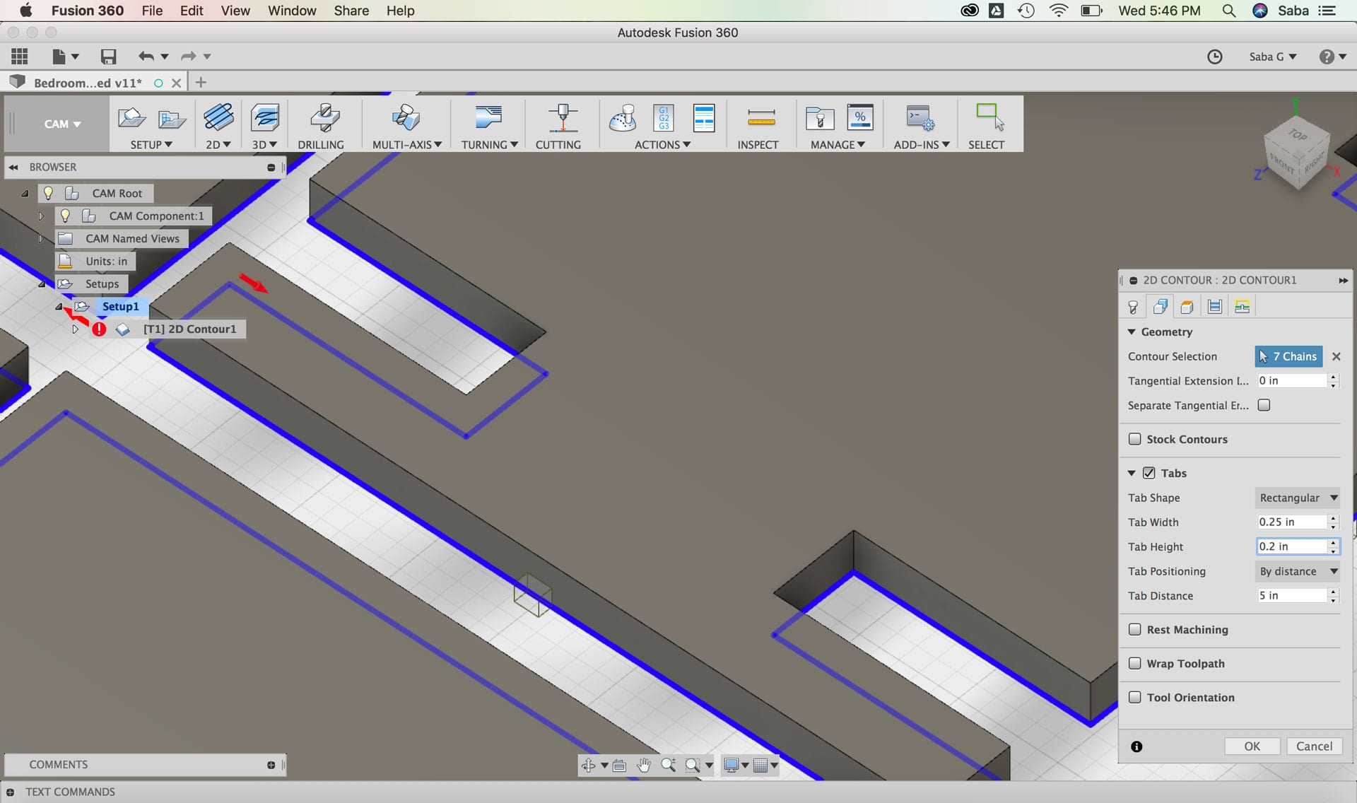
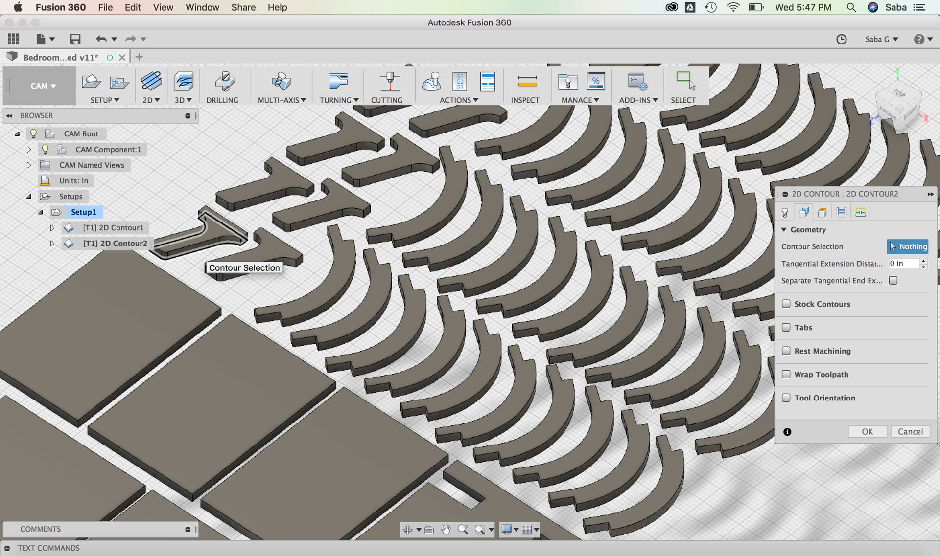
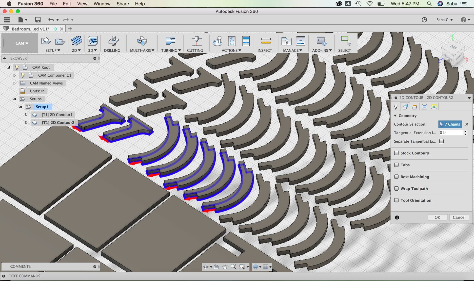
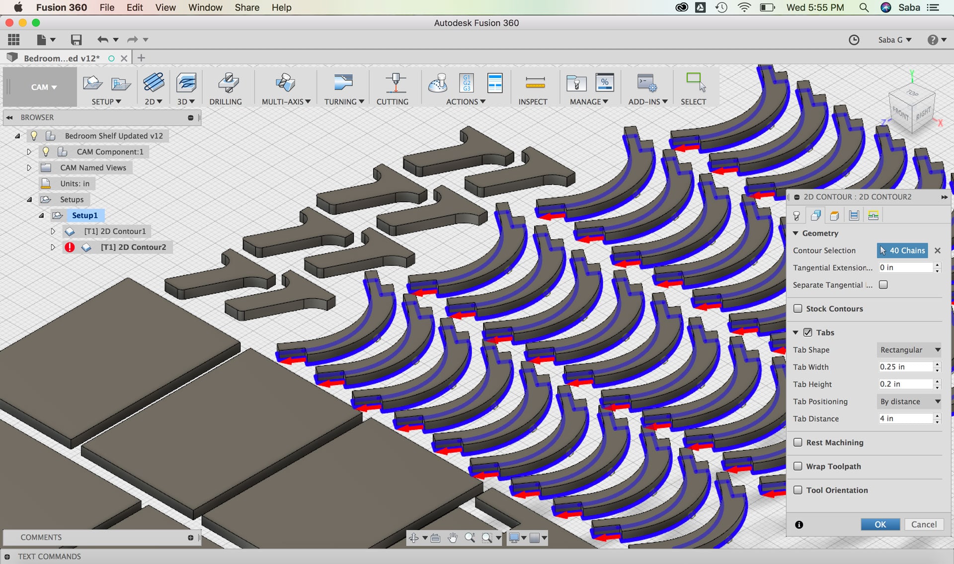
For my second toolpath, I duplicated the 2D Contour feature that I had just created with the settings and did the following steps for the smaller corner pieces given that they would have slightly different tabs:
Under Geometry tab:
Contour Selection: select bottom facing contours
Tabs: I set the Tab Width to 0.25” and Tab Height to 0.2” by distance and then selected the Tab Distance to 4 after some experimentation (You don’t want too many or too few)
Under Passes tab:
Under Multiple Depths, set Maximum Roughing to 0.125”
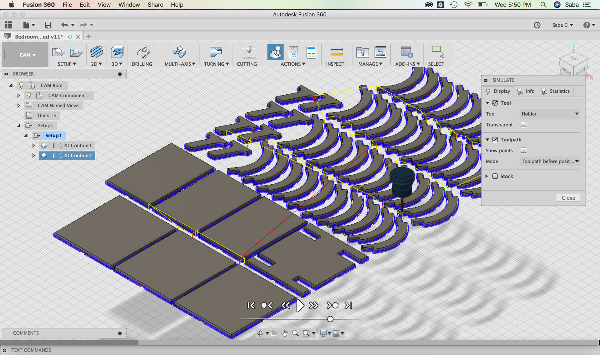
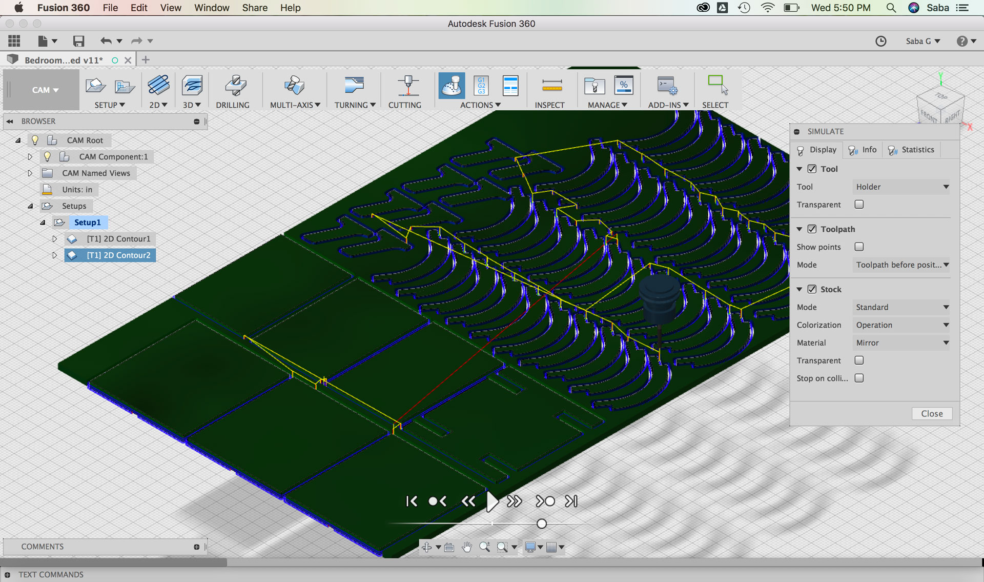
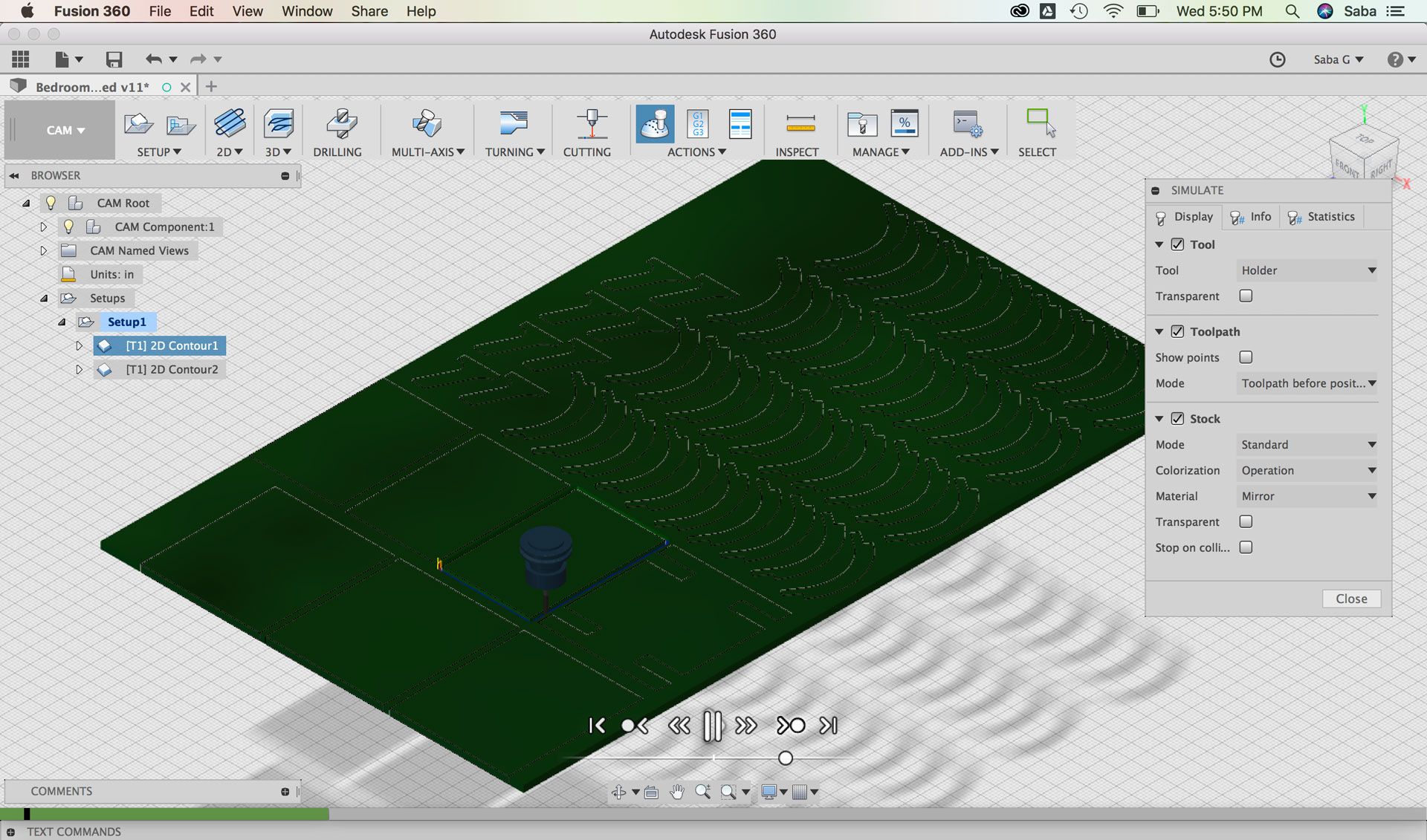
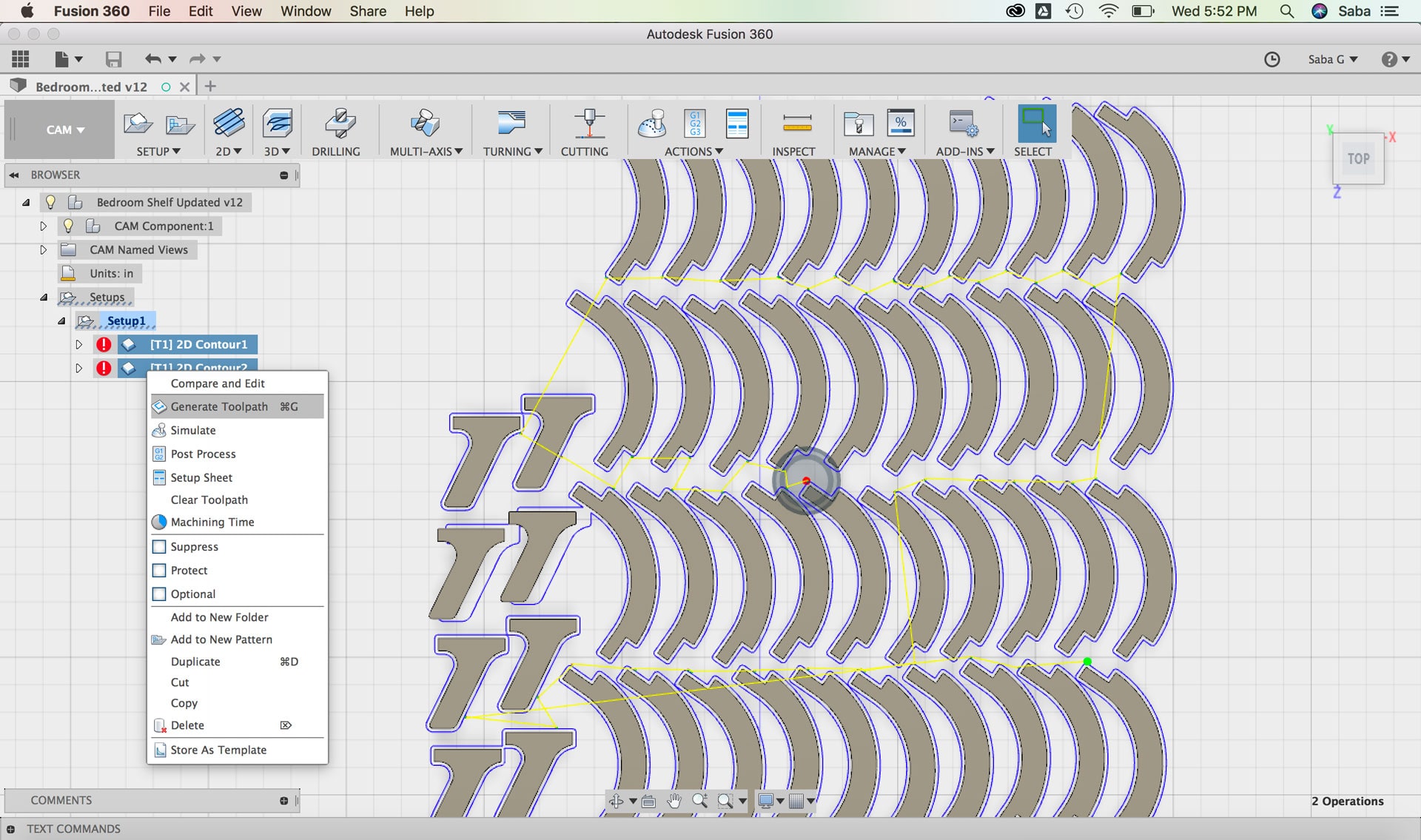
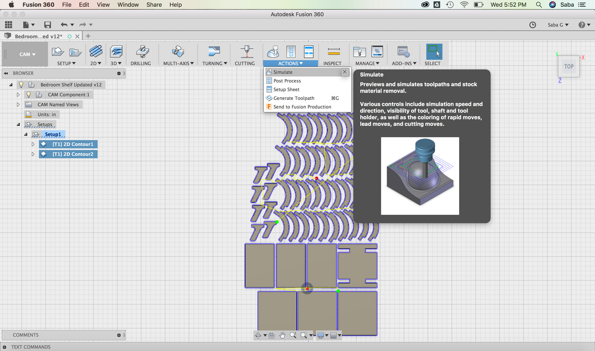
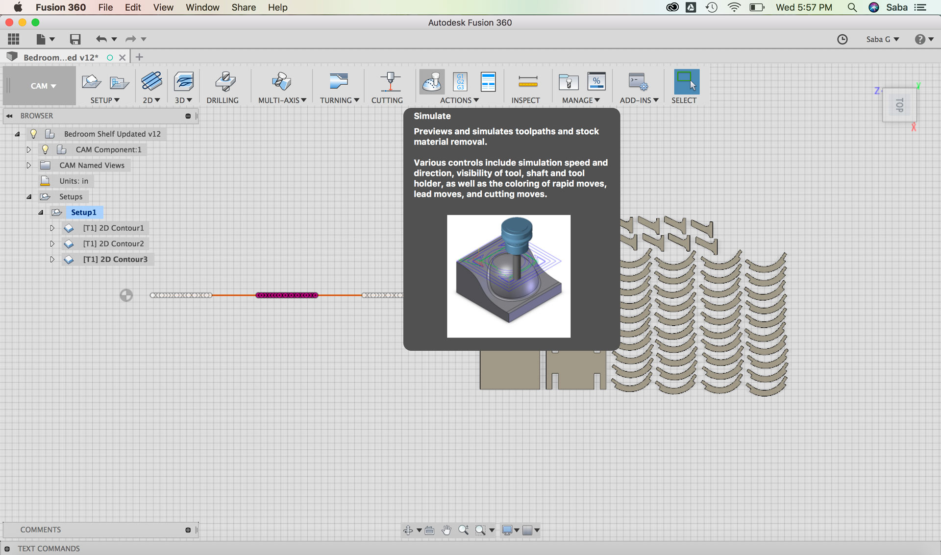
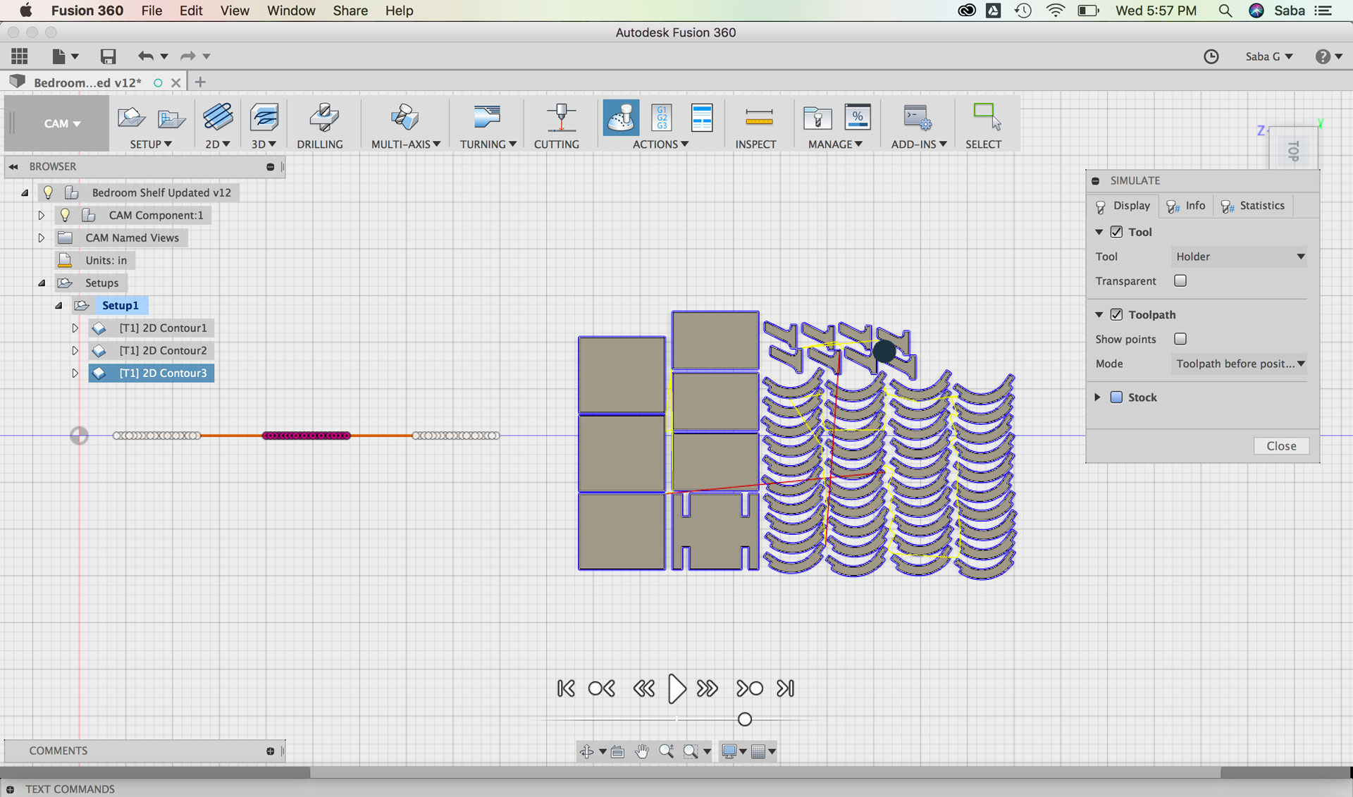
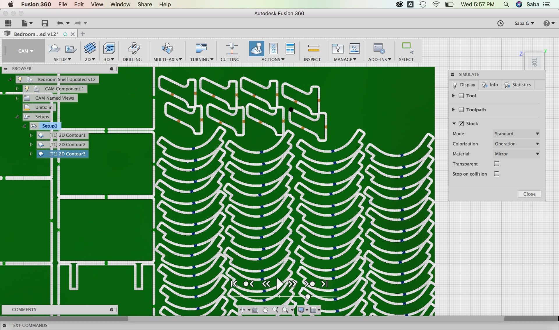
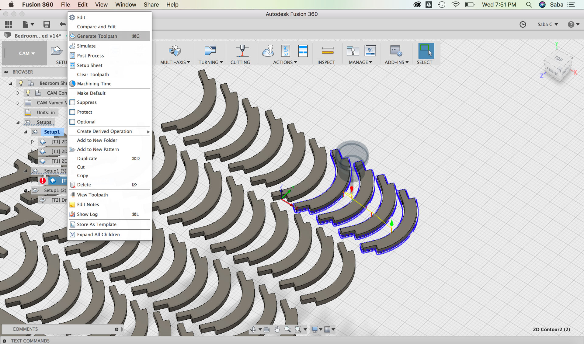
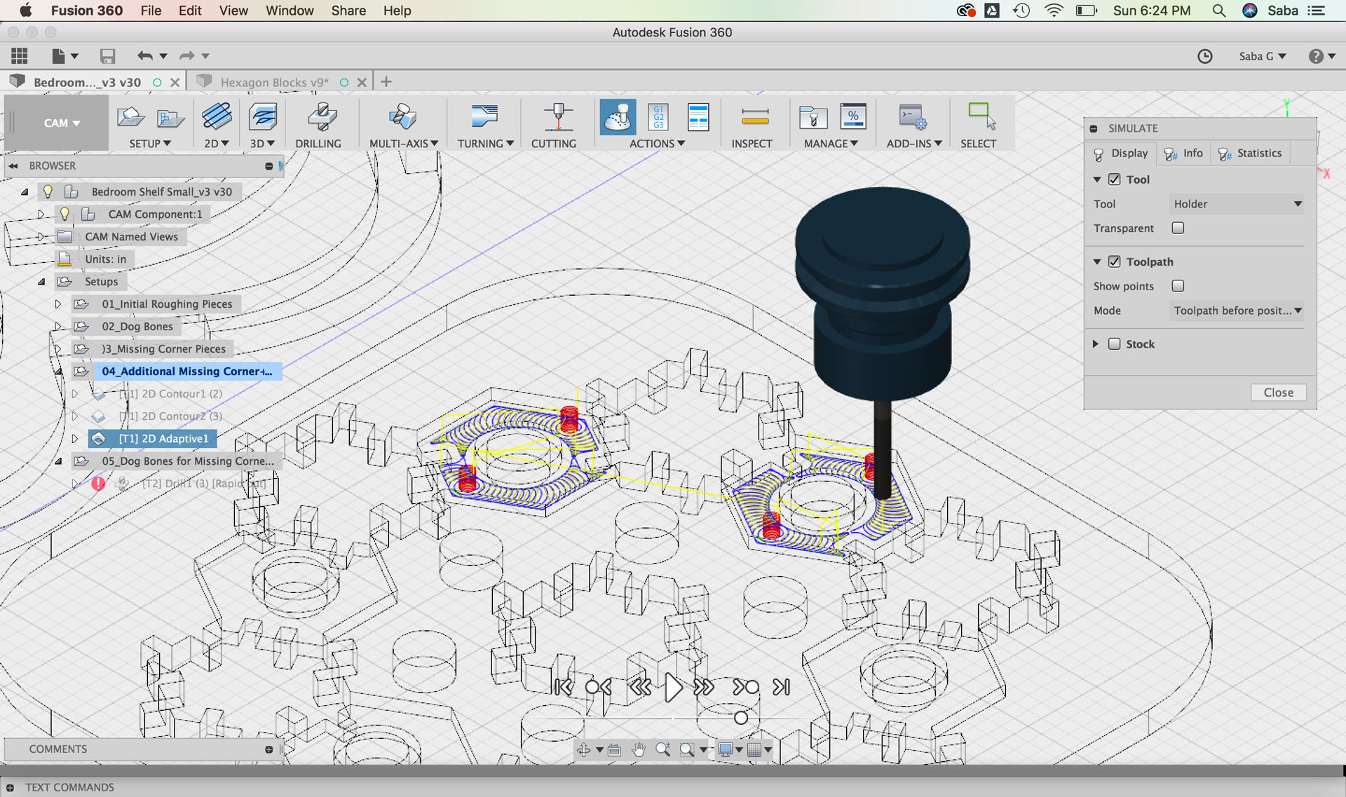
I right-clicked on both the 2D Contour paths and selected “Generate Toolpath.” I then selected the Simulate command and under the “Display” tab, I made sure the Tool, Toolpath, and Stock boxes were checked on to preview and simulate toolpaths and stock removal.
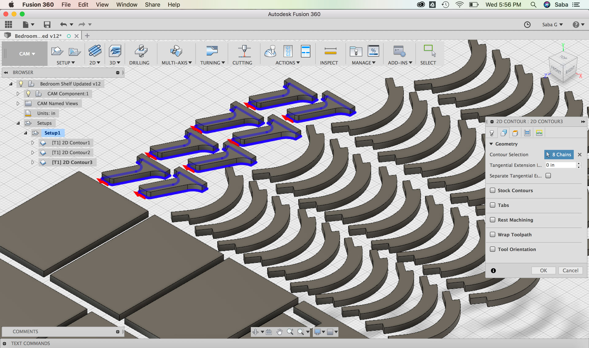
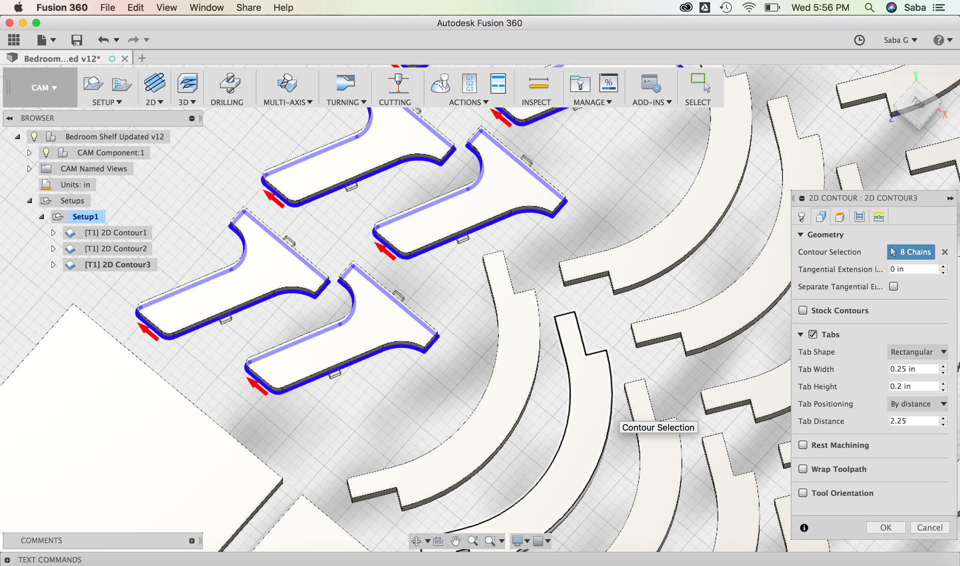
I realized that I had made one error: the legs included in the previous 2D Contour toolpath needed a different toolpath. I therefore needed to remove them from the previous toolpath and create a separate one. I duplicated the prior toolpath and modified the following:
Under Geometry tab:
Contour Selection: select bottom facing contours of Leg pieces
Tabs: I set the Tab Width to 0.25” and Tab Height to 0.2” by distance and then selected the Tab Distance to 2.25 after some experimentation
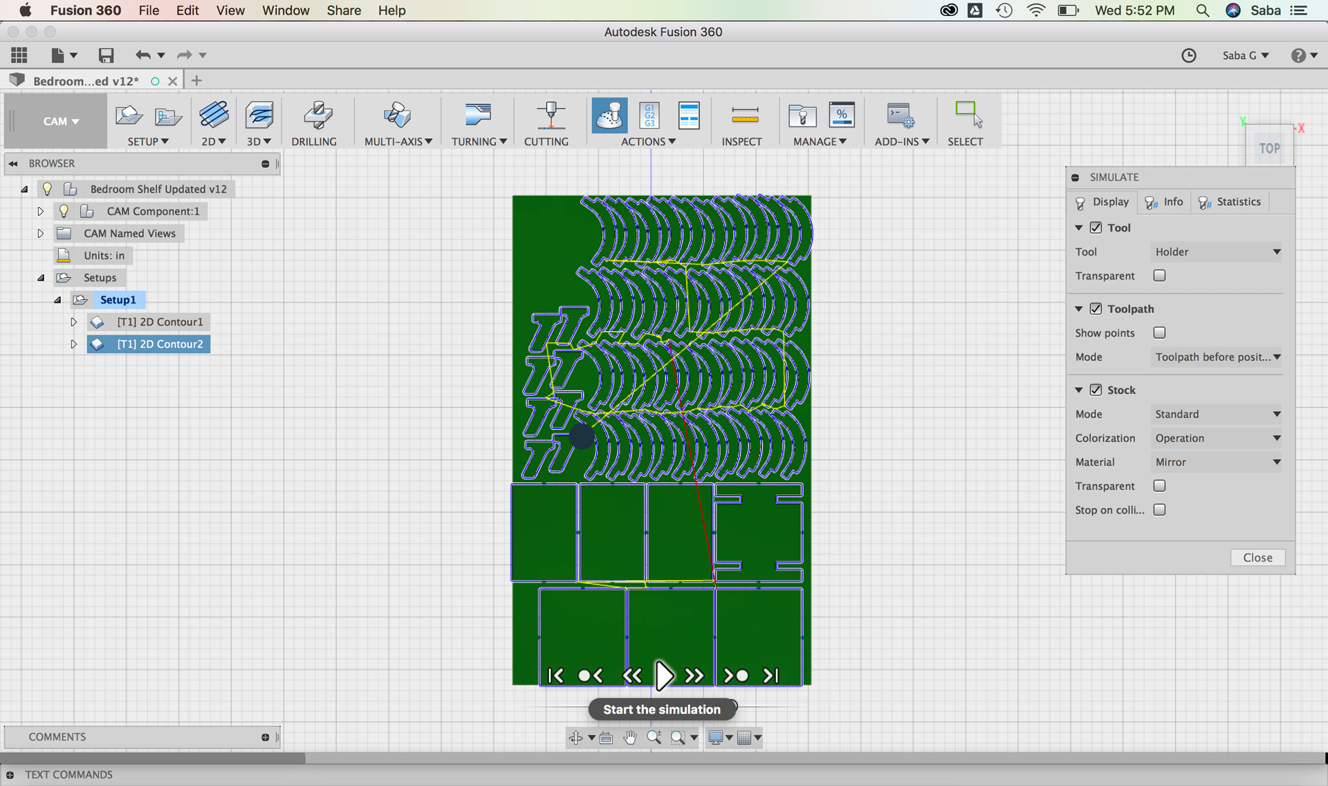
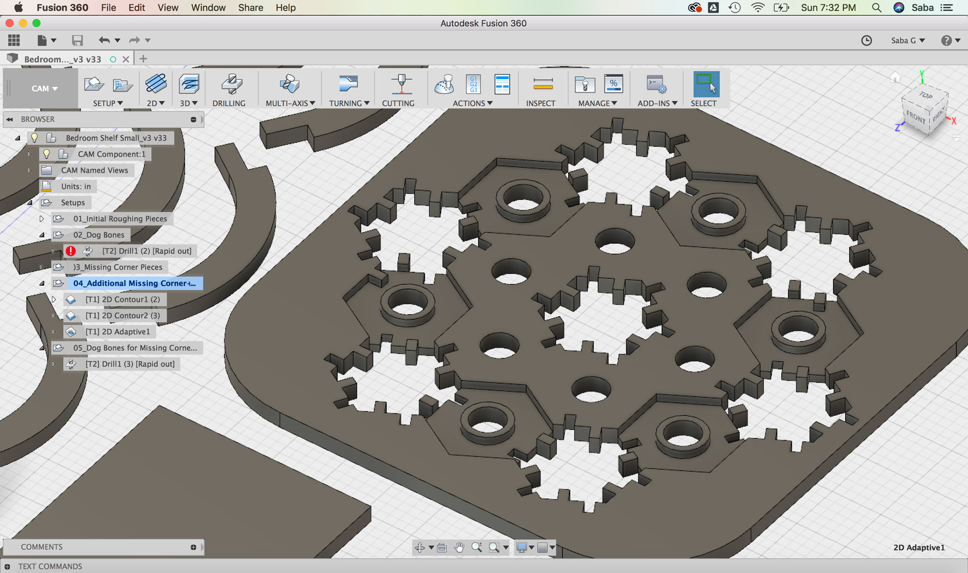
I re-generated the toolpath for the 2D Contour paths and ran another simulation. I checked if the pieces resting on the stock had enough room around each piece for cutting accurately, and it seemed to be fine.
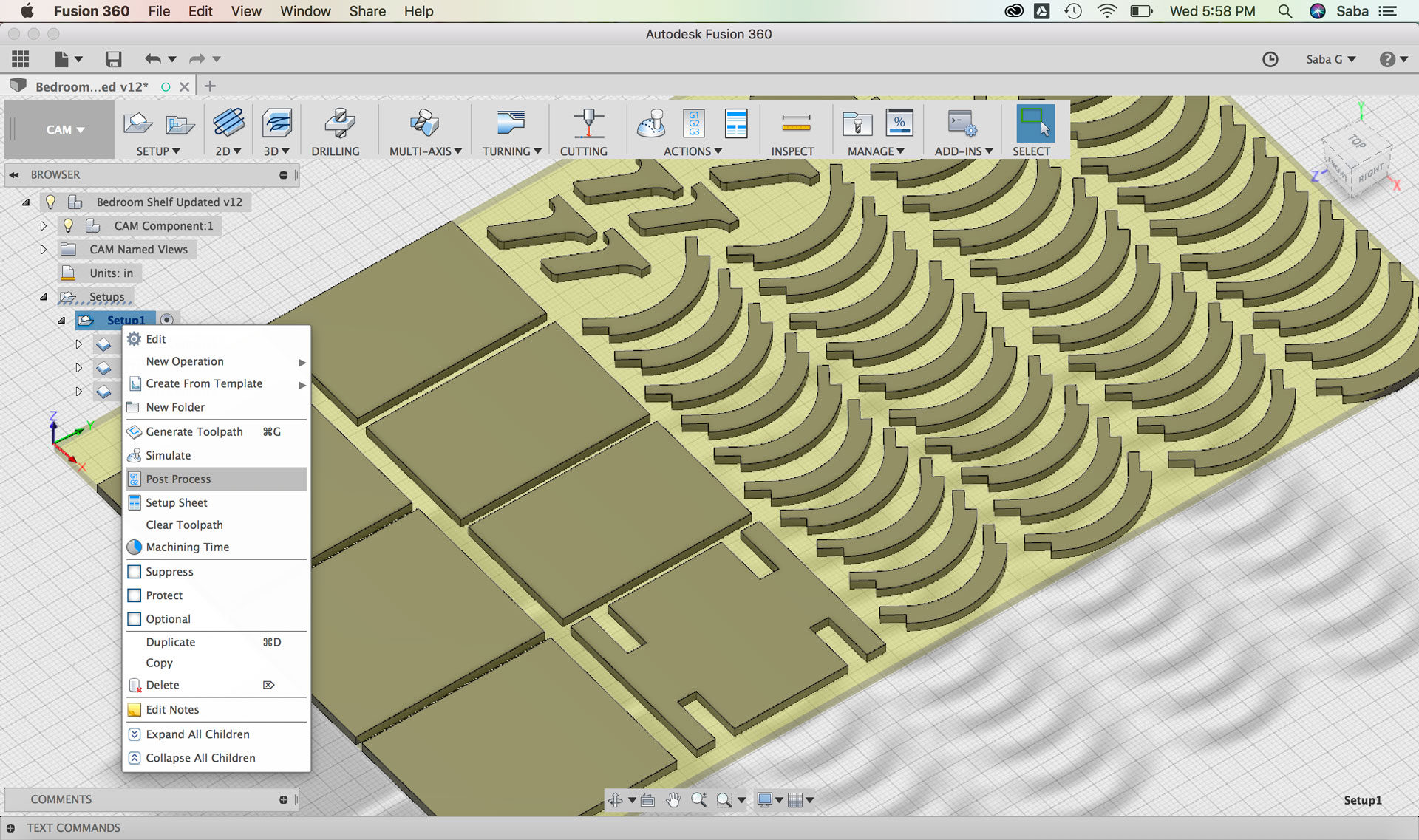
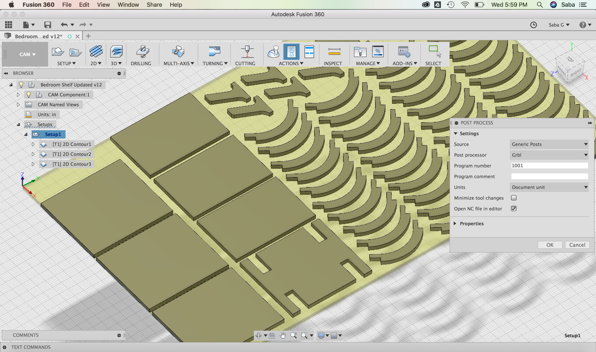
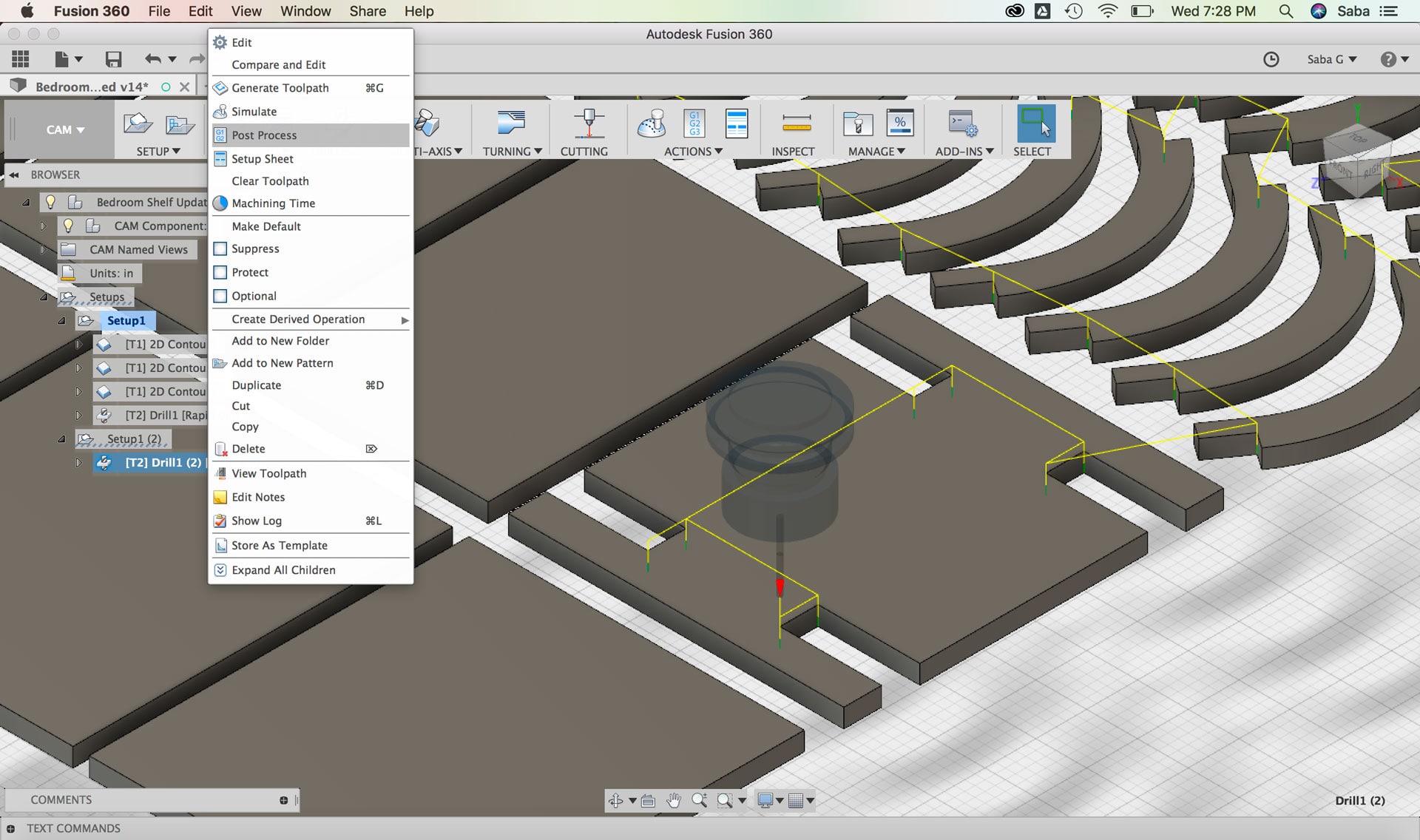
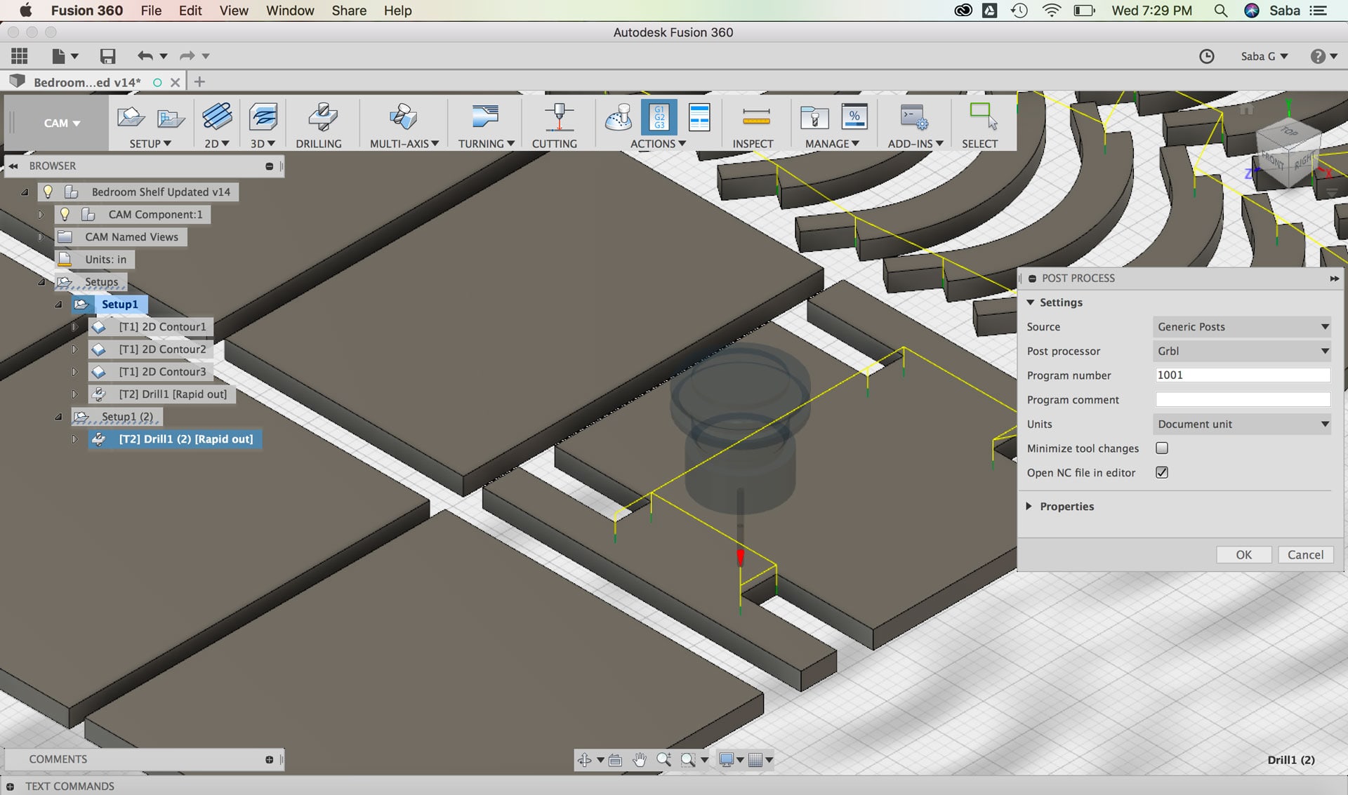
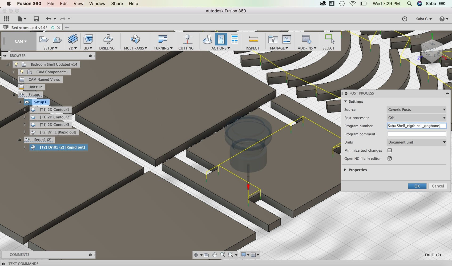
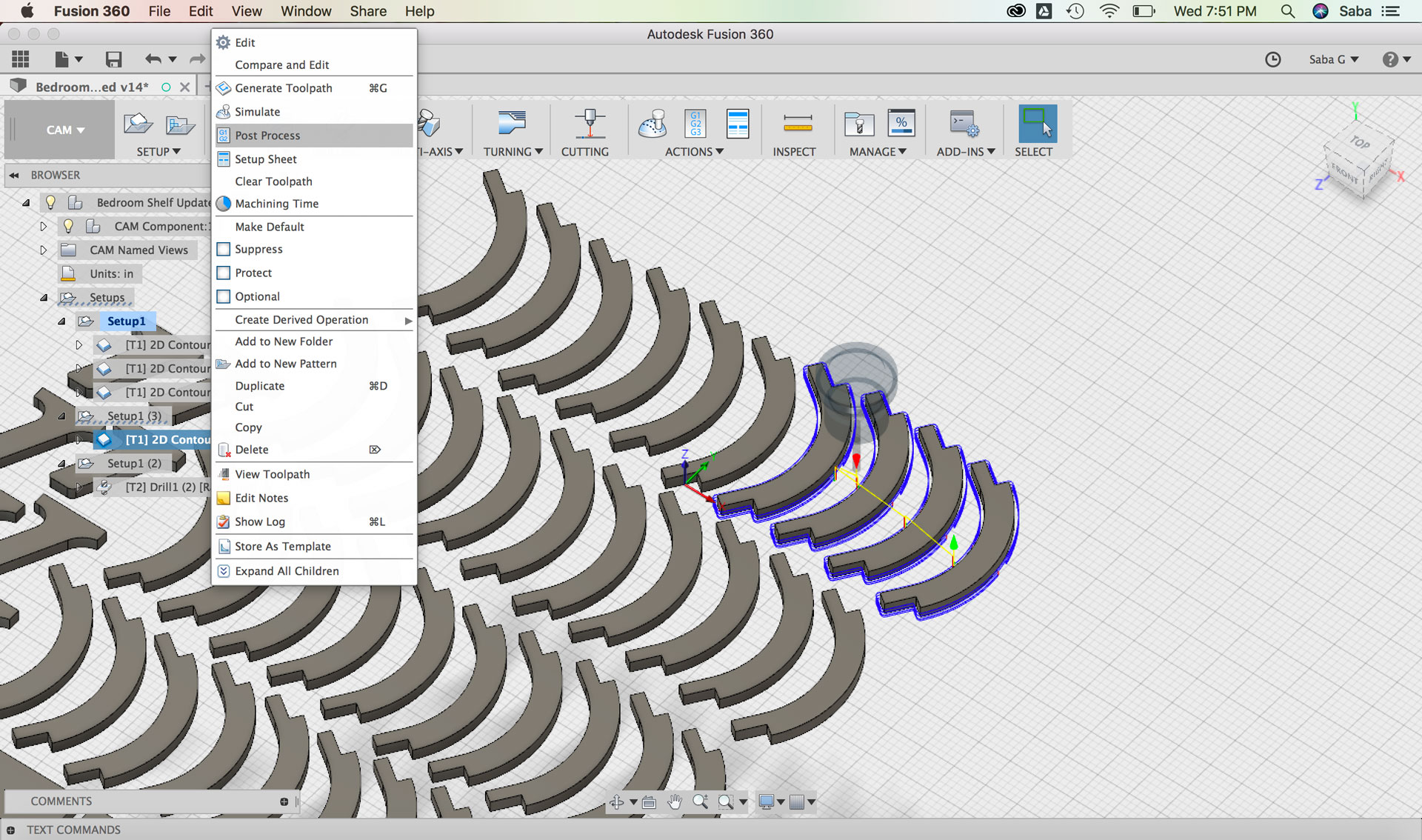
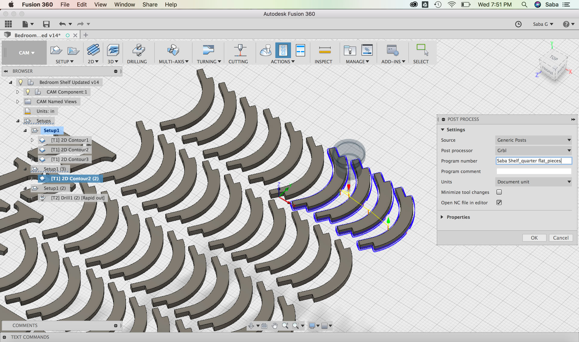
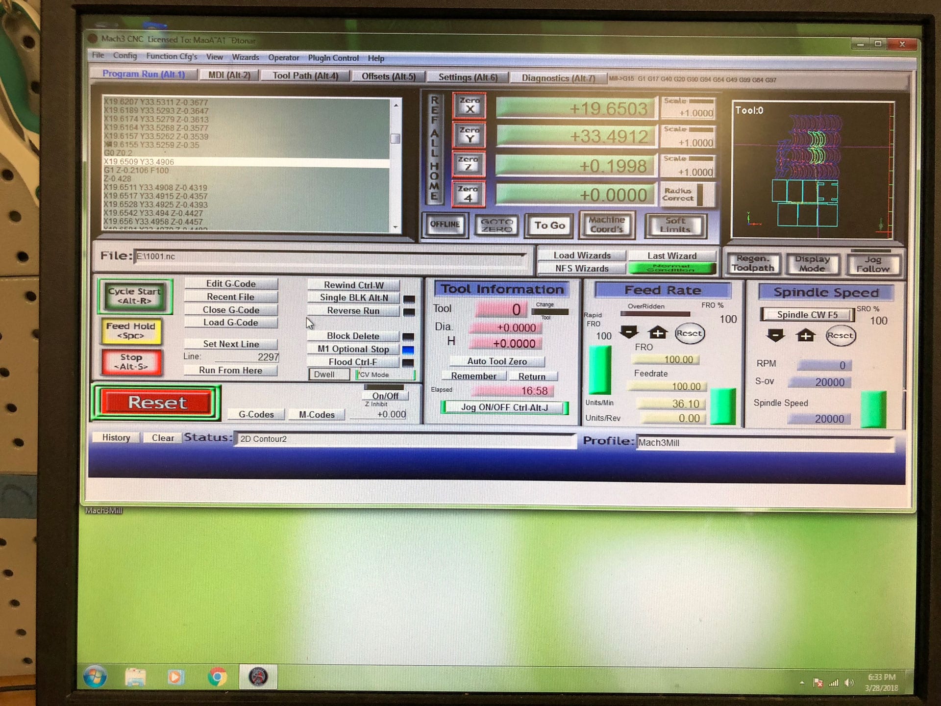
I then right-clicked on the Setup menu, selected “Post Process” and updated the following:
Under Settings tab:
Update Post Processor to Grbl
Change Program Number to 1001
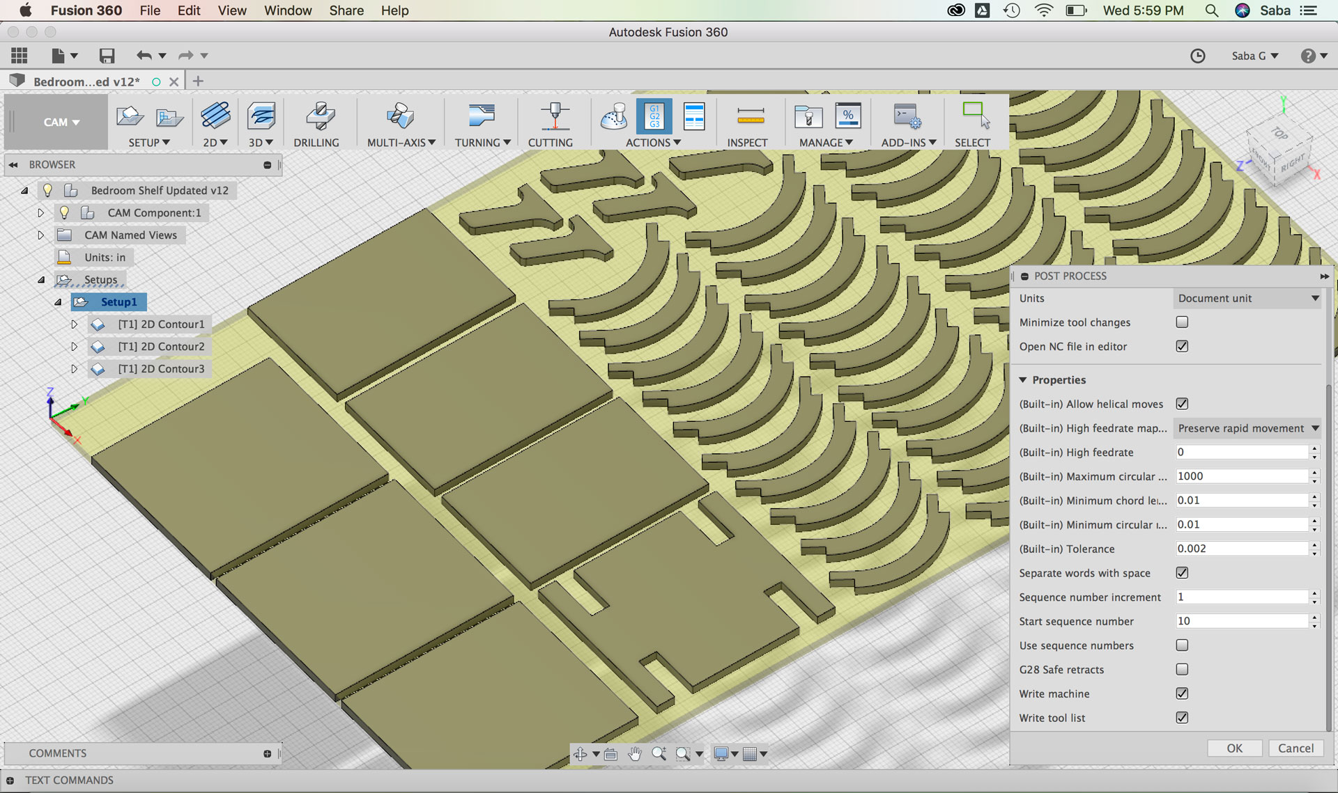
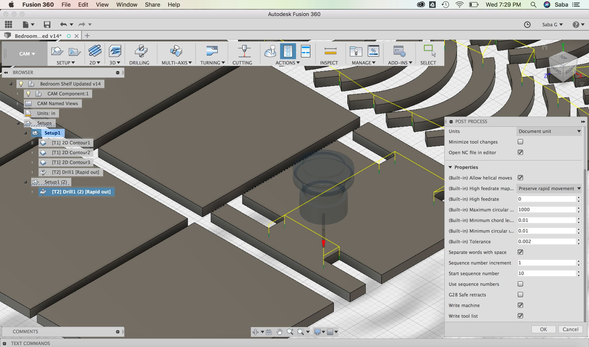
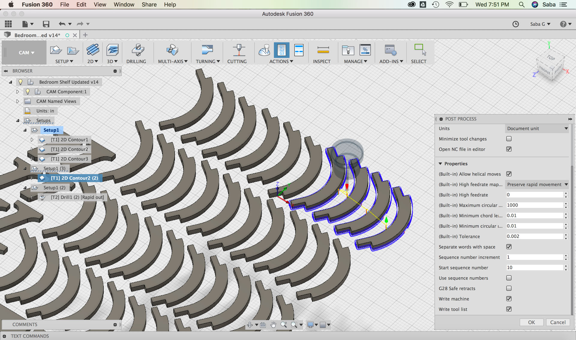
Under Properties tab:
Uncheck “G28 Safe retracts”
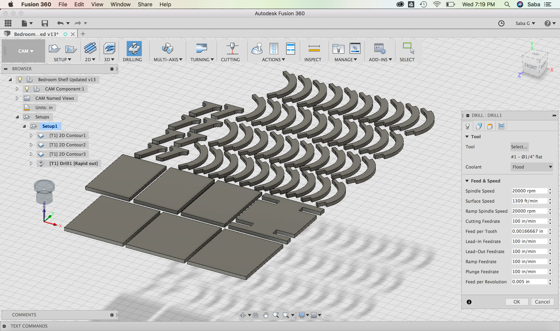
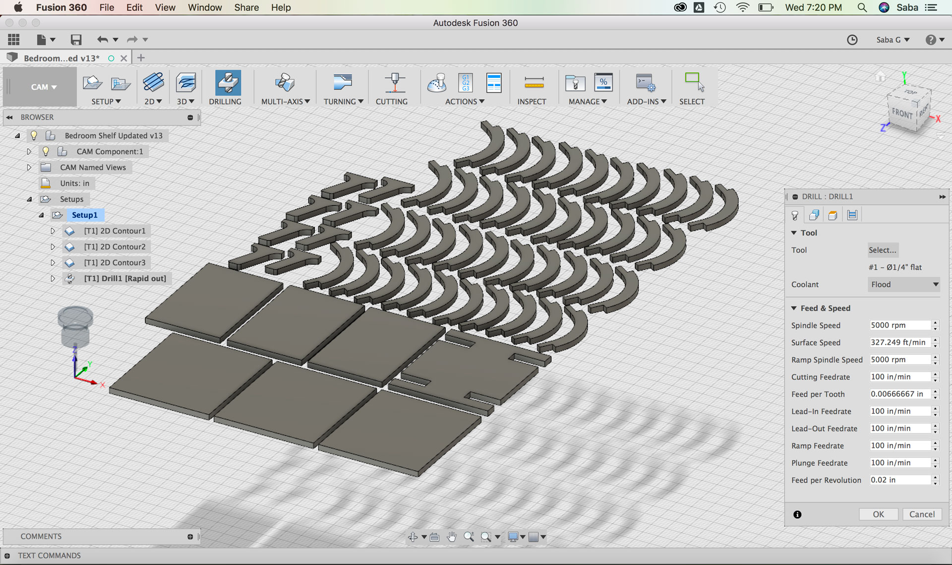
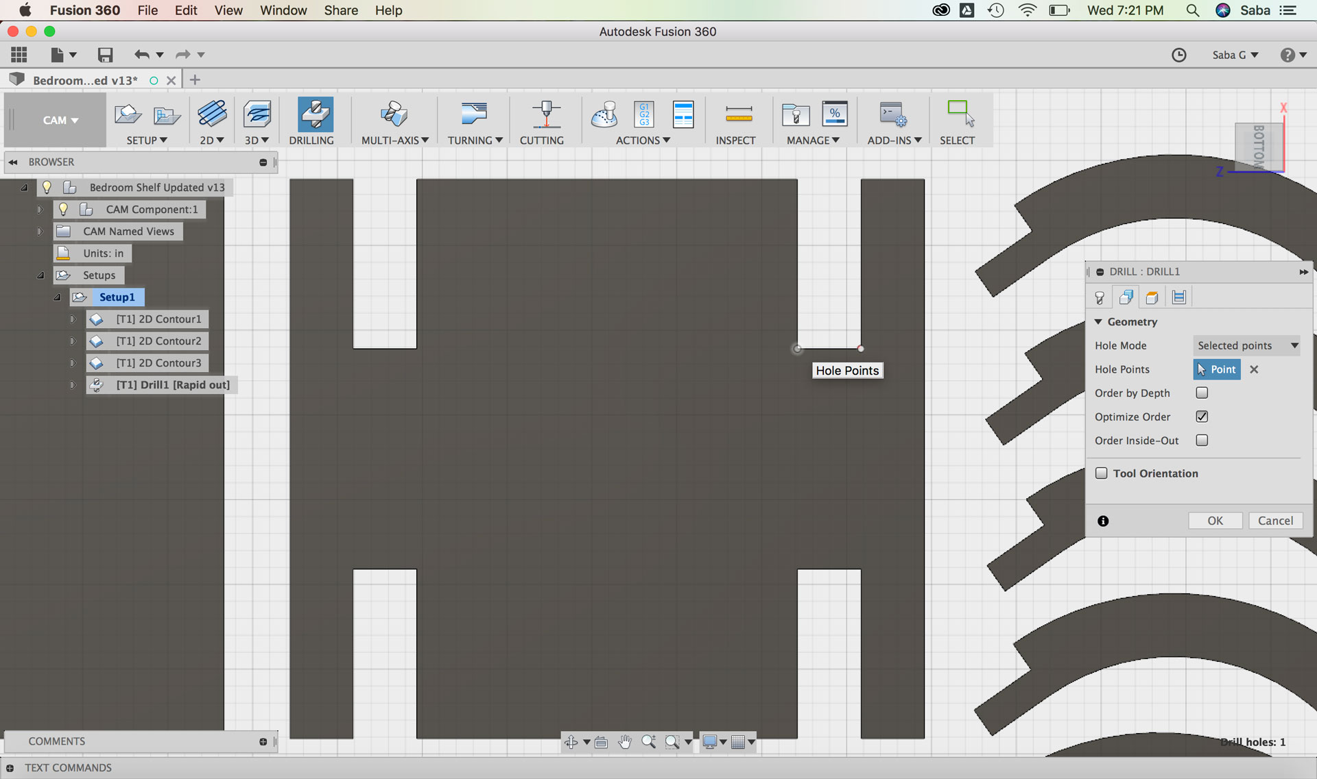
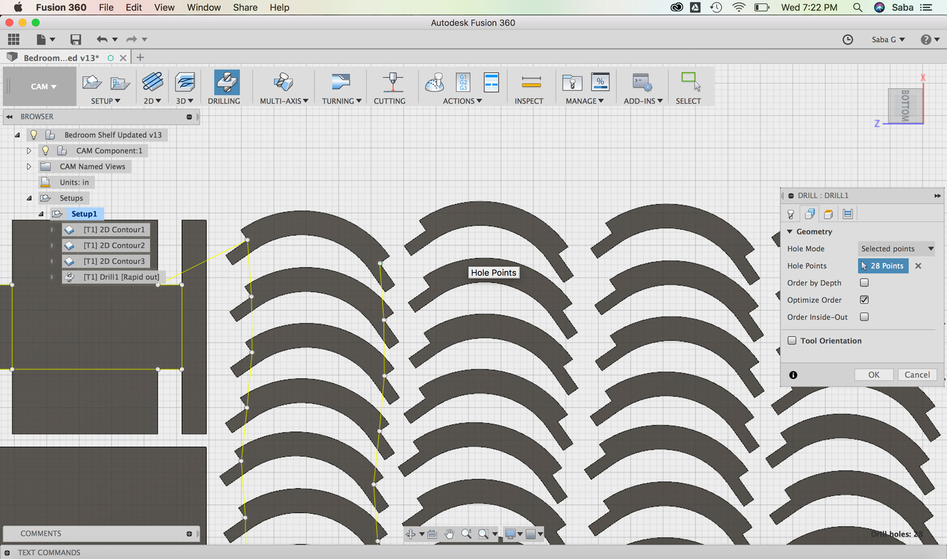
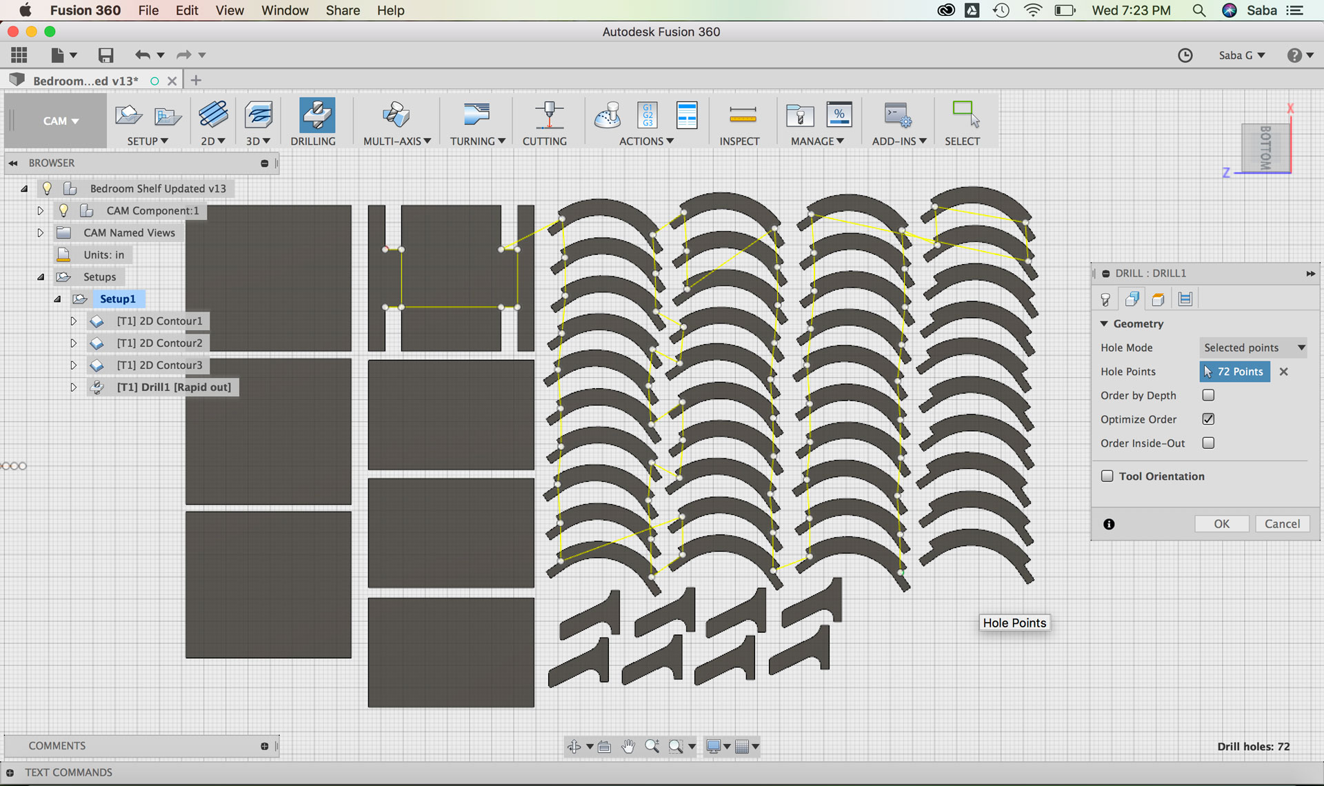
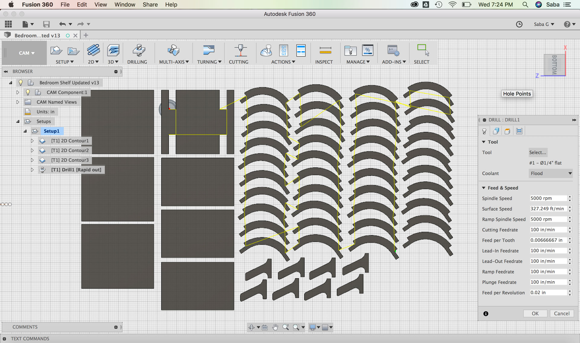
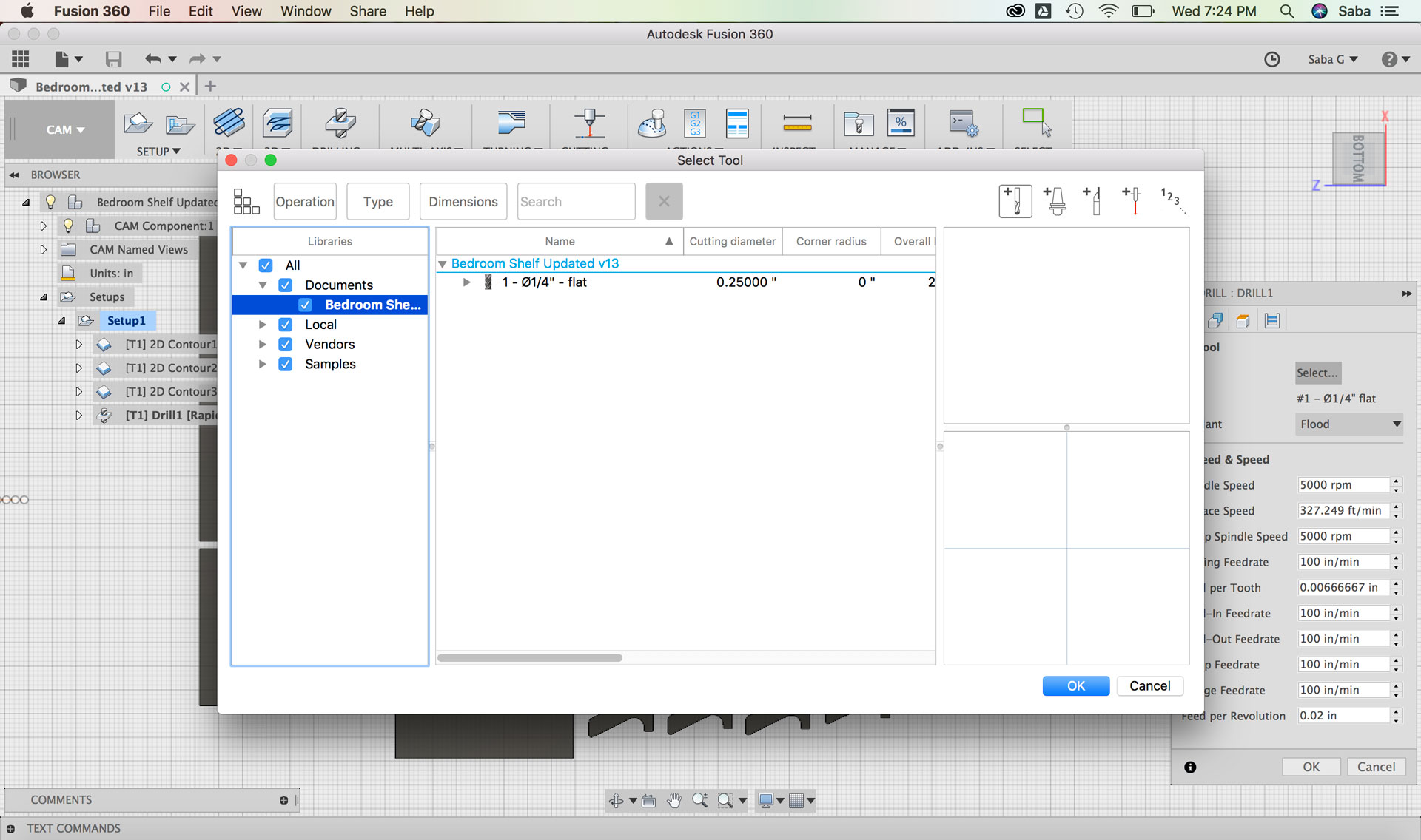
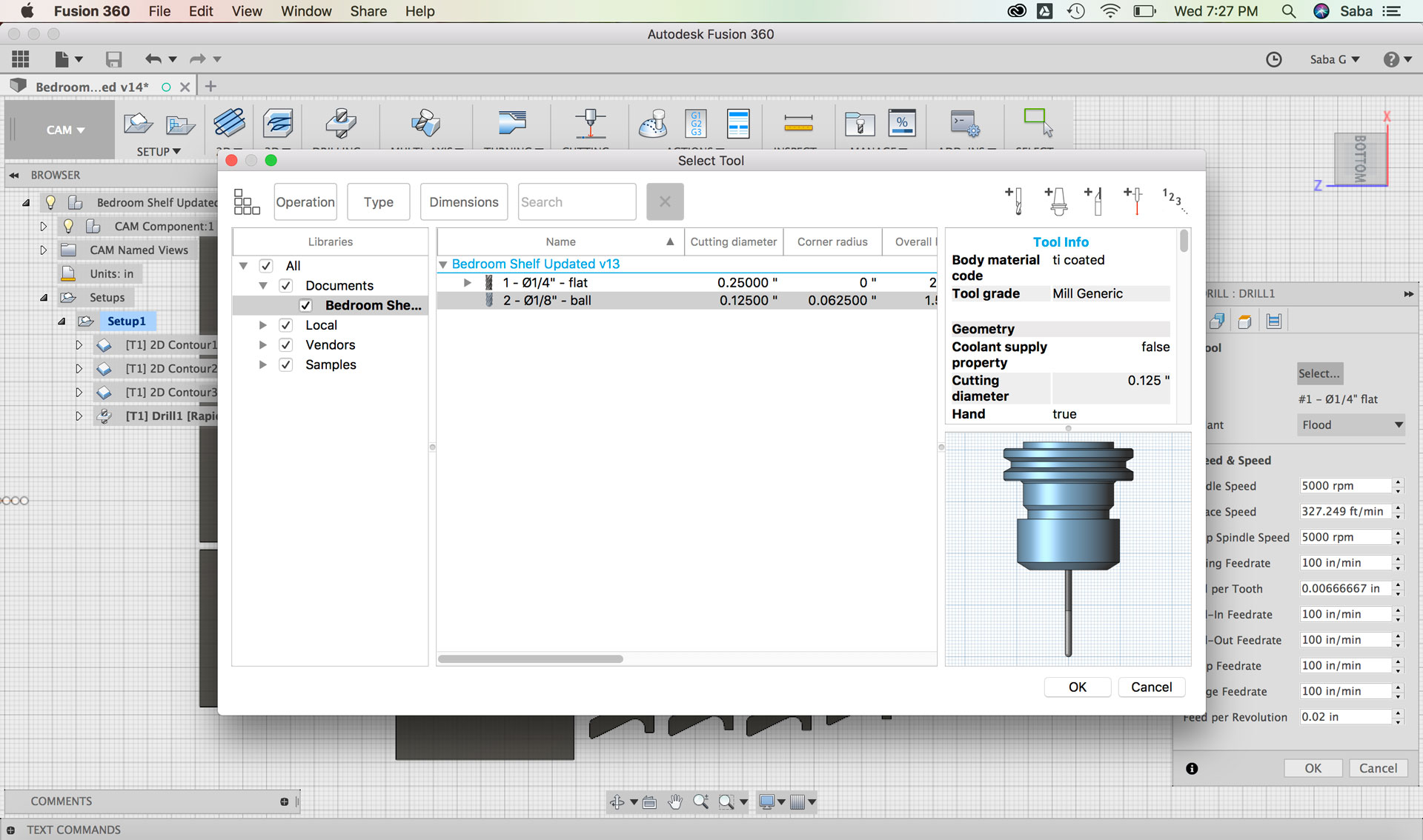
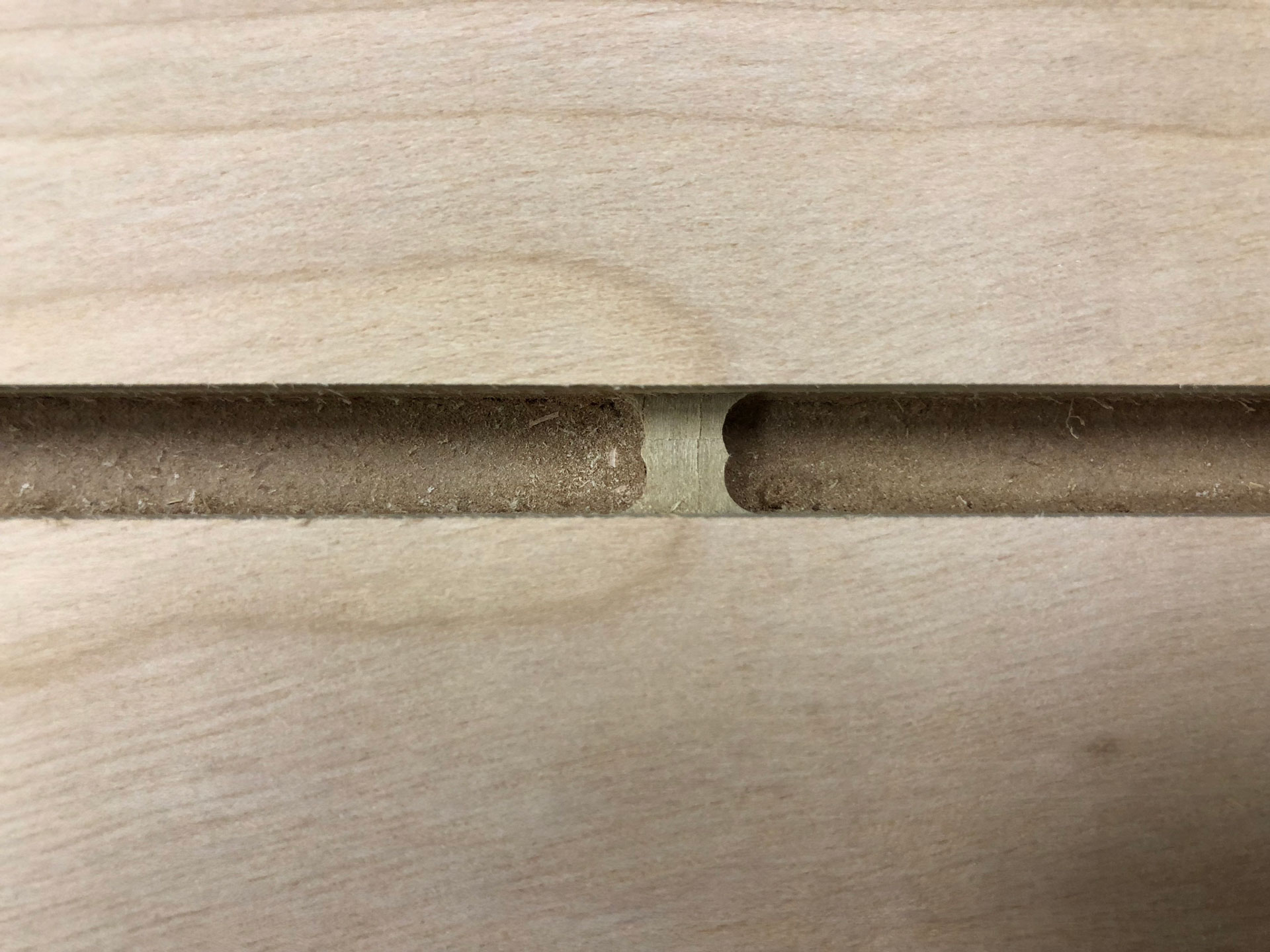
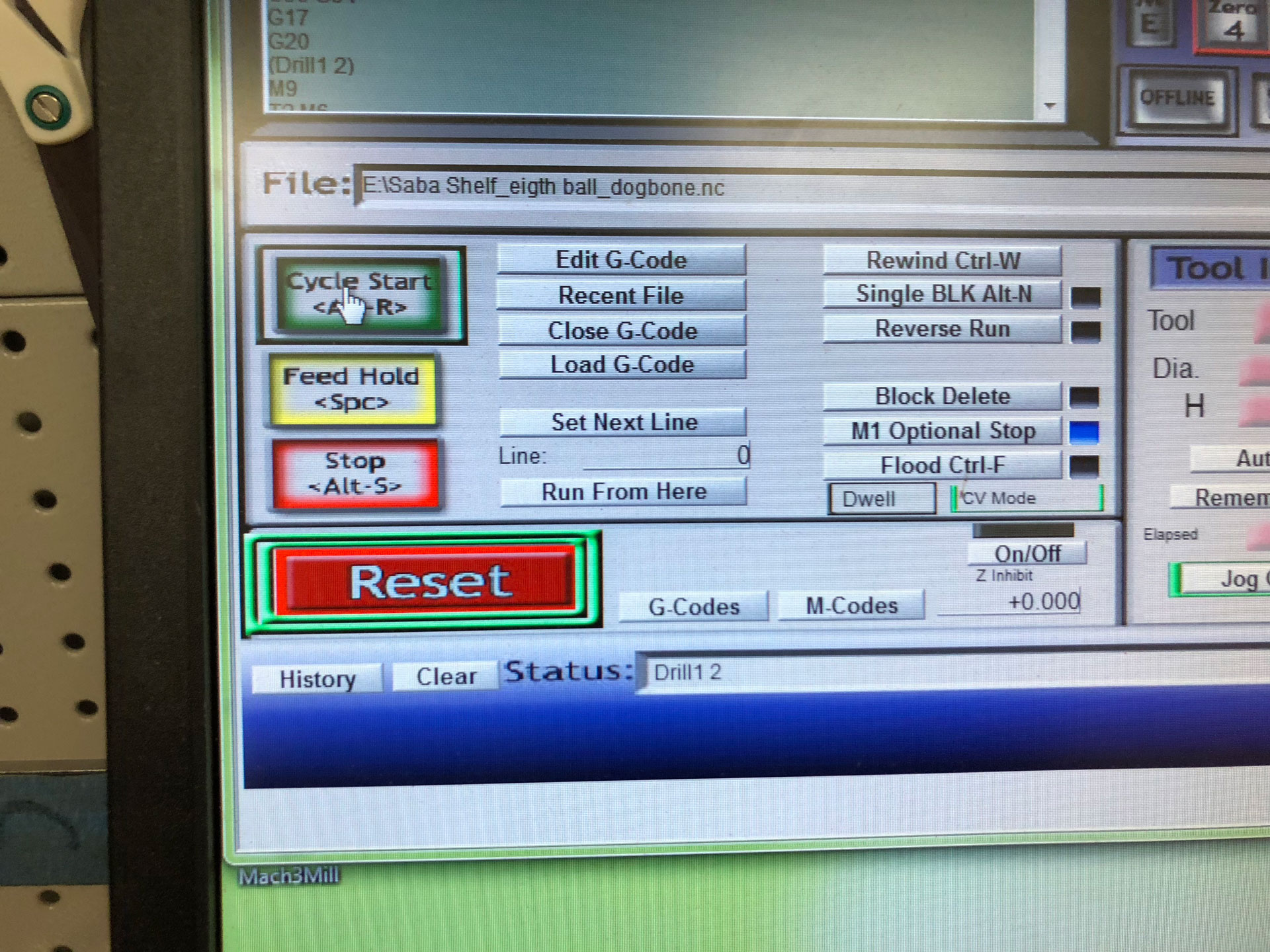
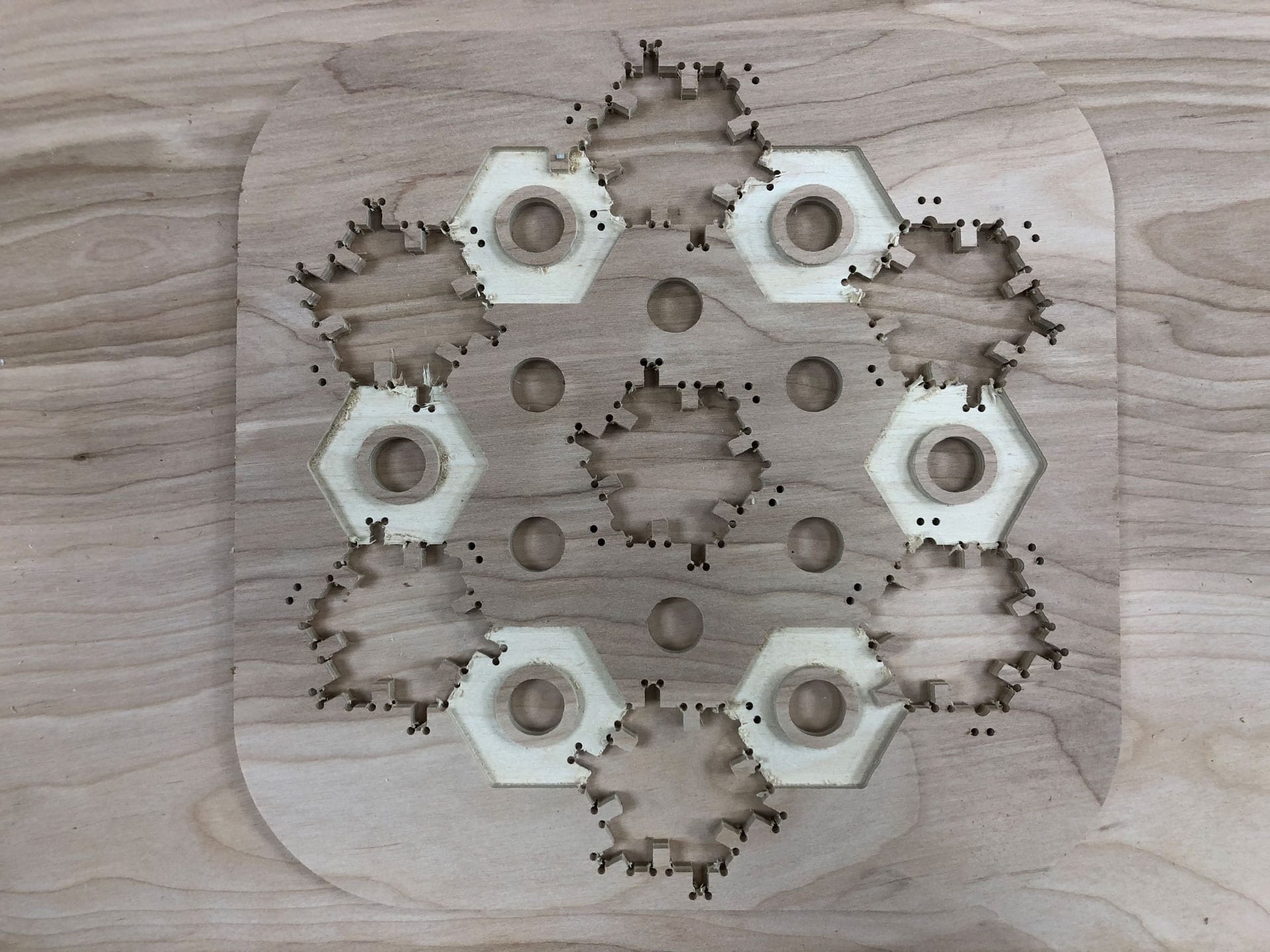
In order to ensure that my pieces would connect inside one another properly, I needed to drill dog-bone fillets at all the interior right angles. So I created one last toolpath for this procedure. I selected the Drill toolpath command and updated the following settings:
Under Tool tab:
Spindle Speed: 5000 rpm
Ramp Spindle Speed: 5000 rpm
Feed per Revolution: 0.02”
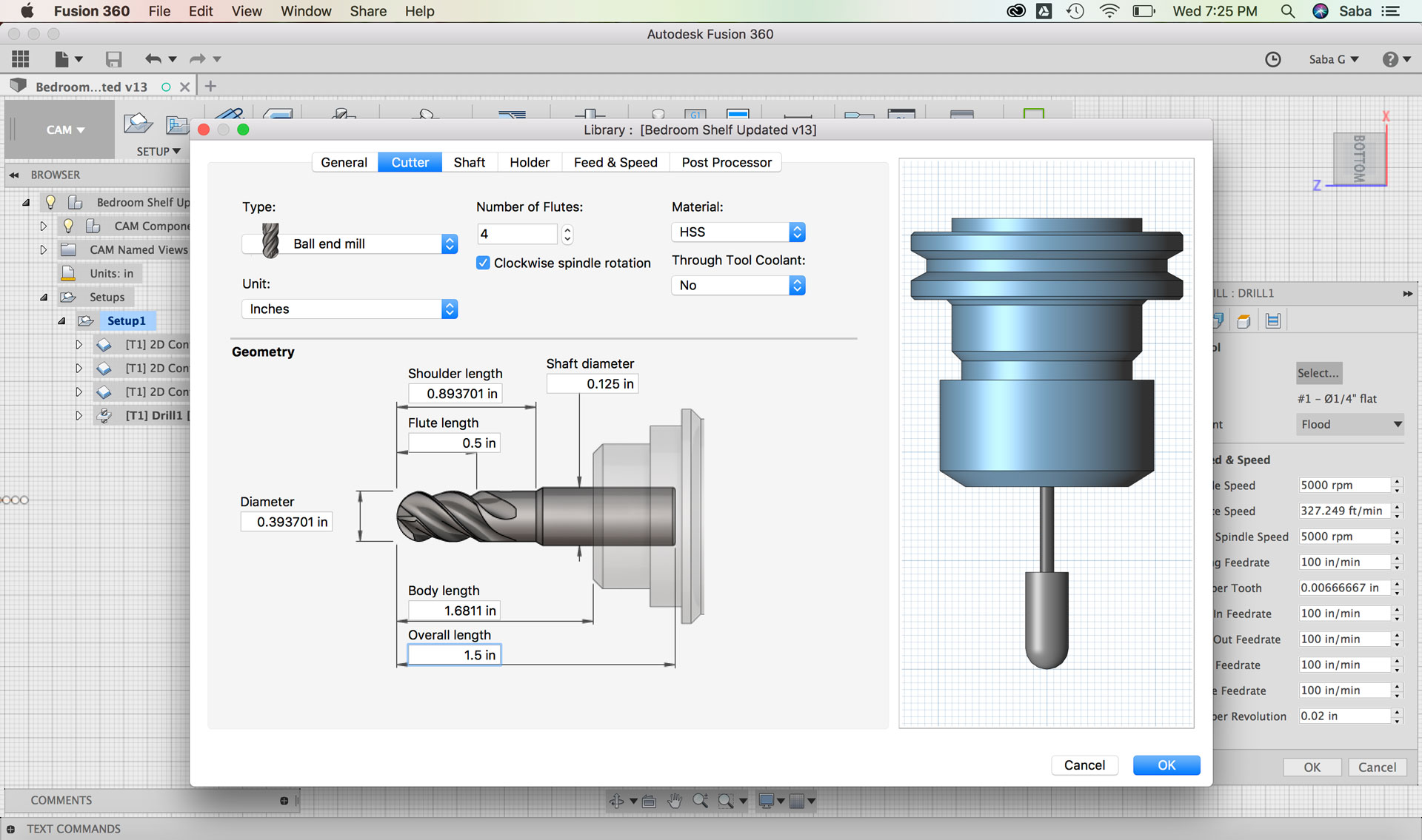
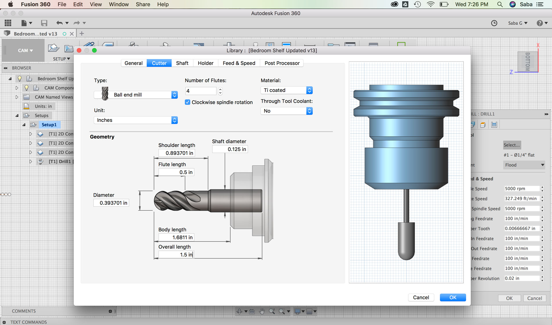
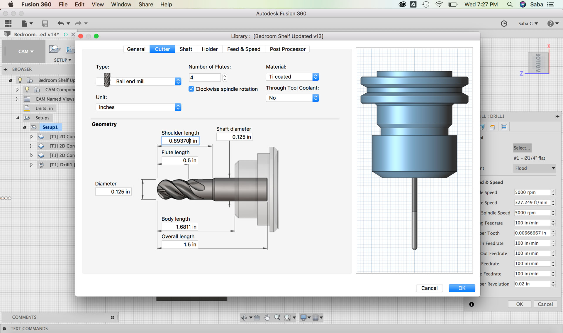
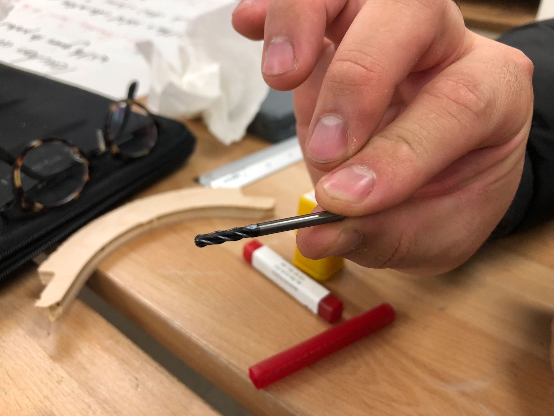
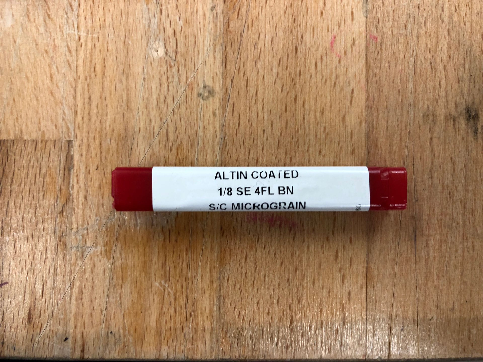
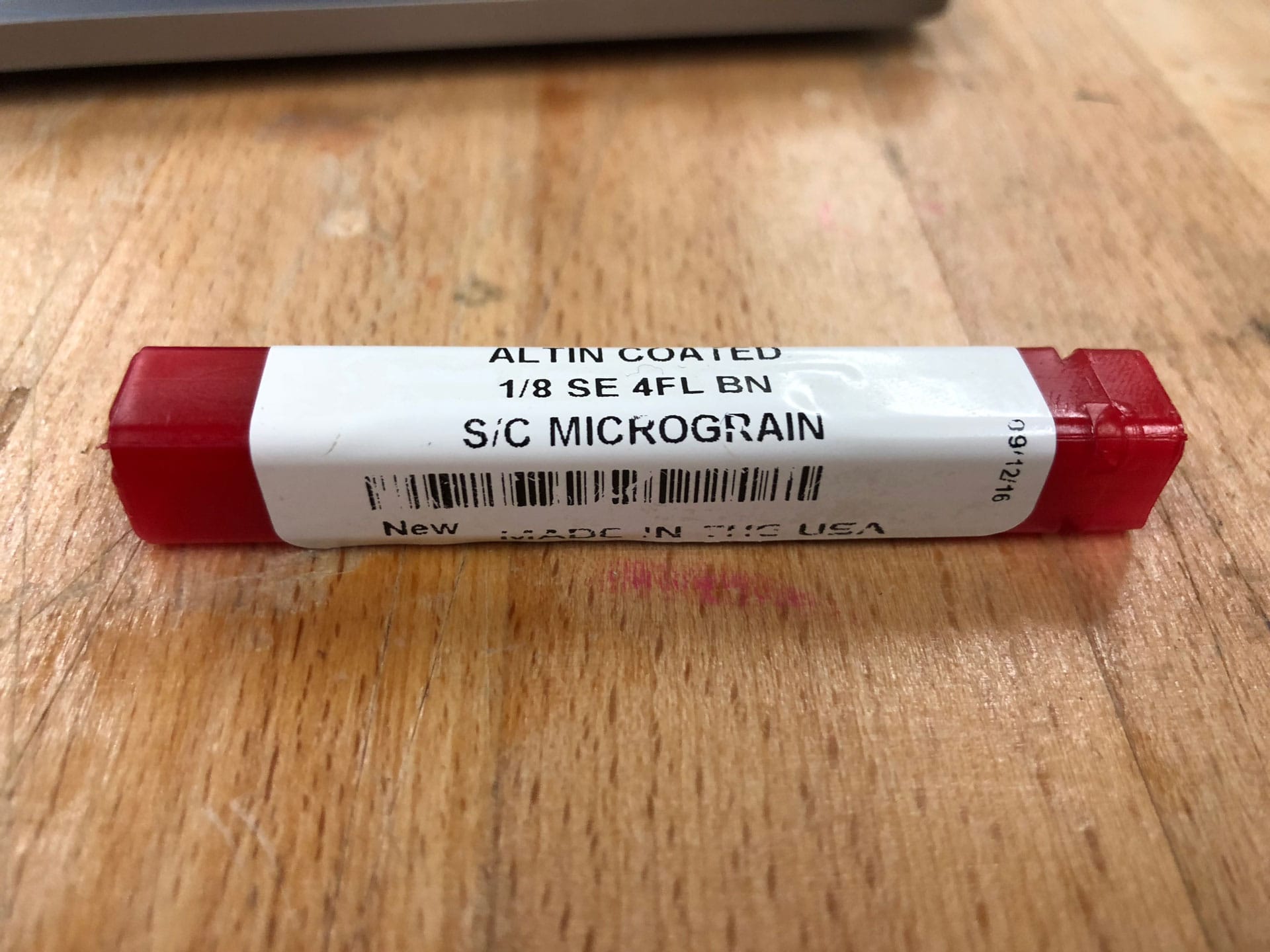
Update Tool: Ball end mill, overall length of 1.5”, Flute length of 0.5”, Shaft diameter and Diameter of 0.125”,4 Flutes, and Ti coated Material
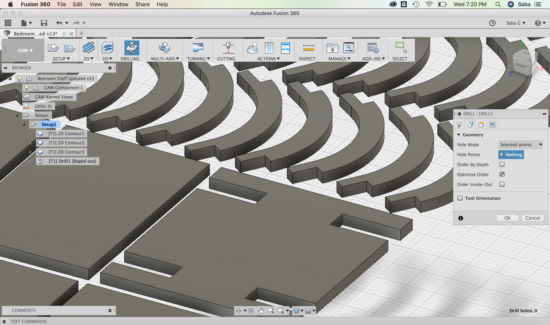
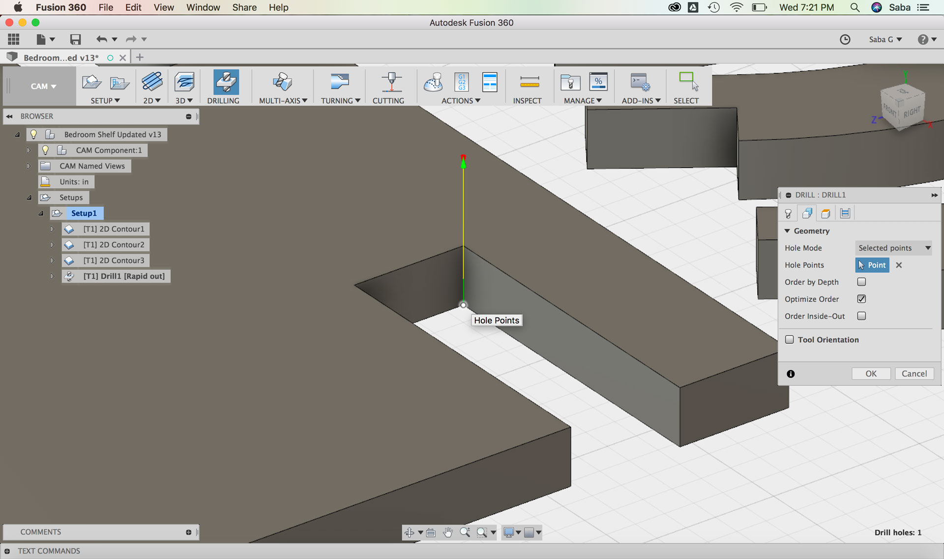
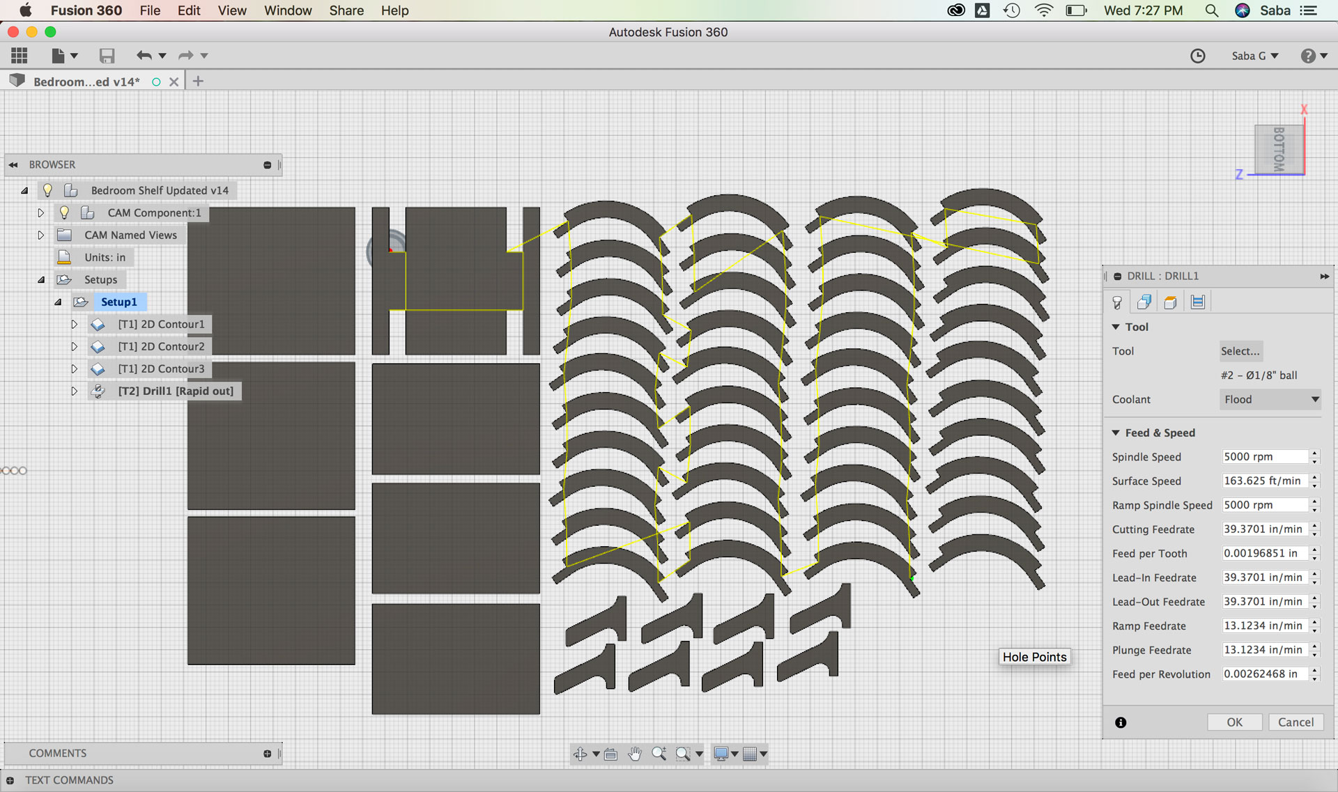
Under Geometry tab:
Hole Points: Select all interior right angle parts from the bottom of the drawing
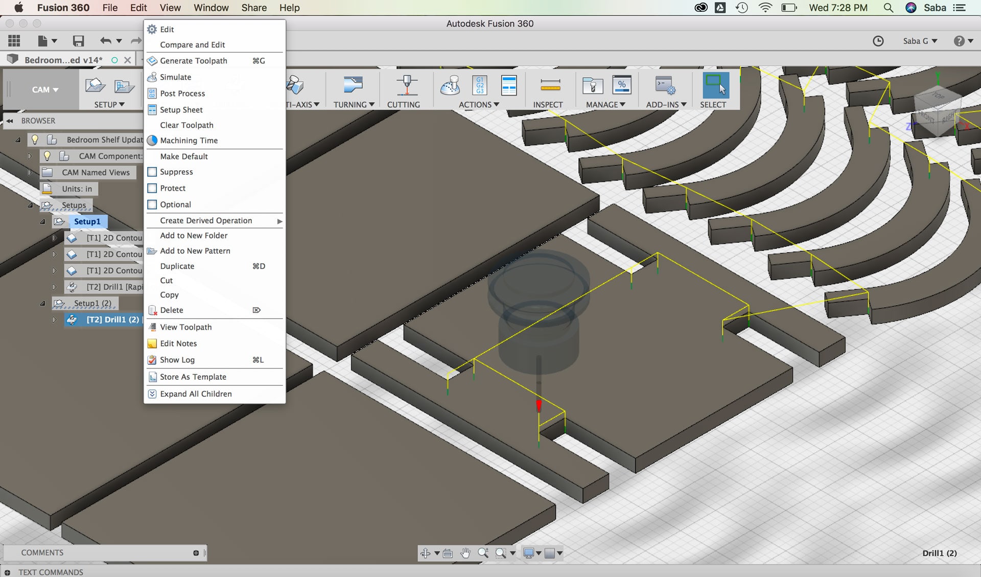
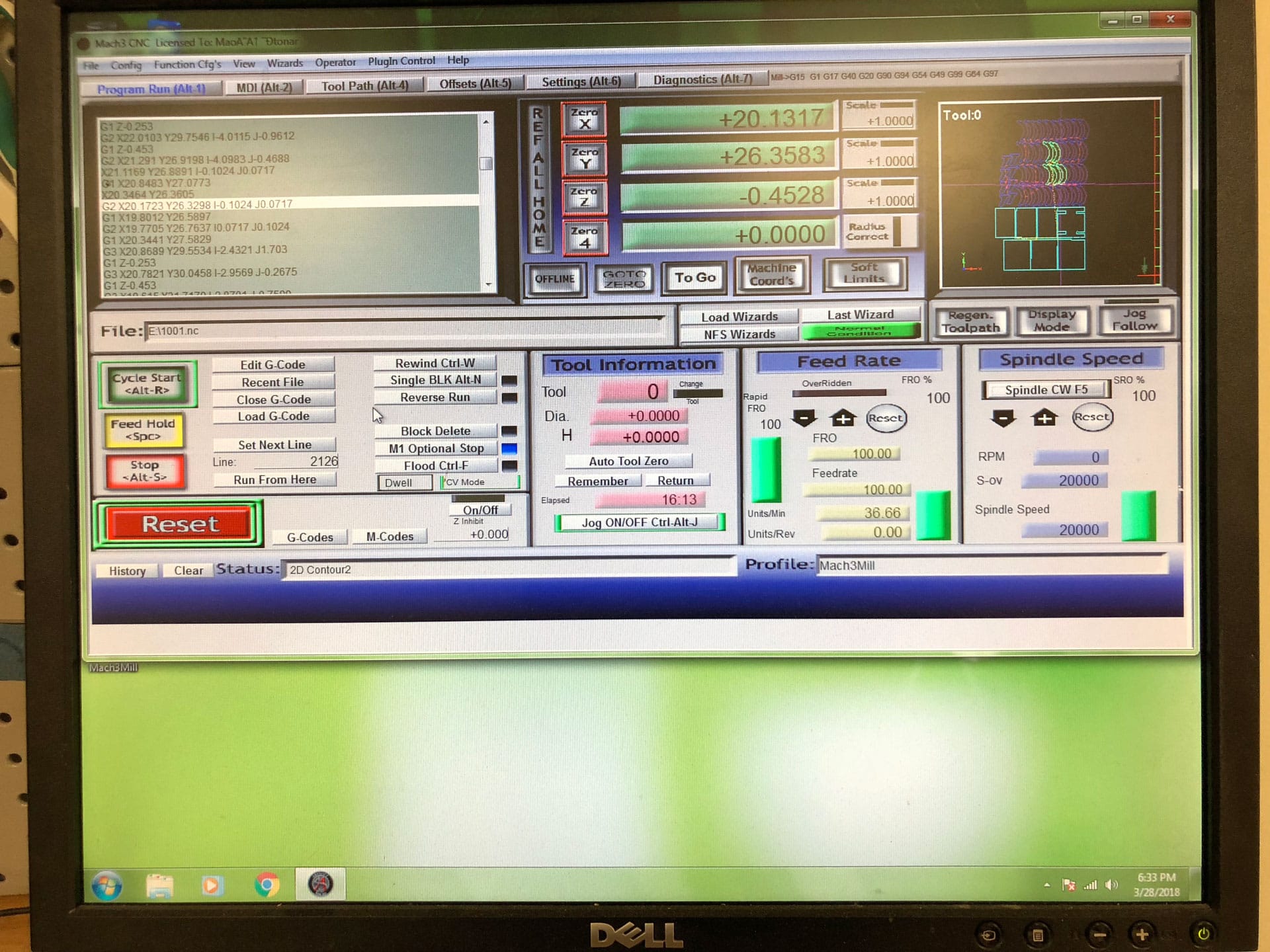
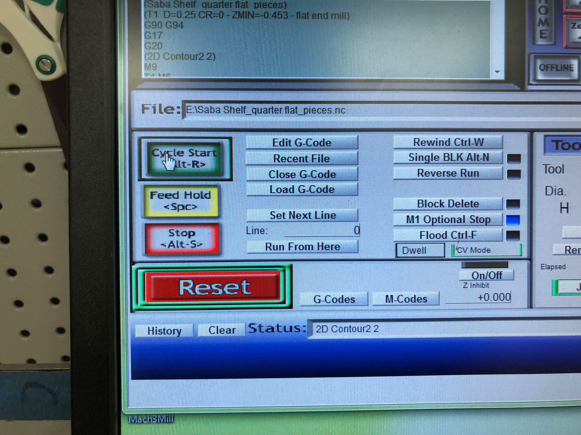
Given that these toolpaths would be using a different bit, I needed to have two separate g-code files. I duplicated the entire Setup menu with all 4 toolpaths and then deleted the other 3 toolpaths so that only the Drill toolpath remained in the second Setup. I updated Post Process details to Grbl and updated the Program number. Under Properties, I unchecked the G28 Safe retracts. I also deleted the Drill toolpath from the first Setup.
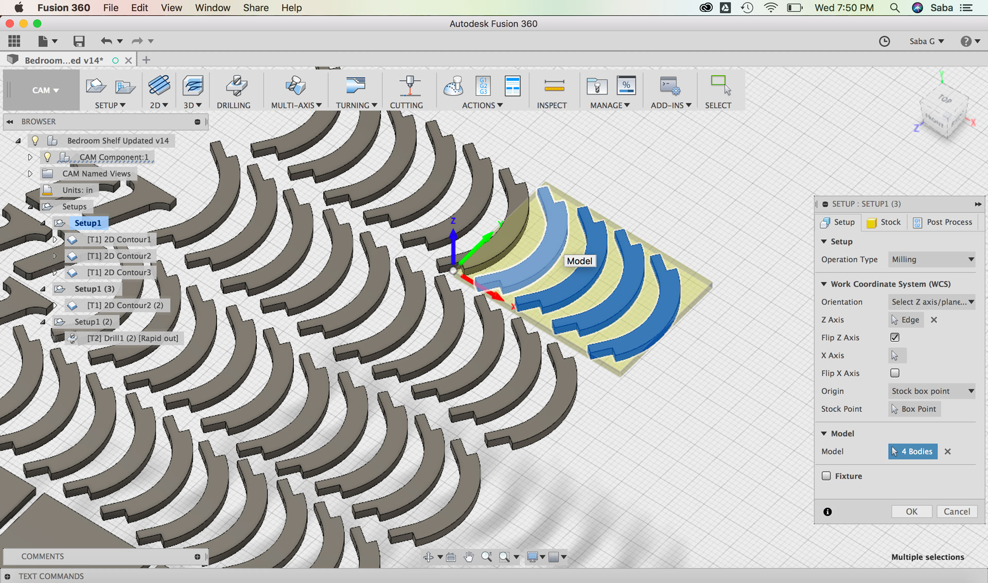
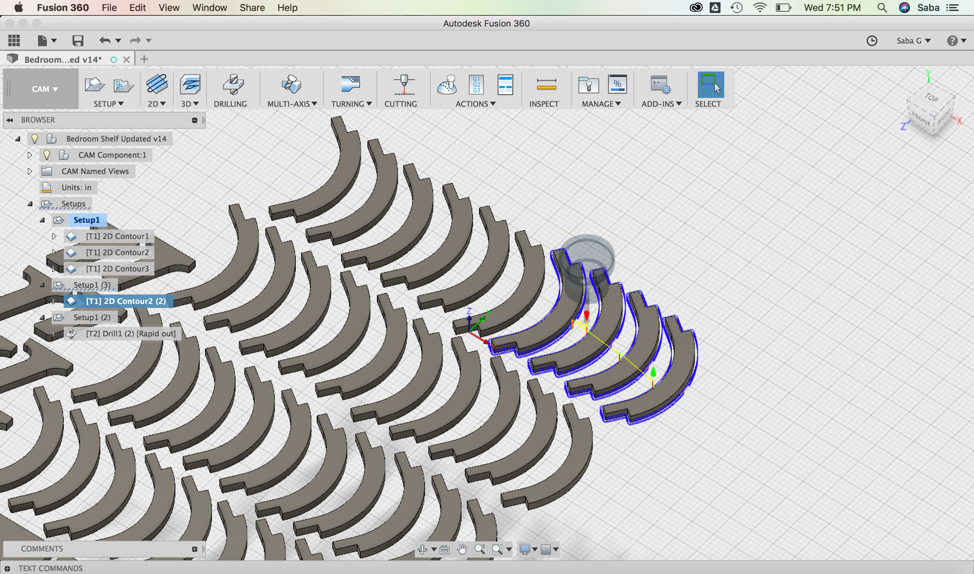
On hindsight, I should have cut some extra pieces in case of any broken pieces during the machining process, but I didn’t. After the machining process, I created a separate cut file with a toolpath with only 4 pieces. In order to create this, I duplicated Setup 1 and only kept the 2D Contour2 toolpath and modified the Model to include only 4 Bodies. I Generated the Toolpath and updated the Post Process and created a new NC file.
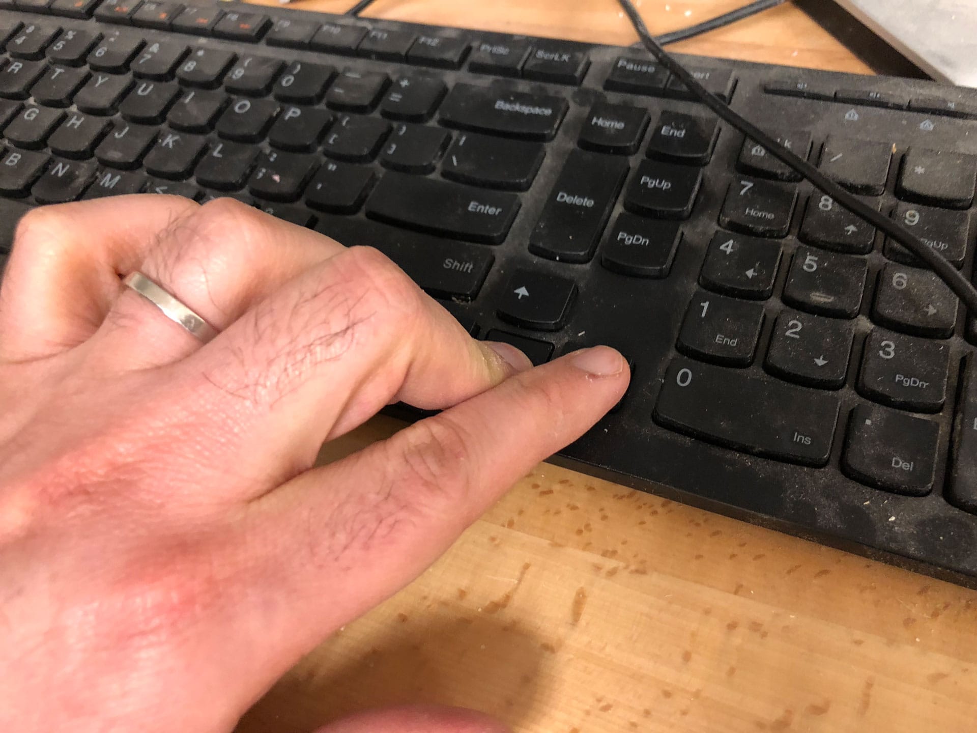
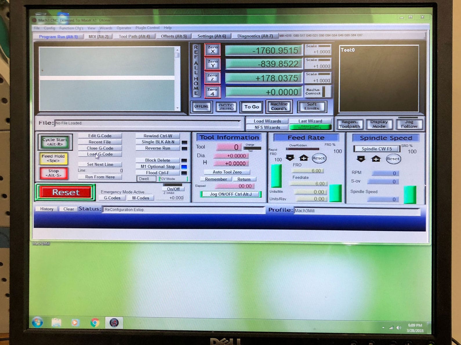
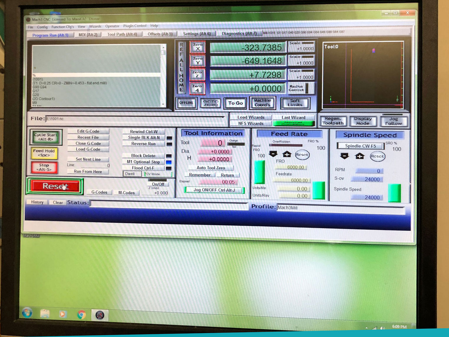
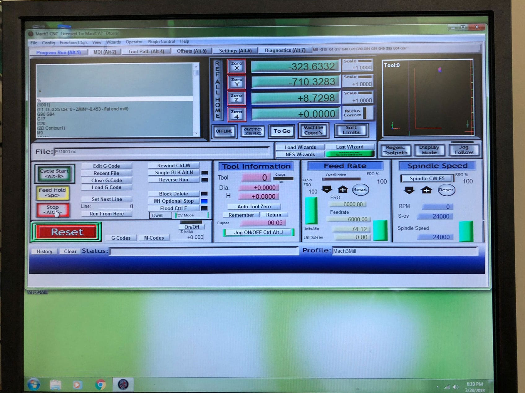
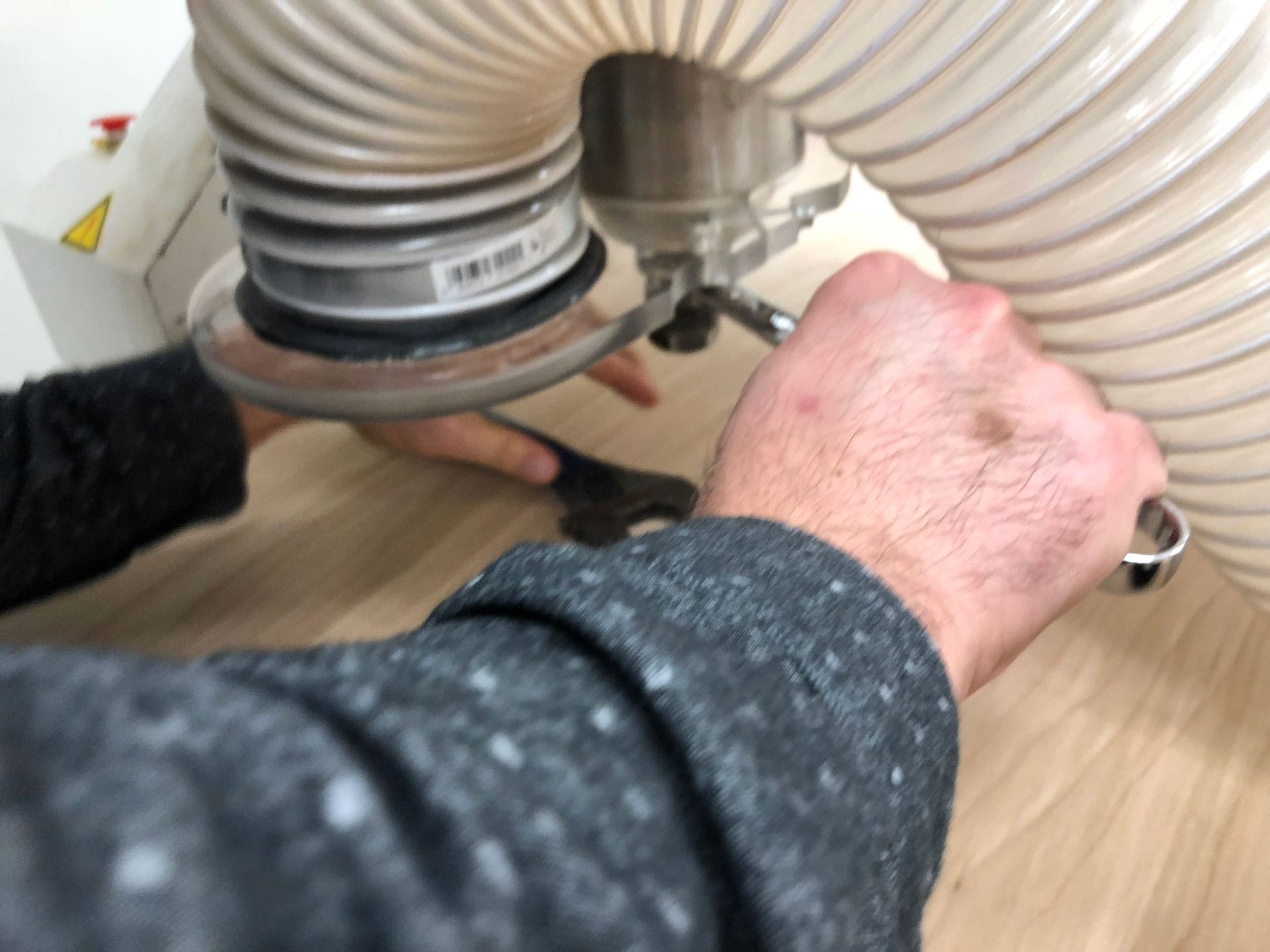
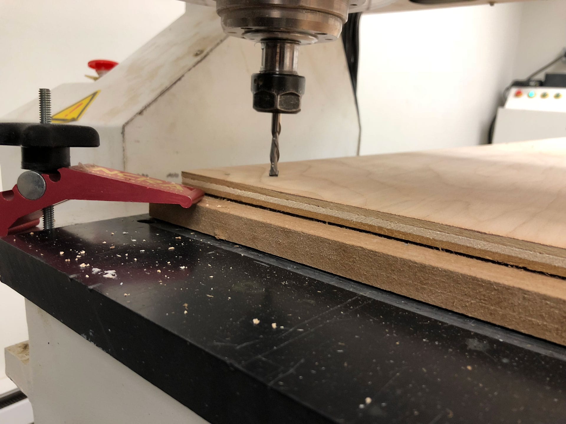
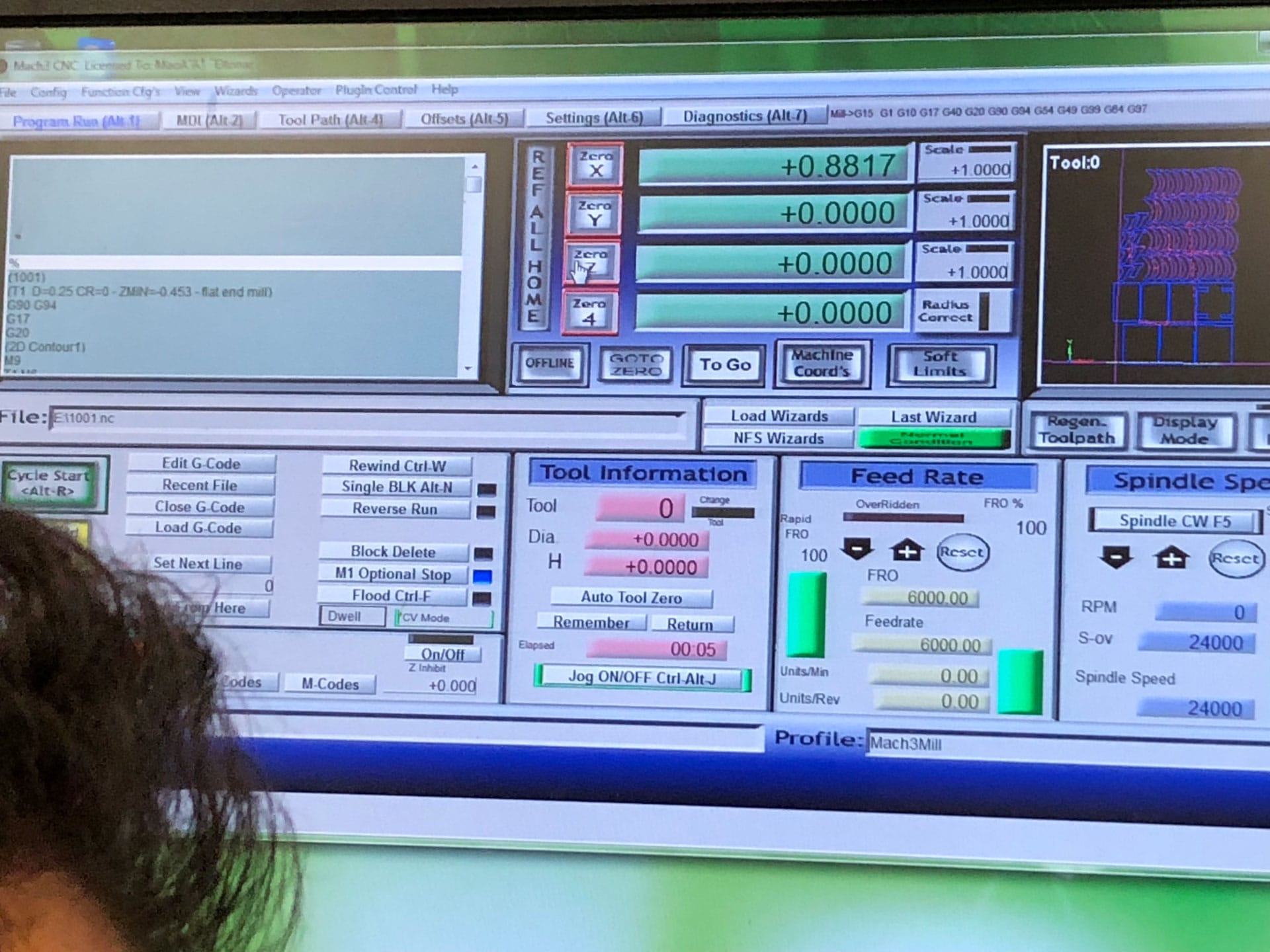
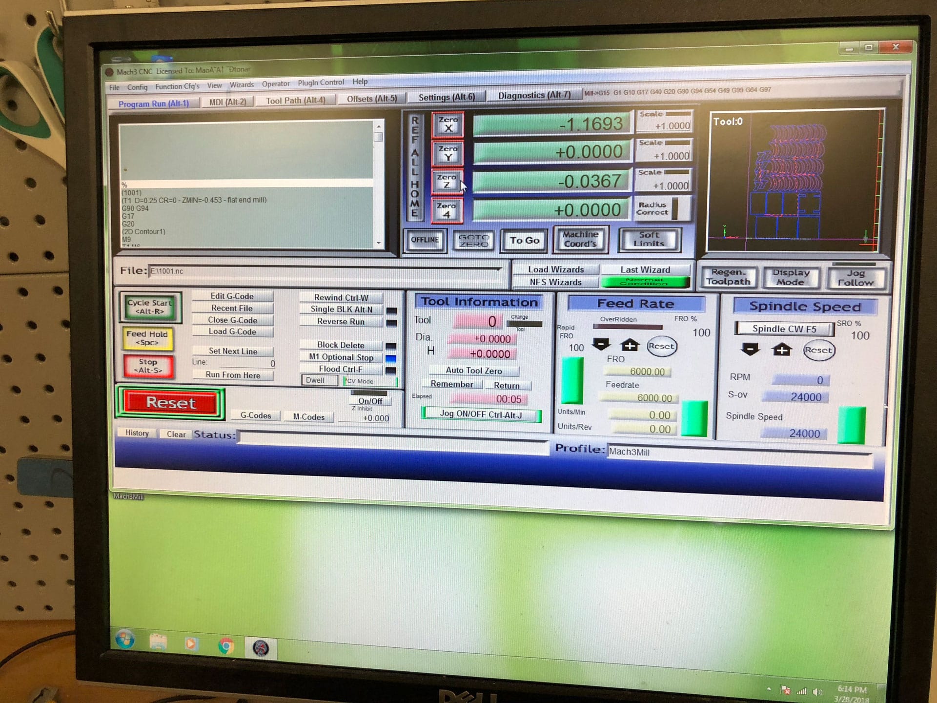
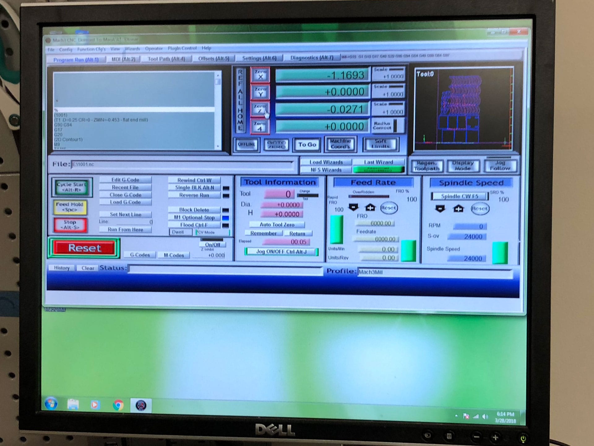
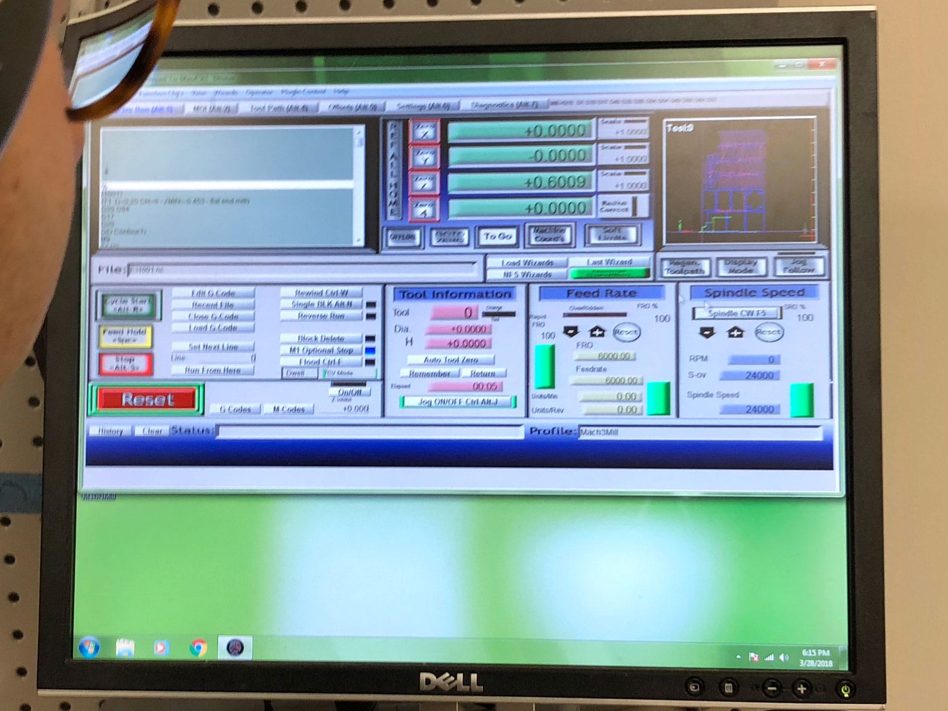
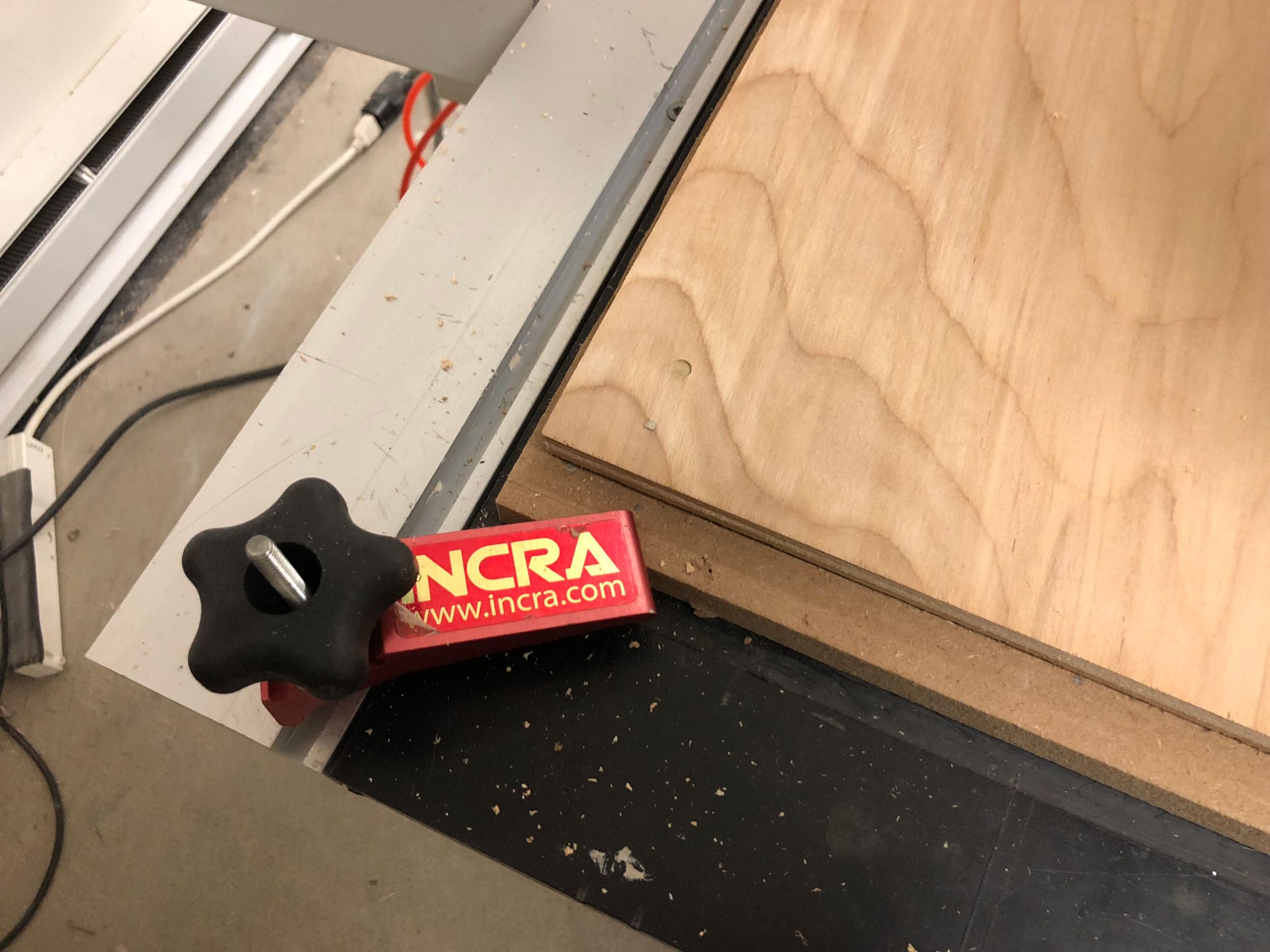
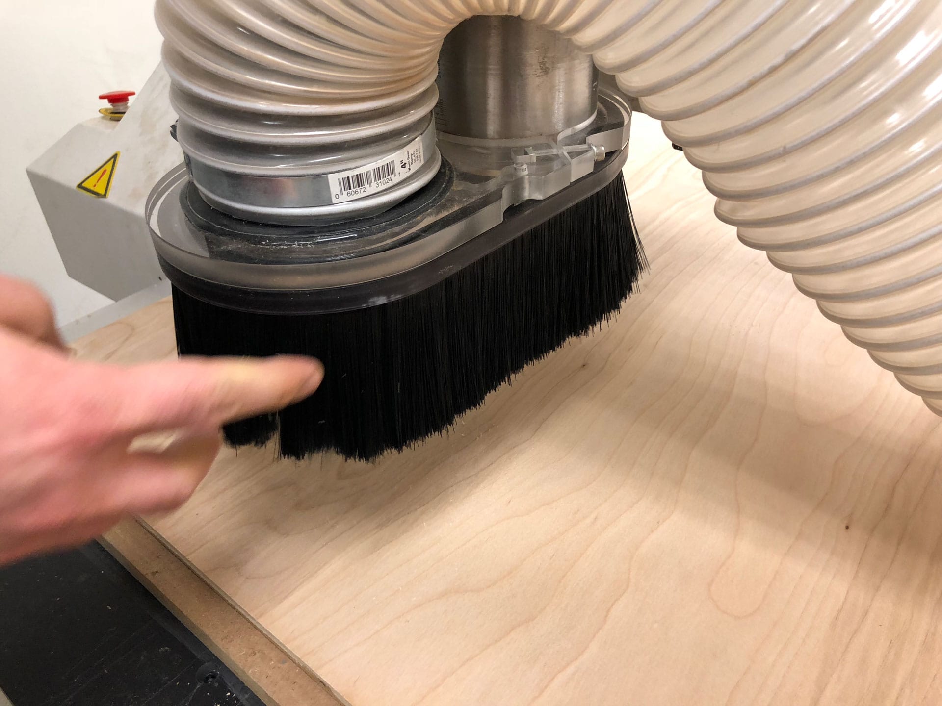
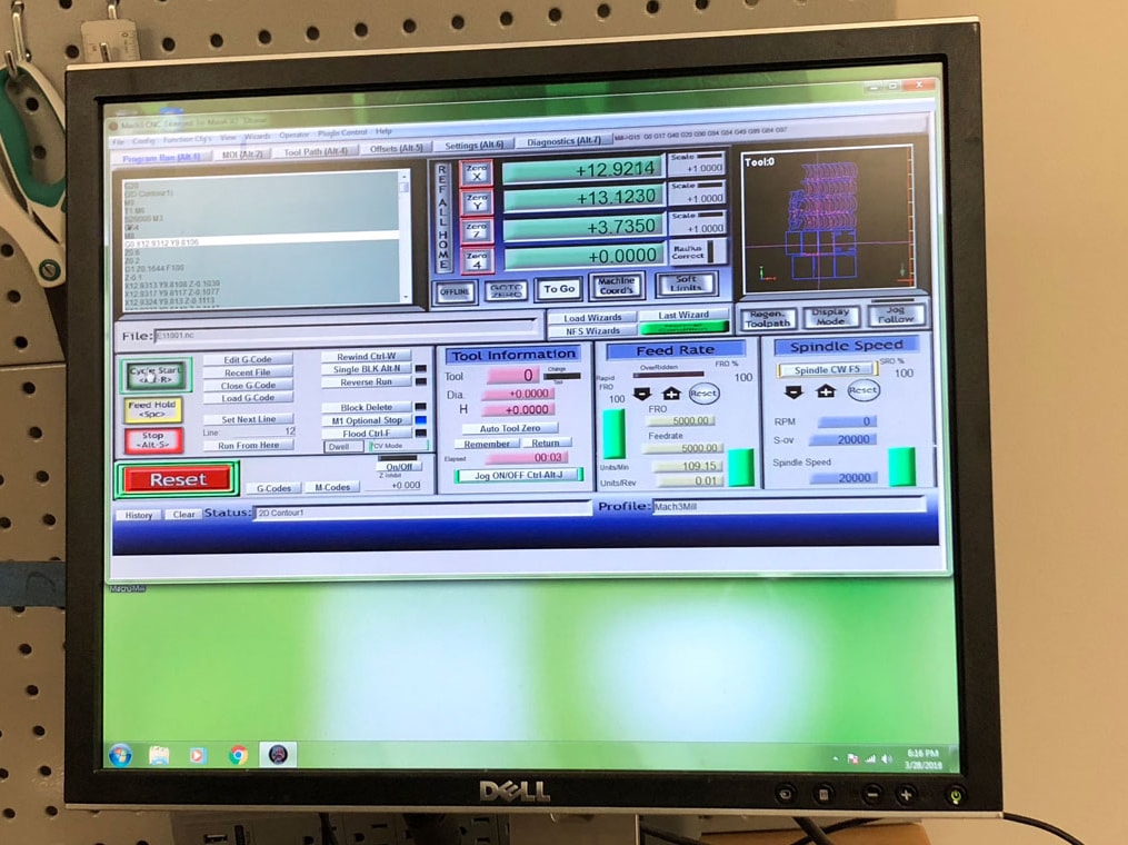
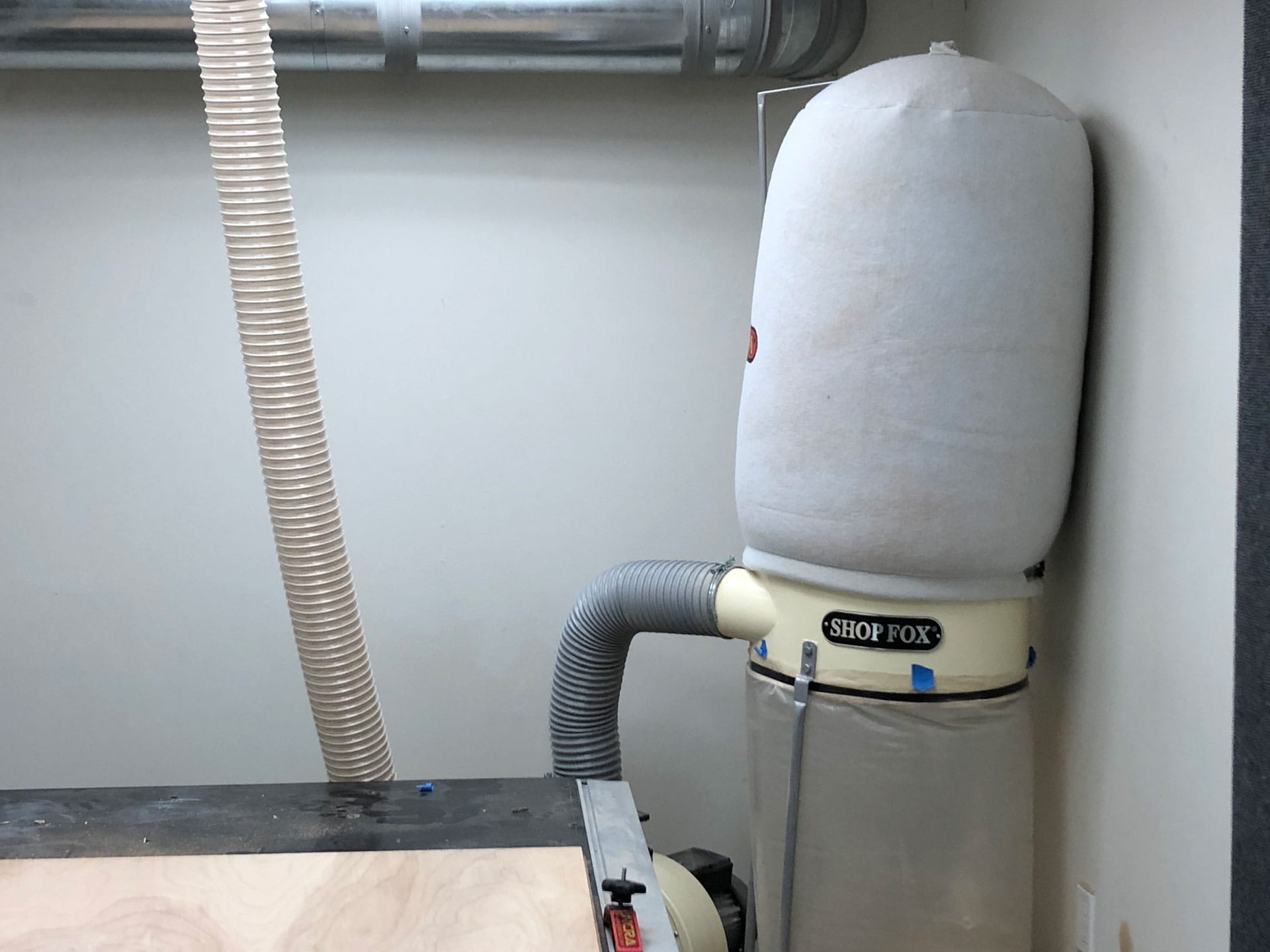
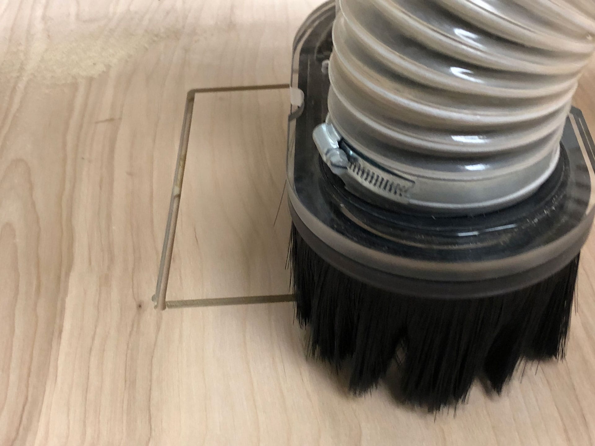
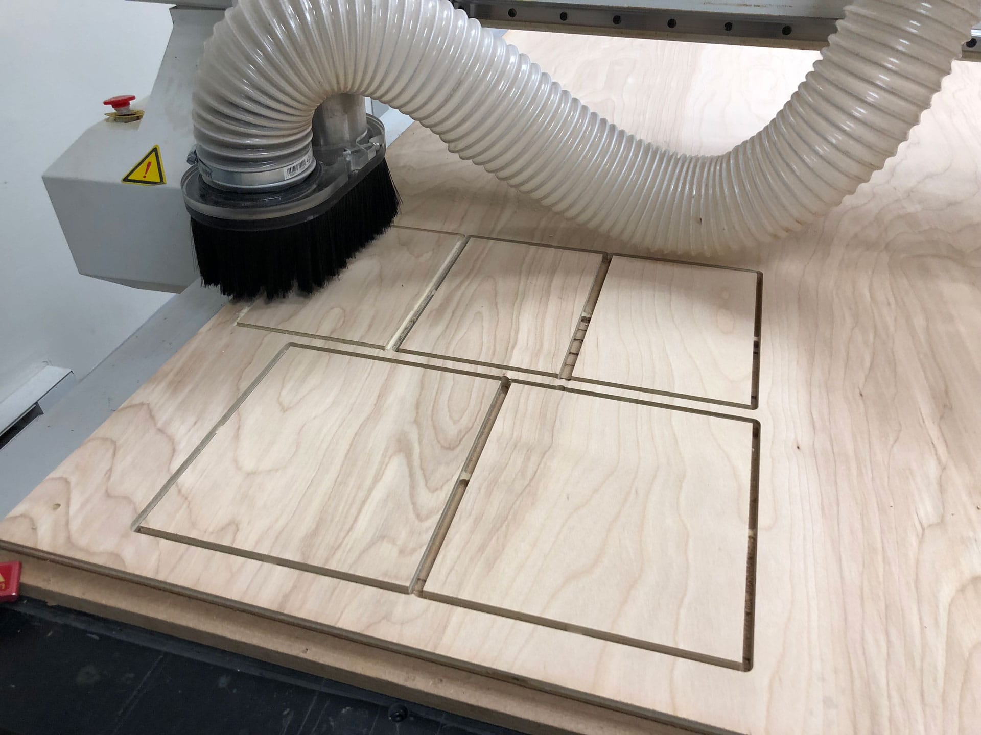
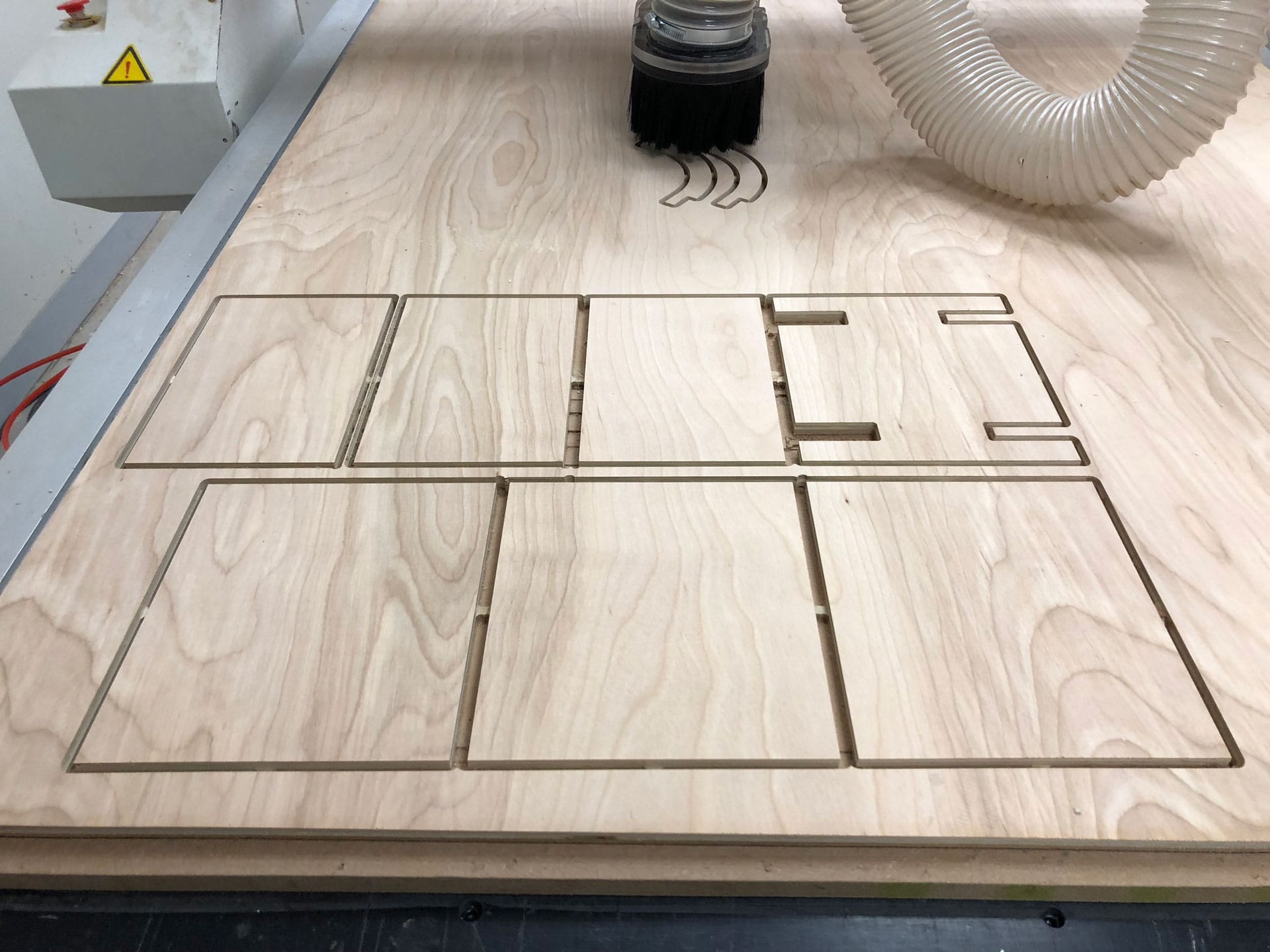
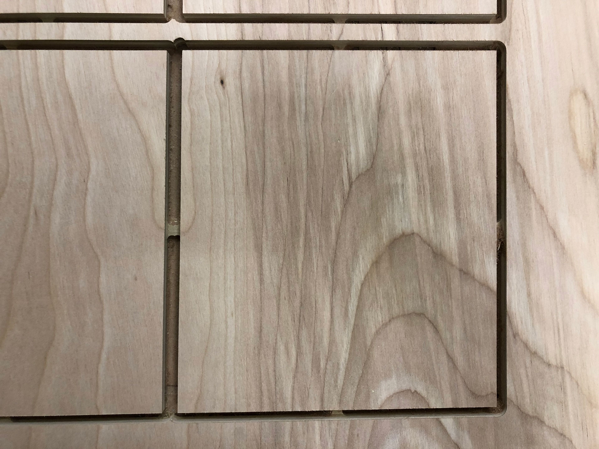
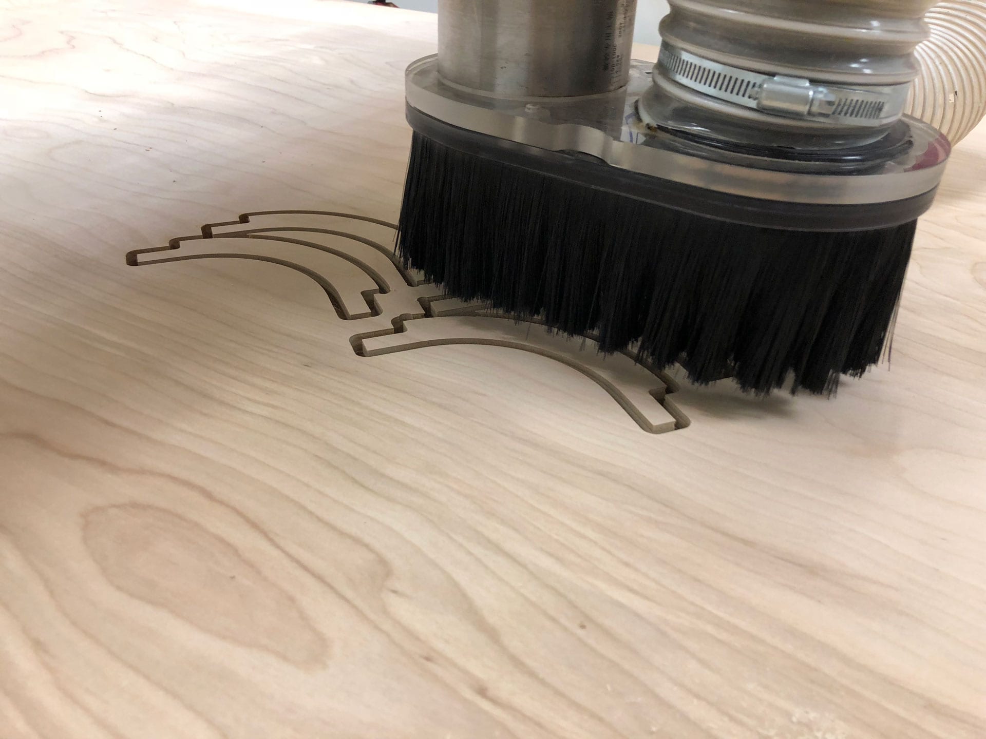
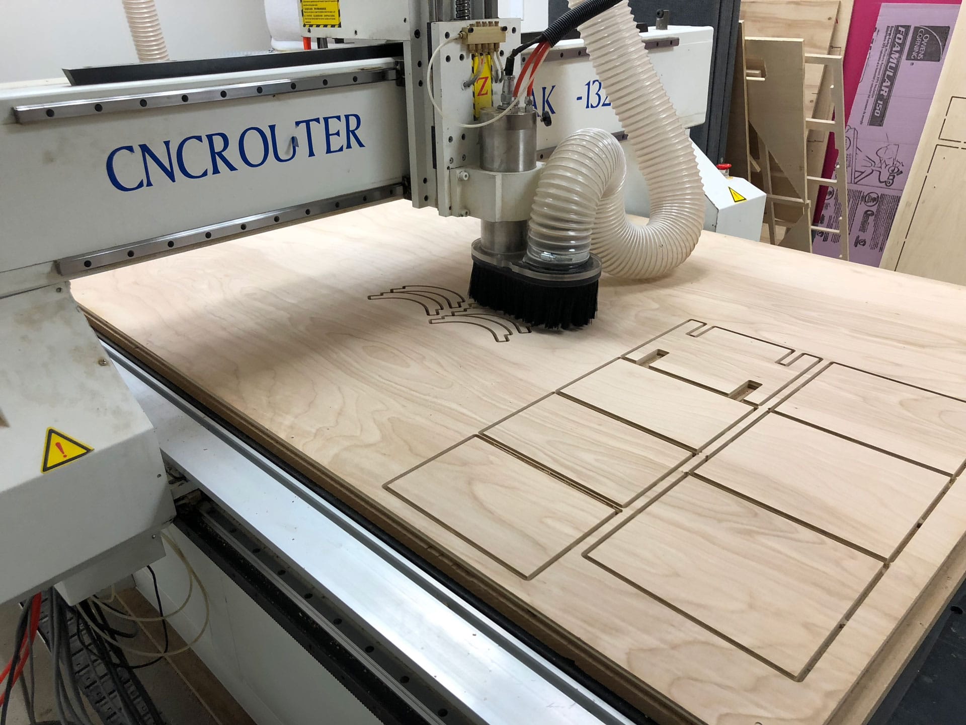
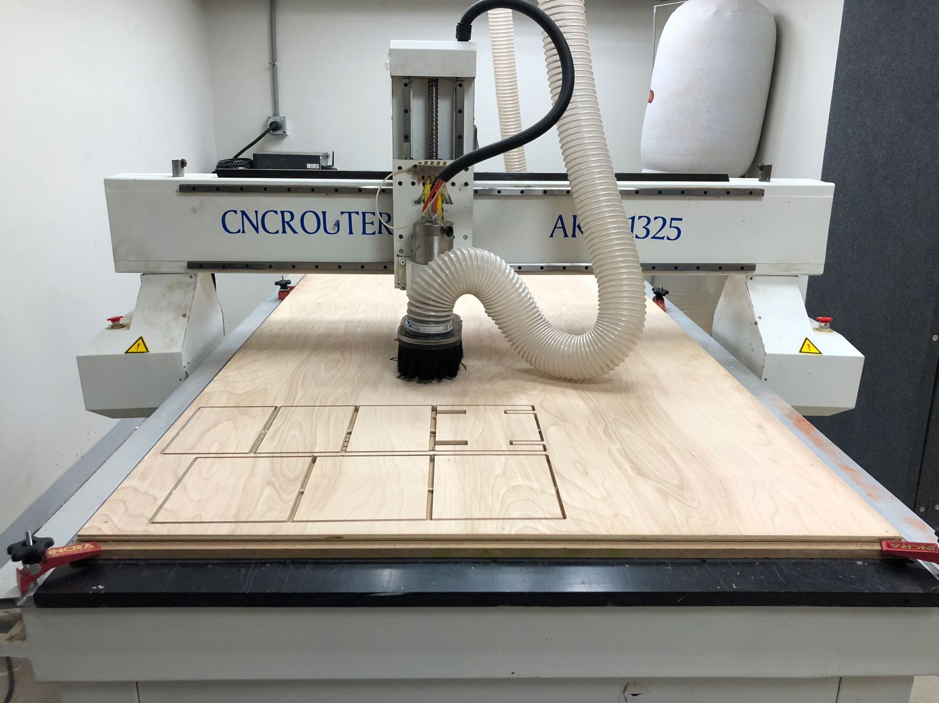
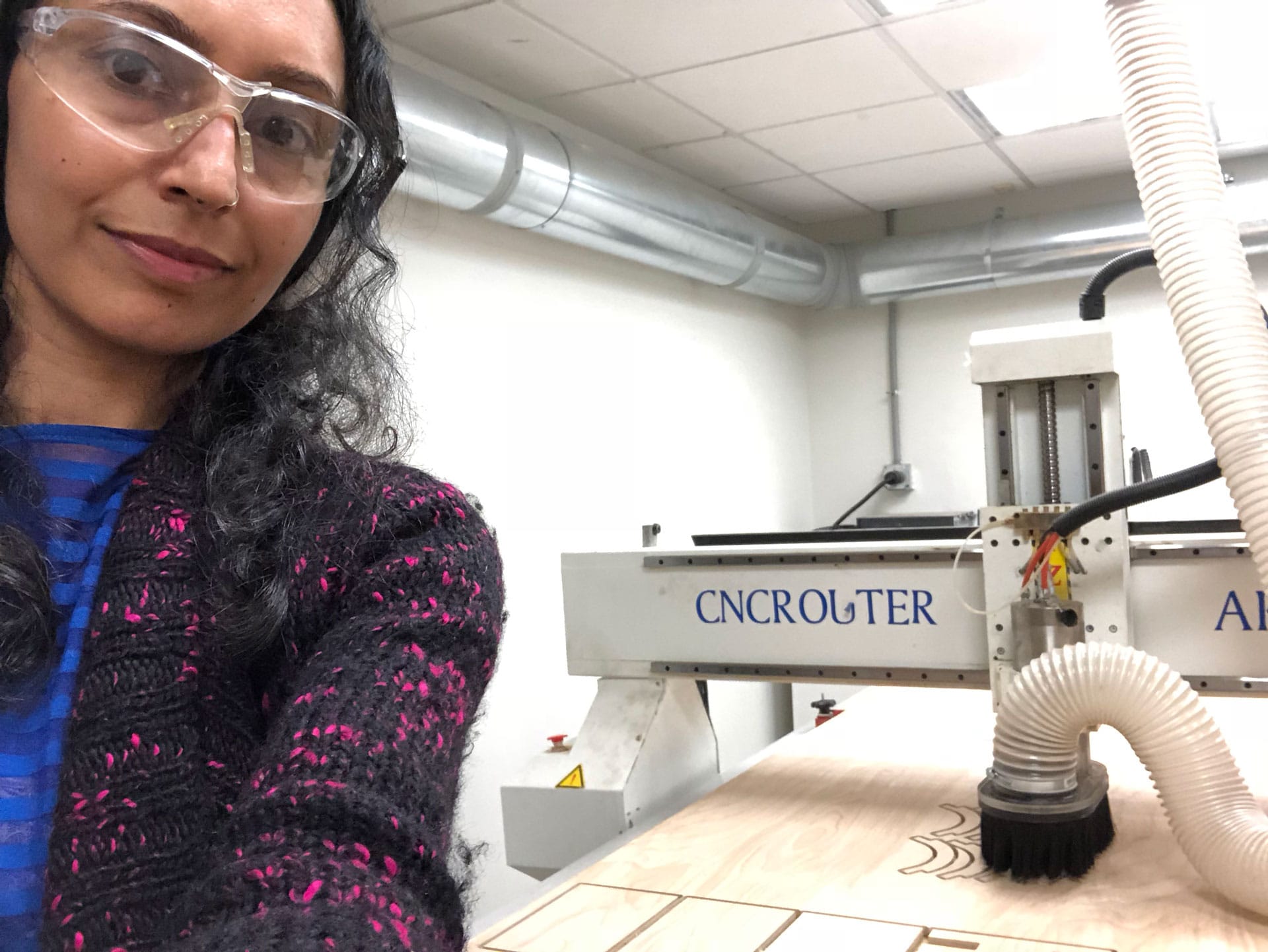
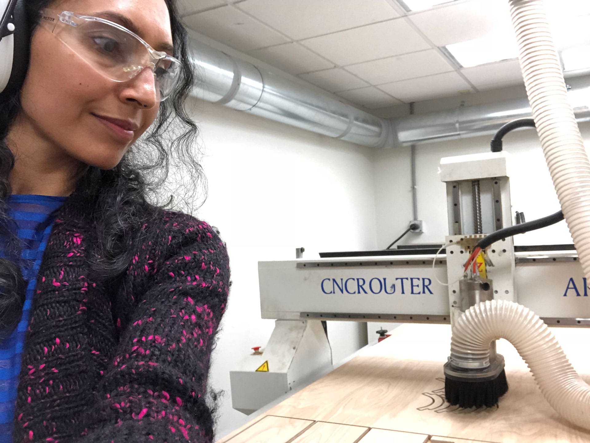
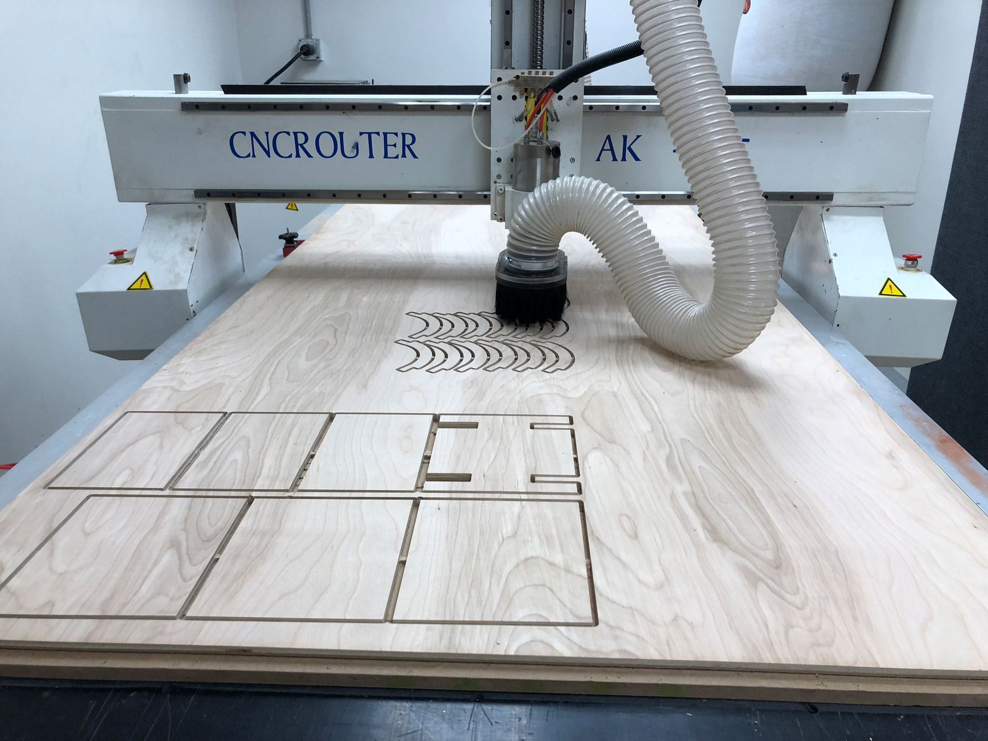
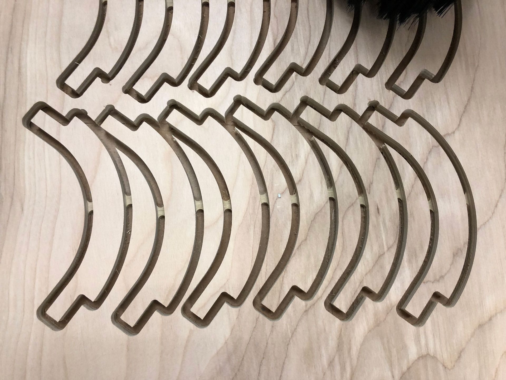
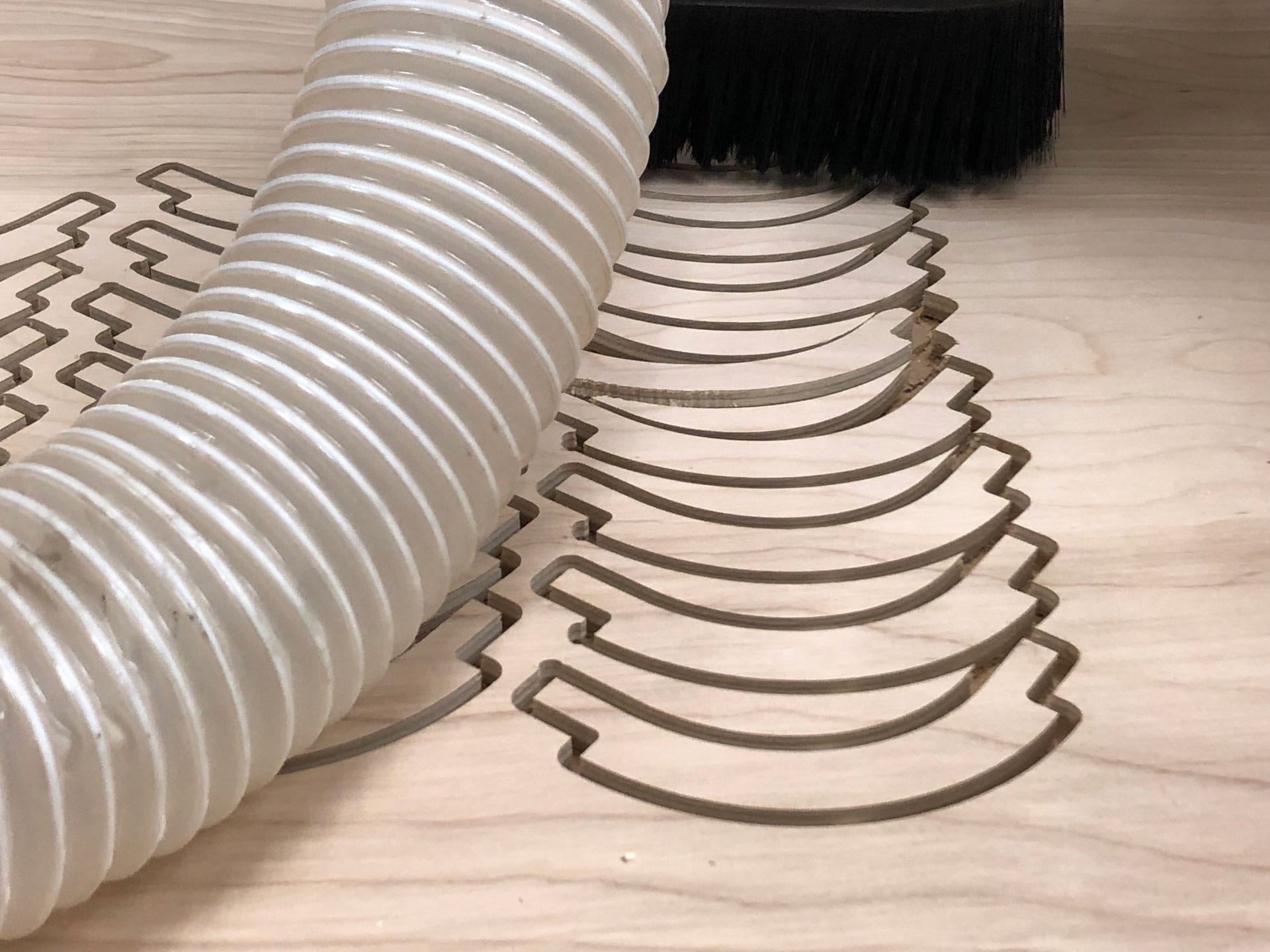
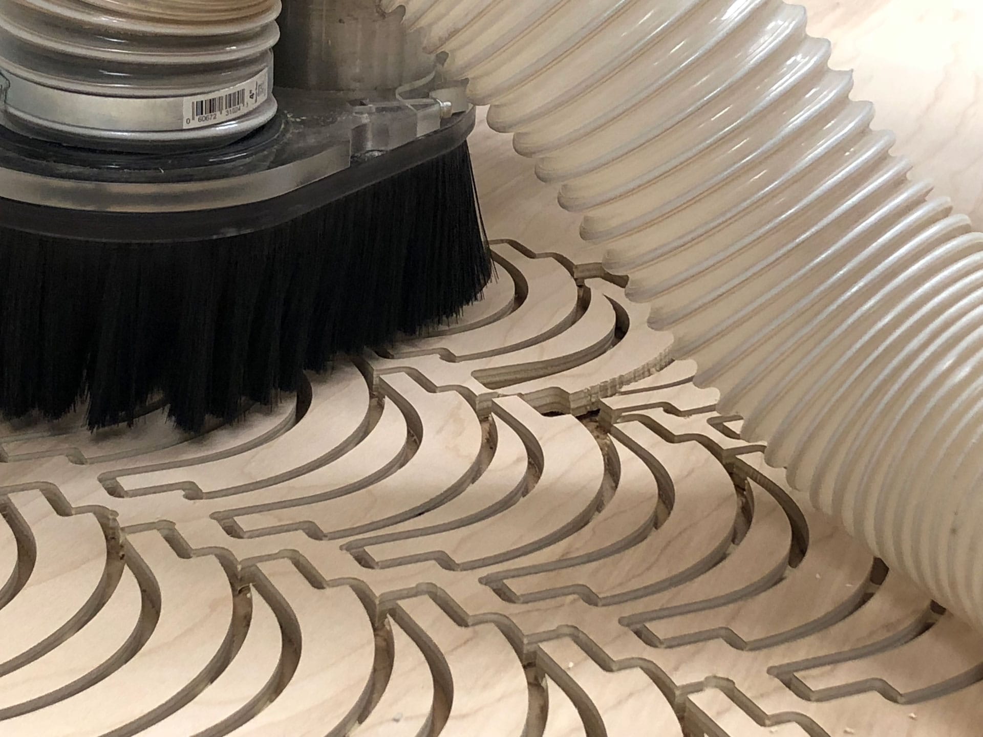
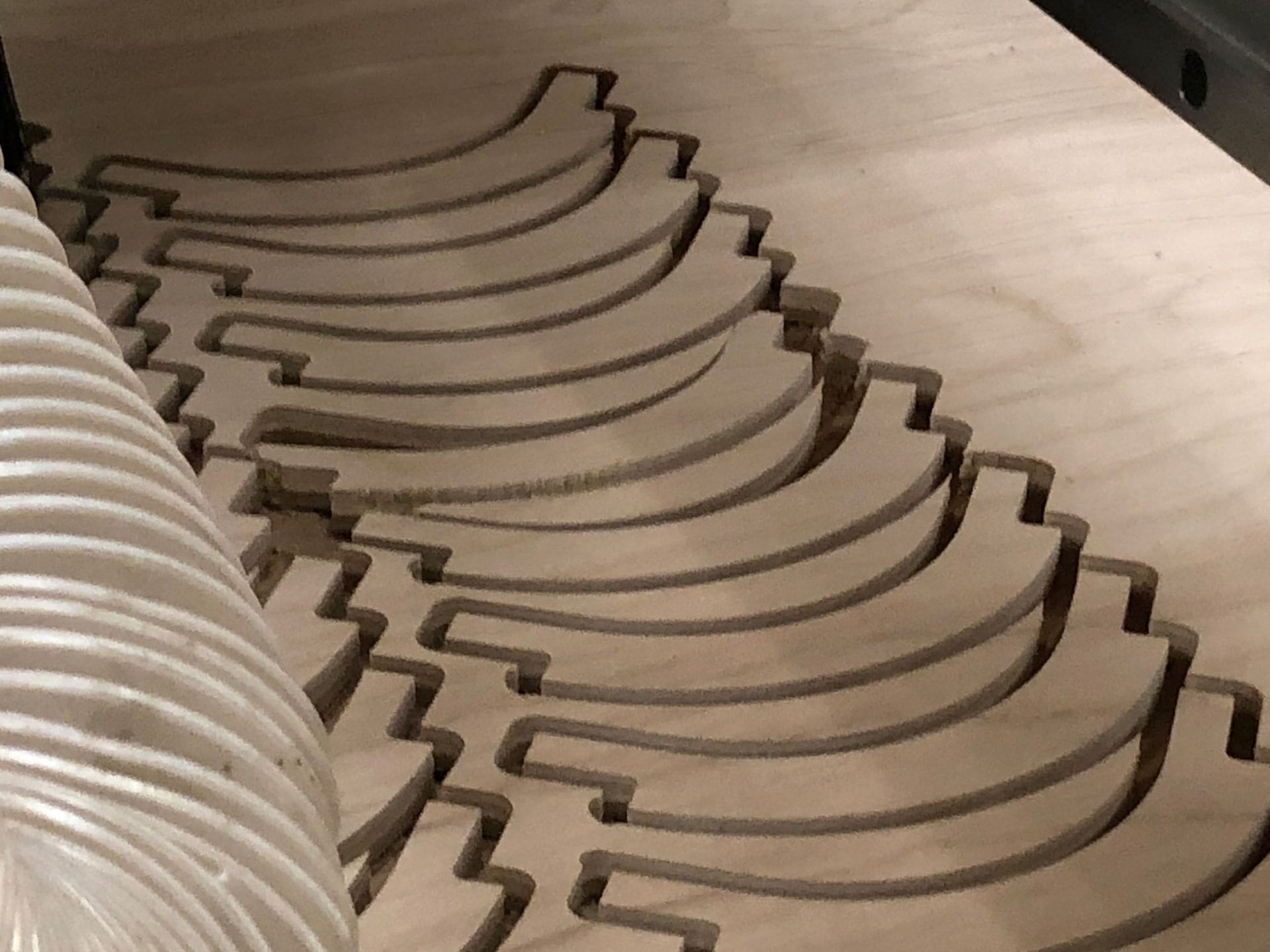
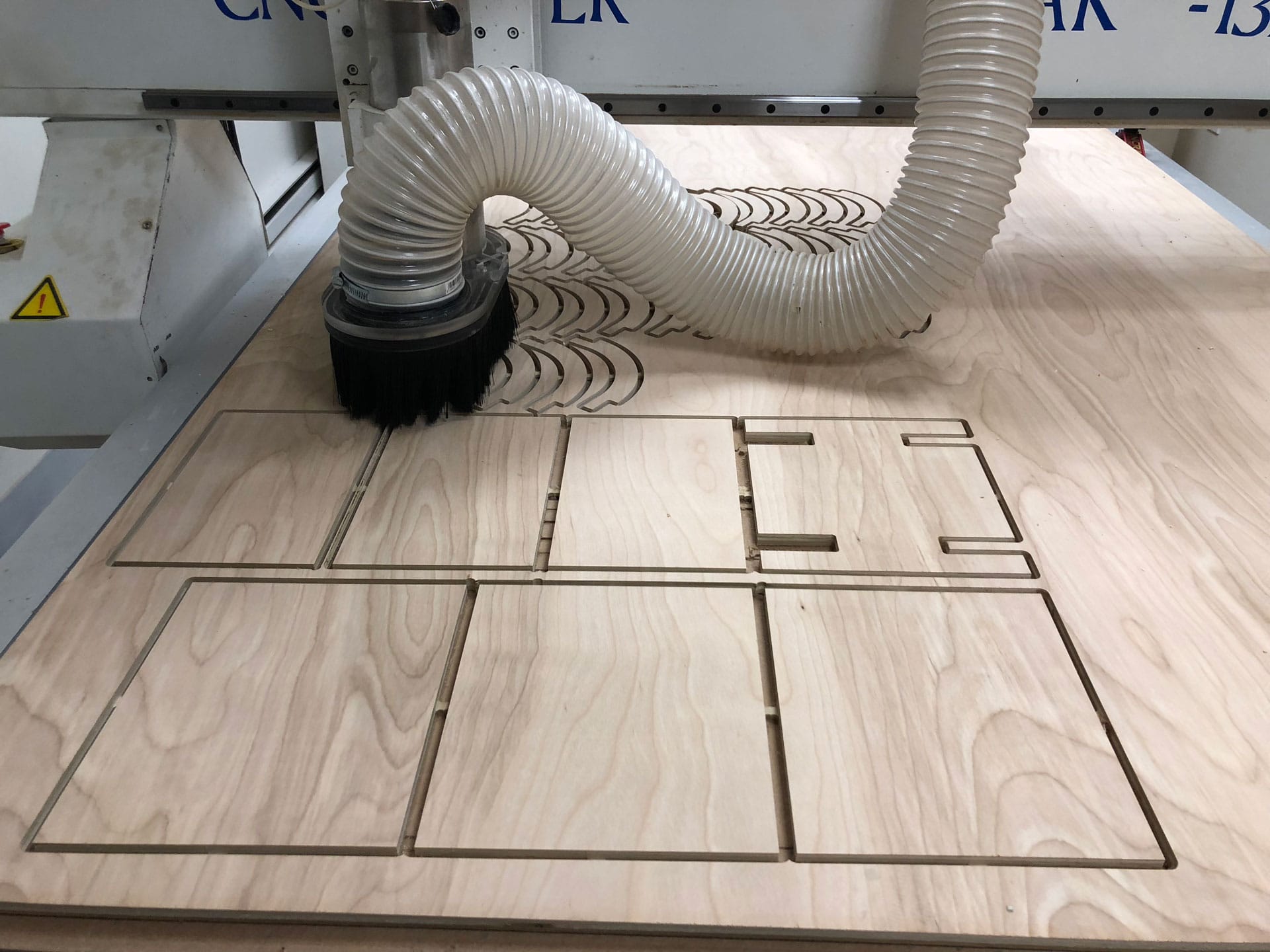
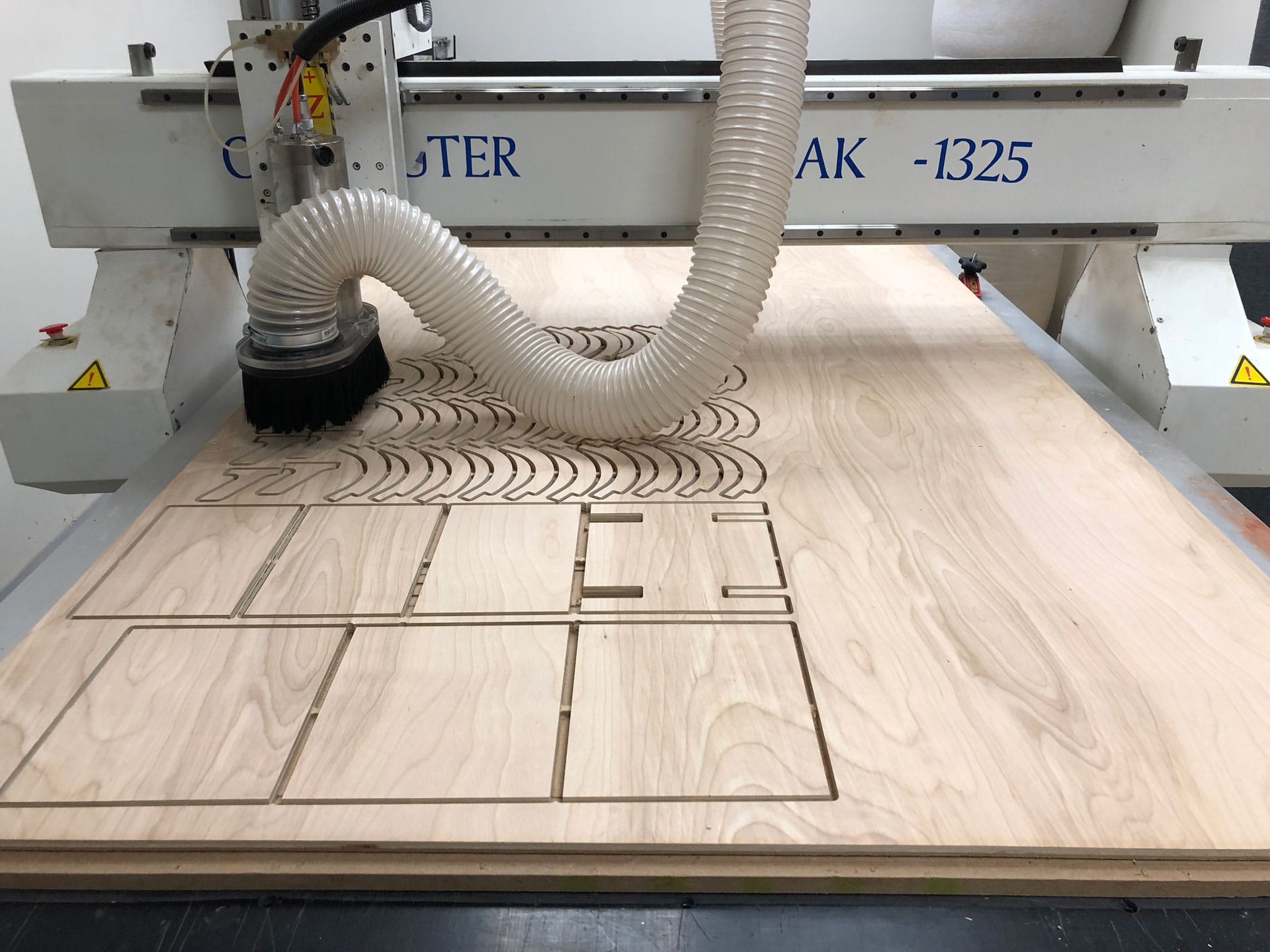
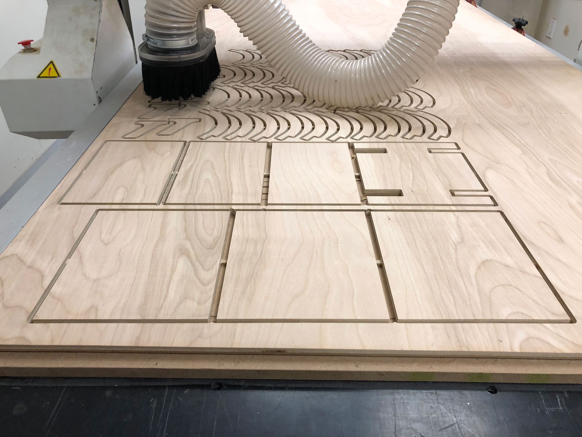
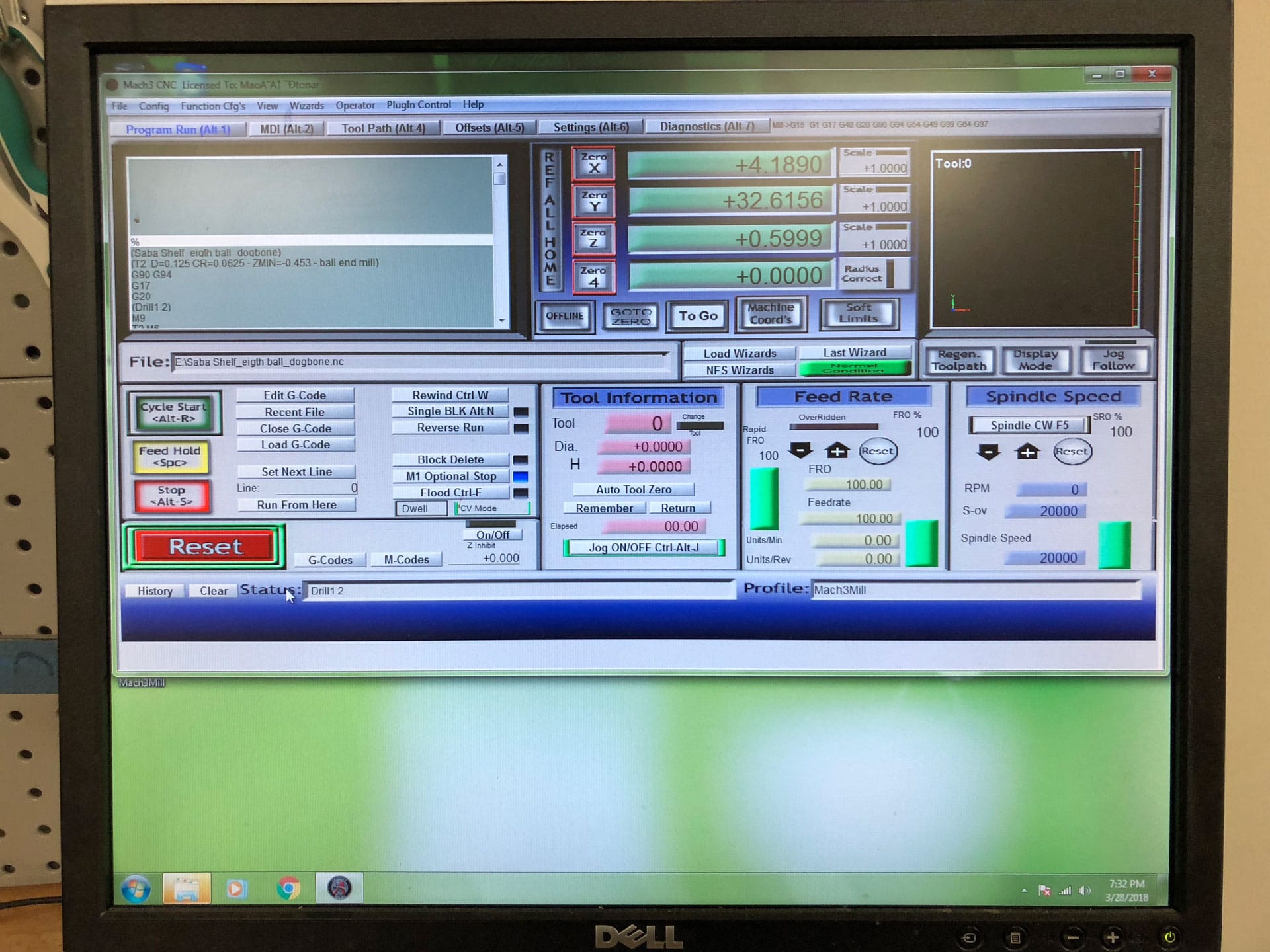
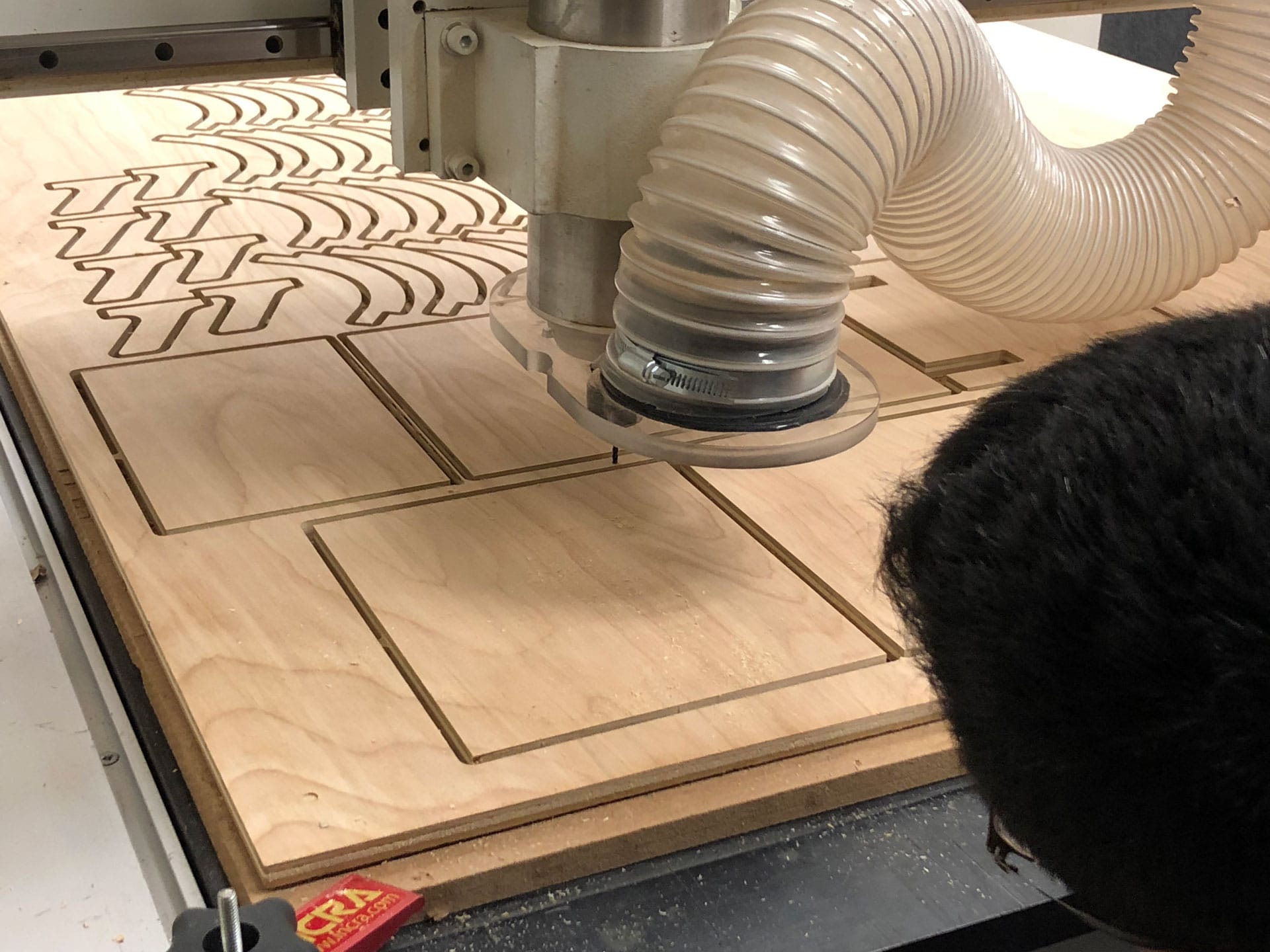
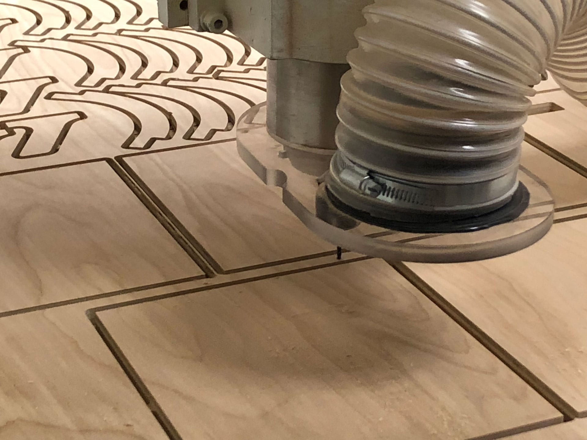
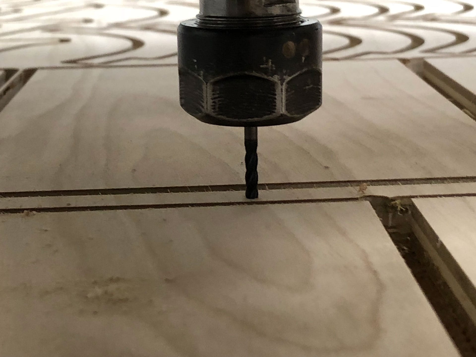
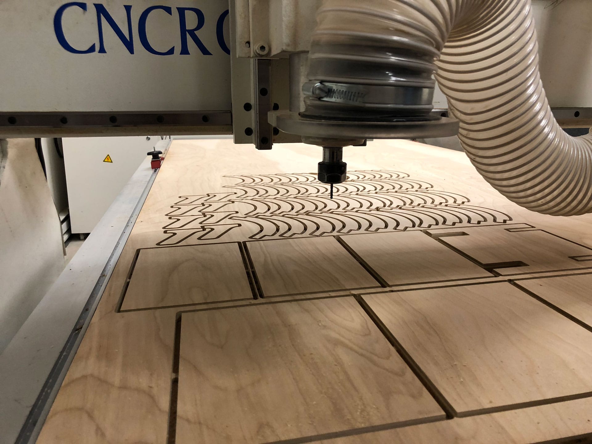
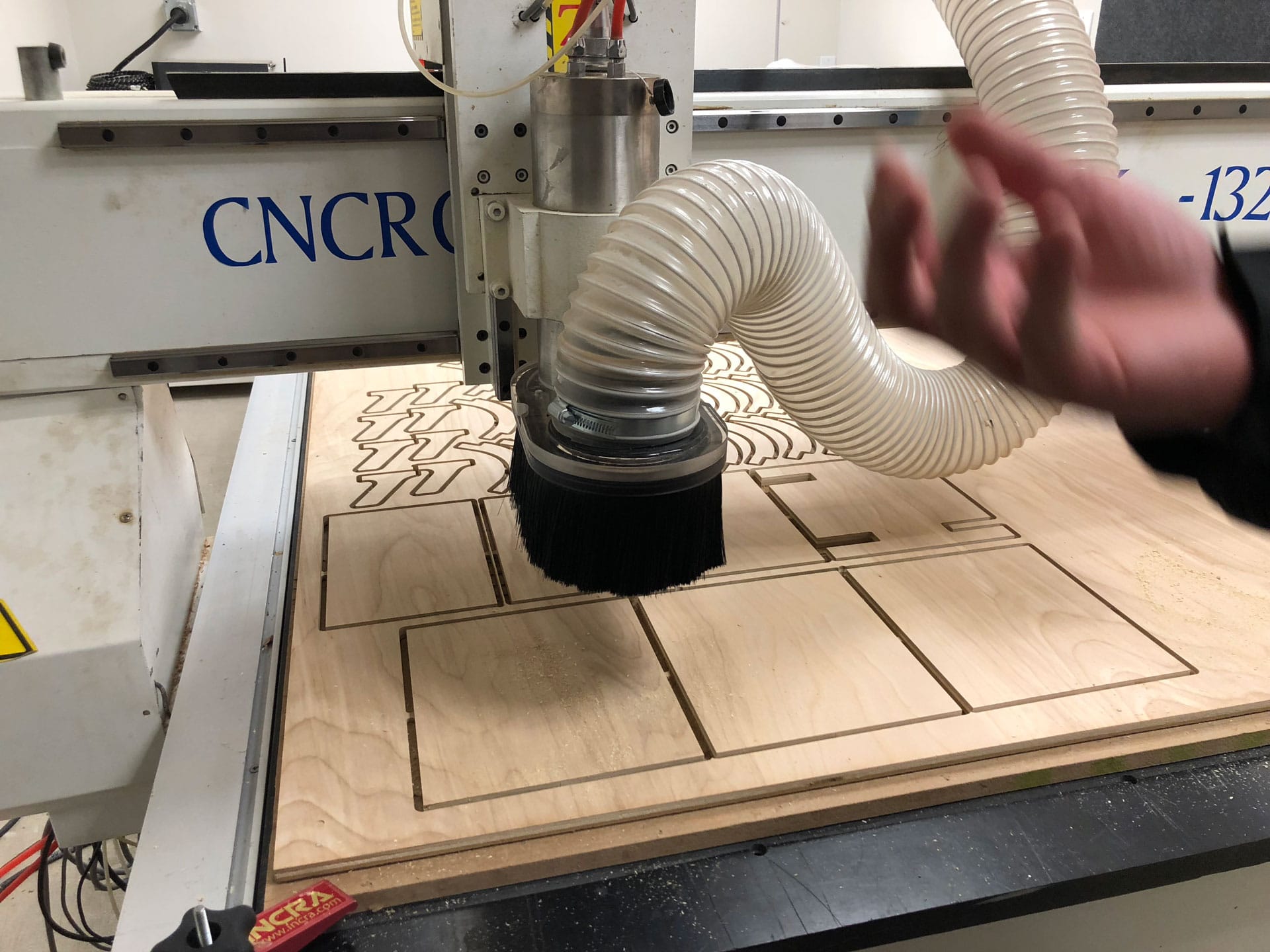
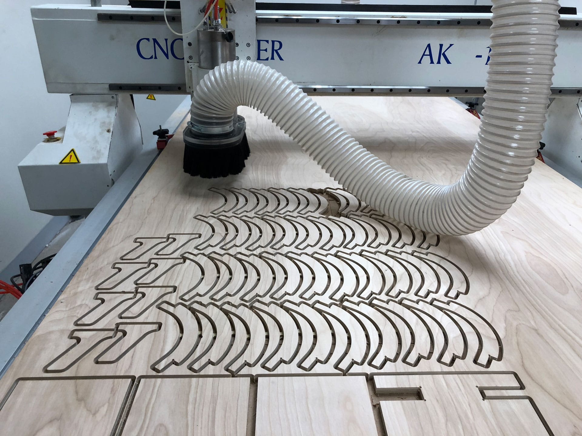
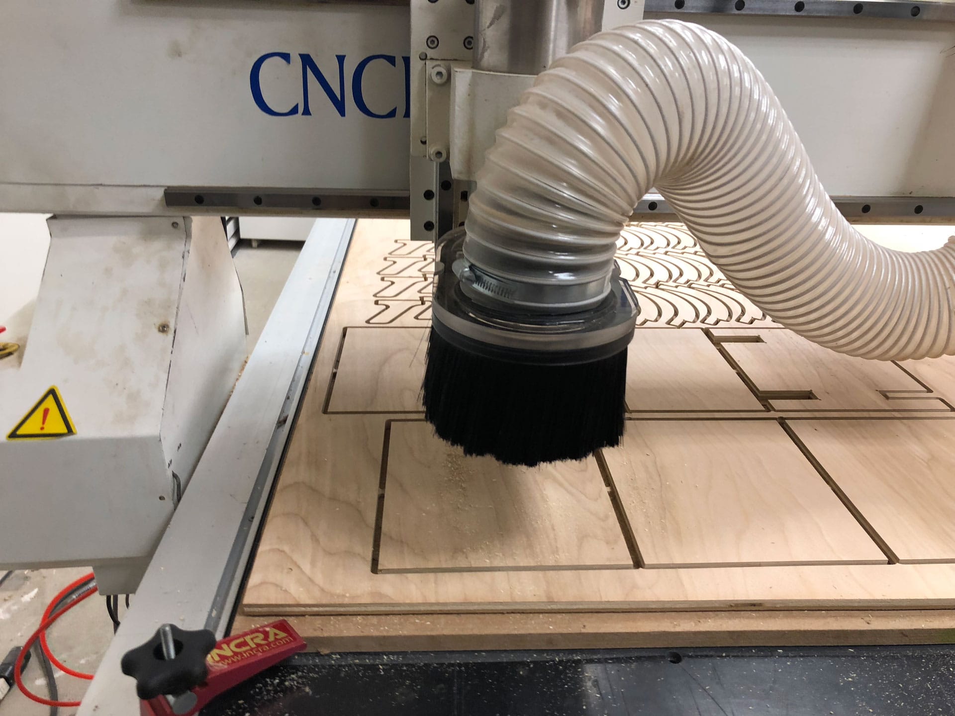
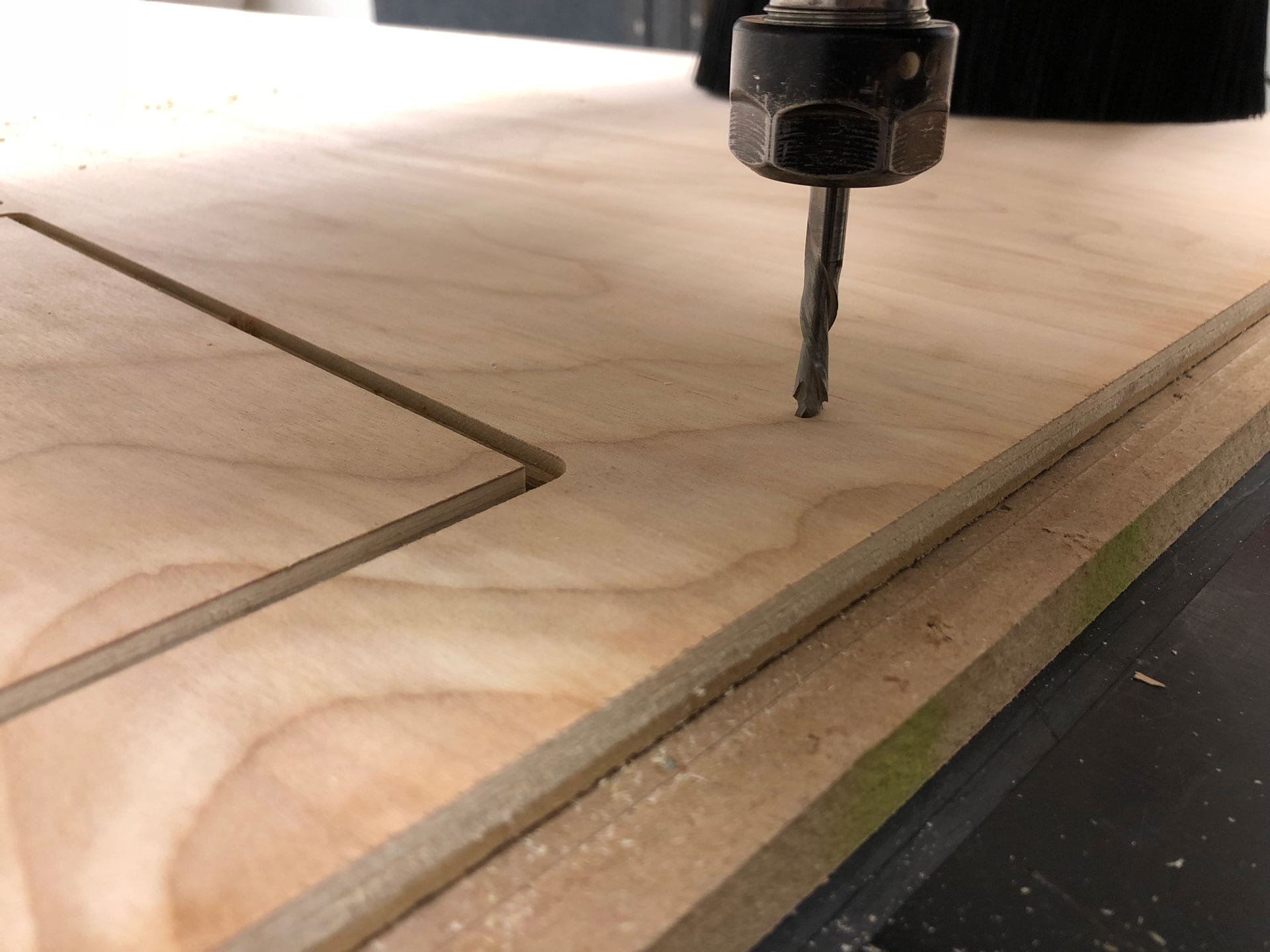
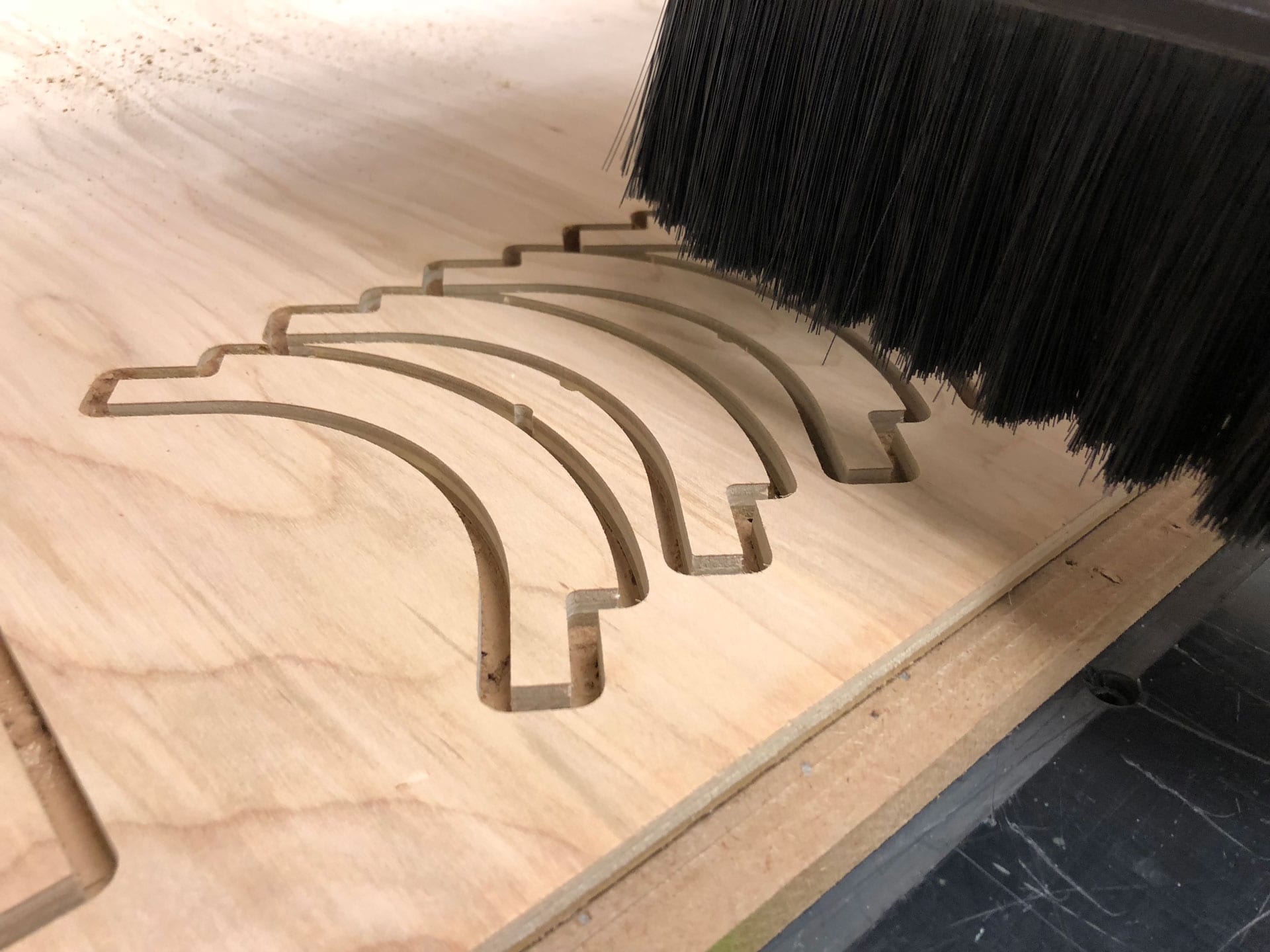
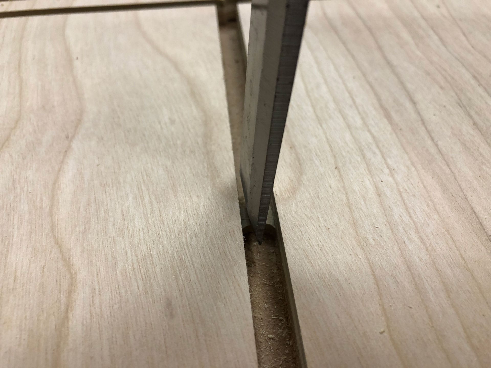
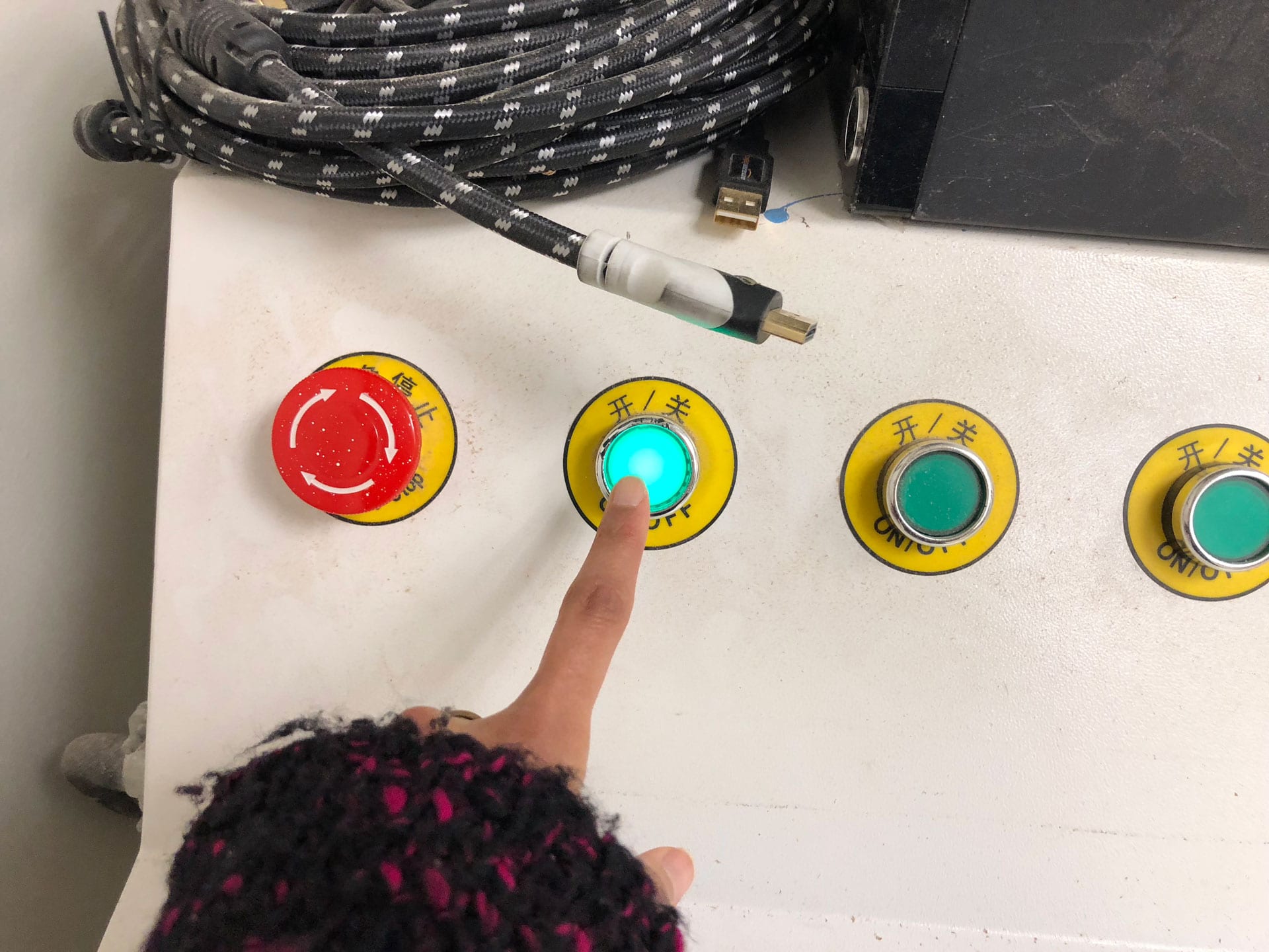
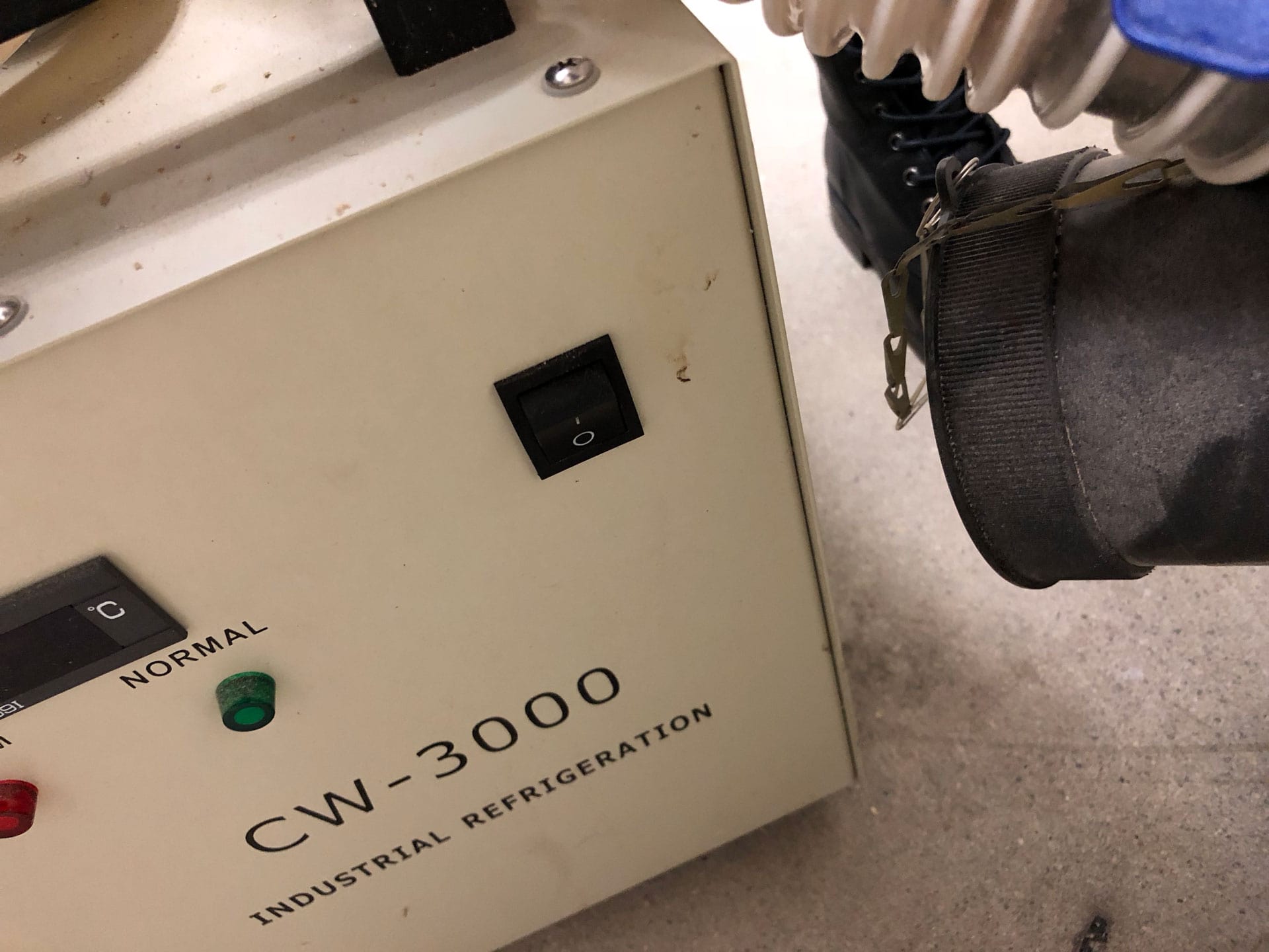
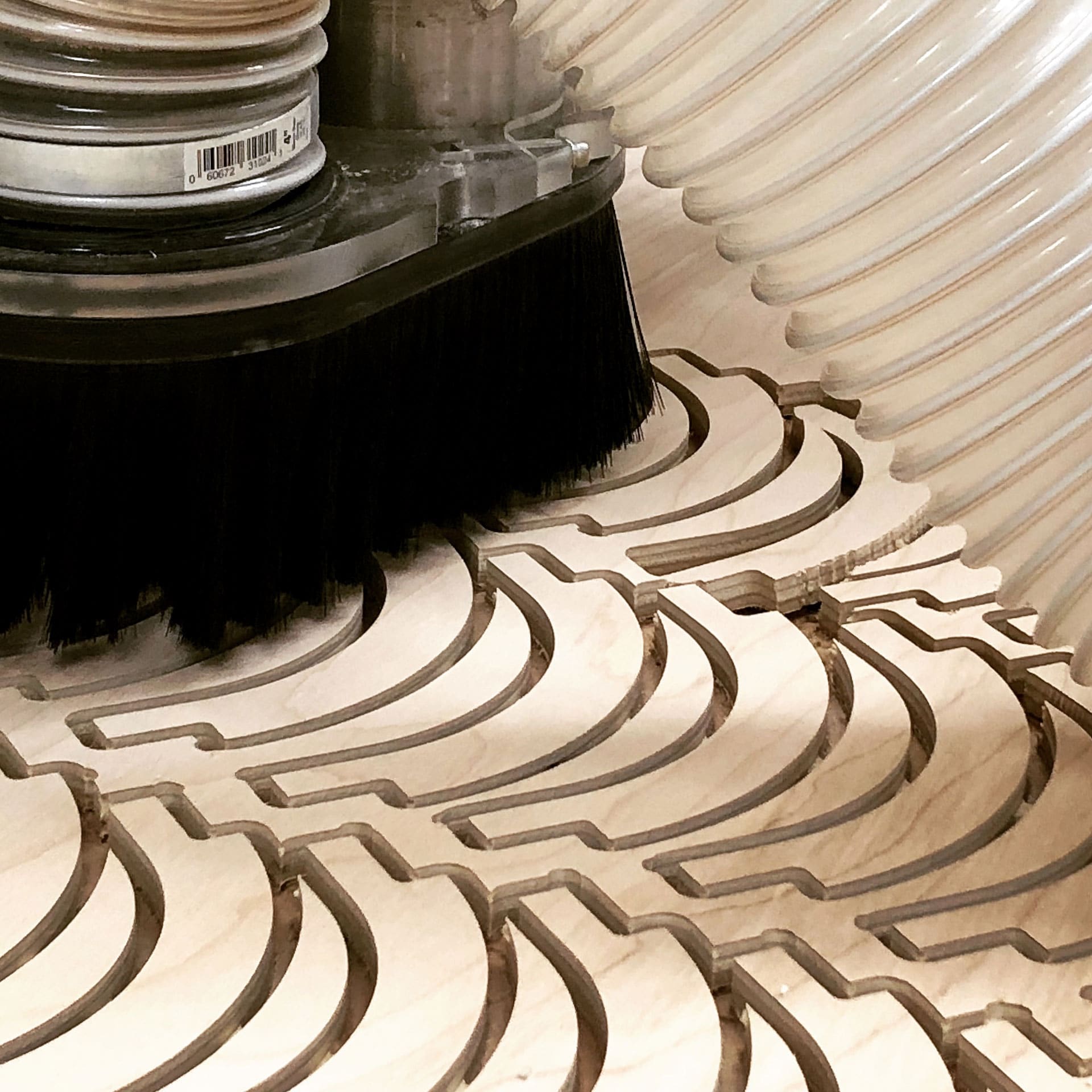
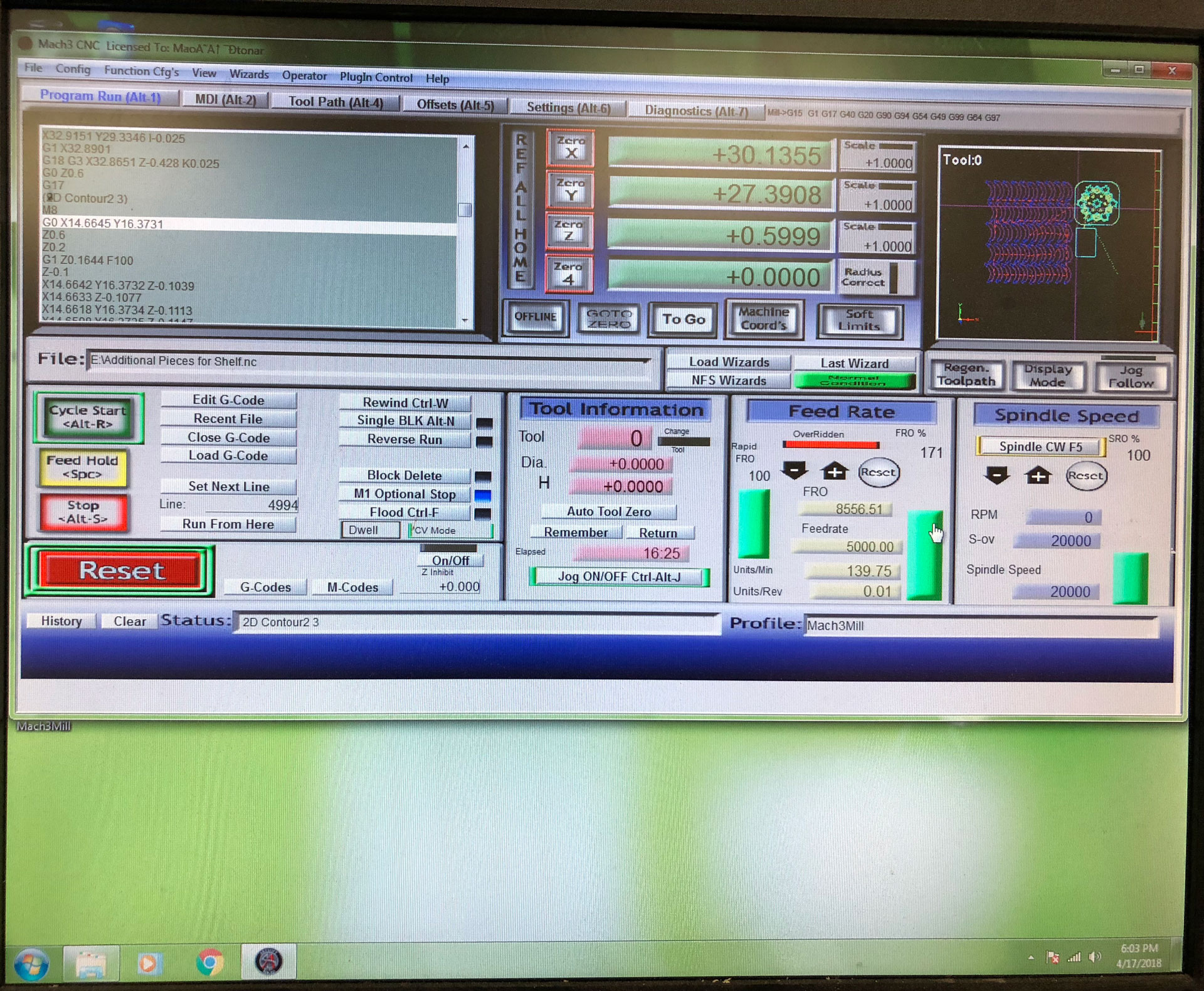
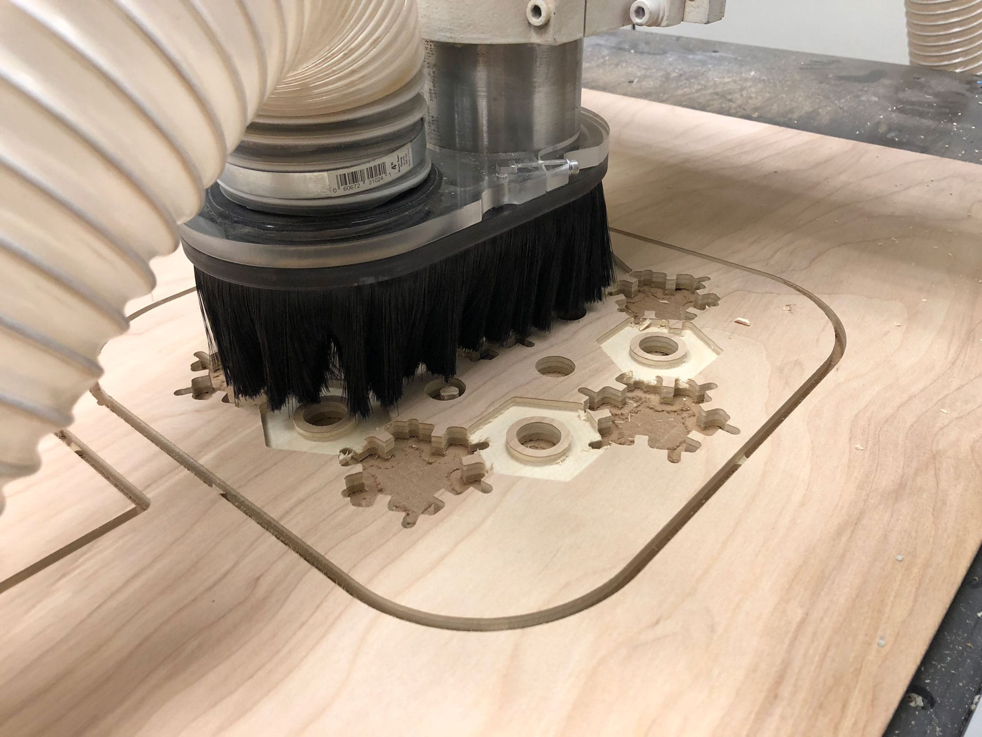
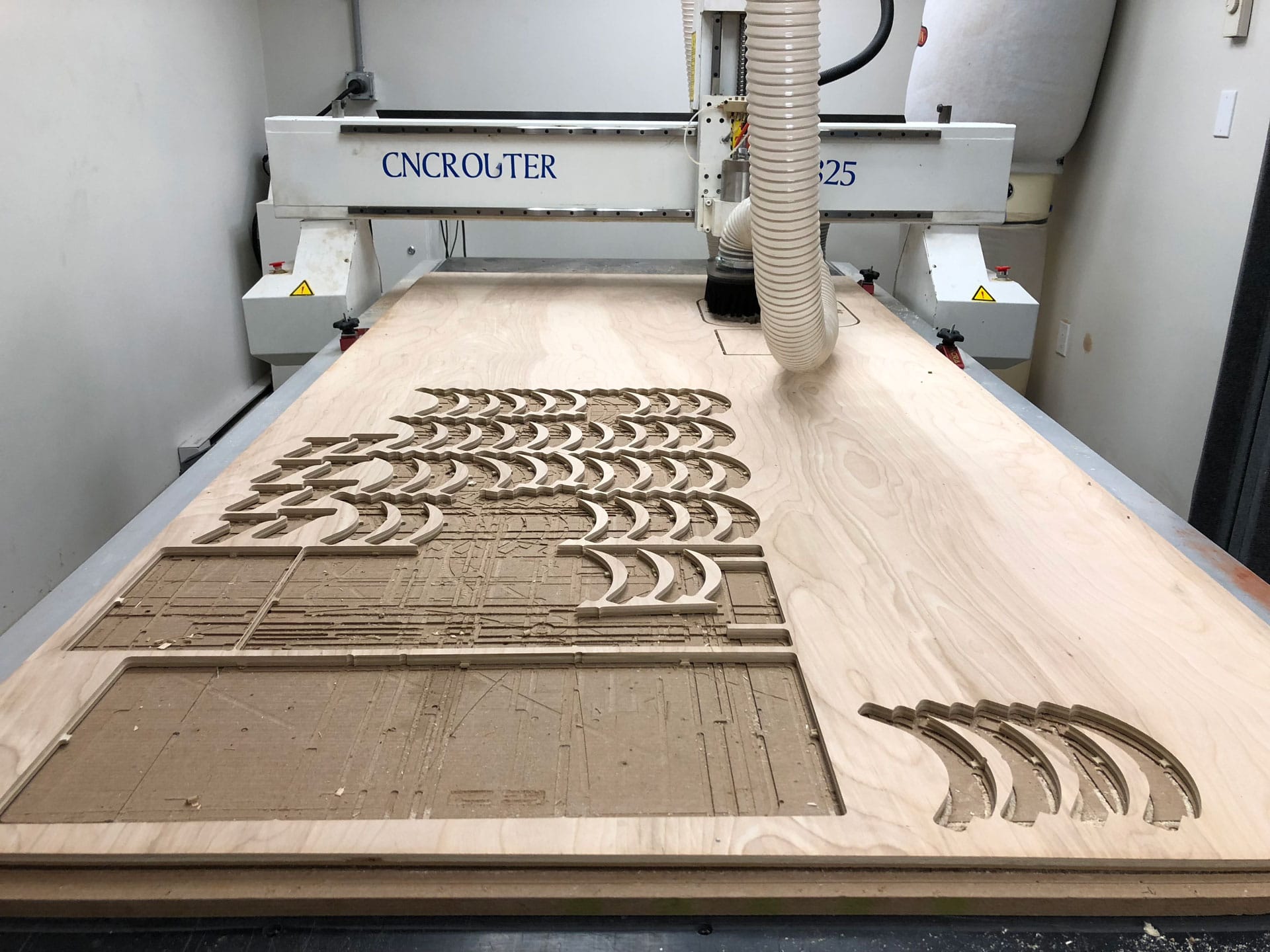
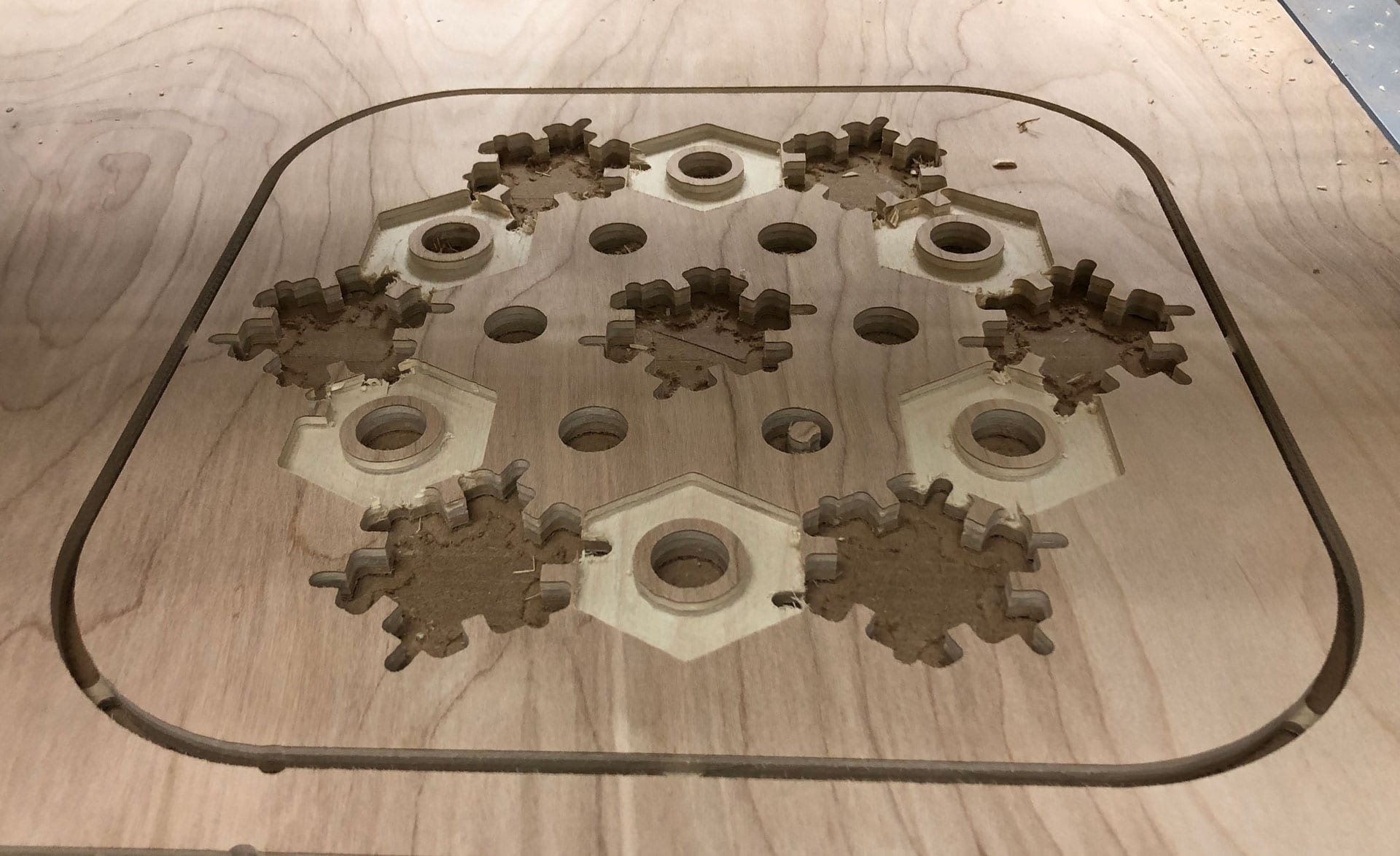
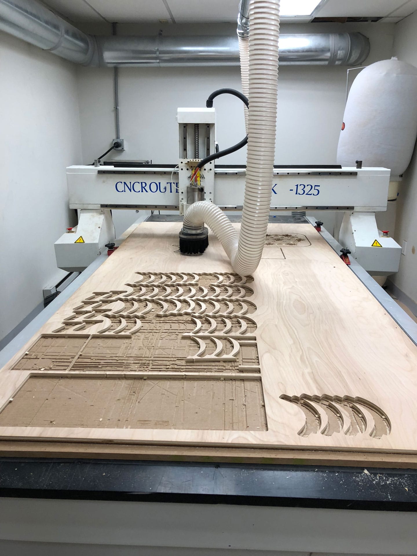
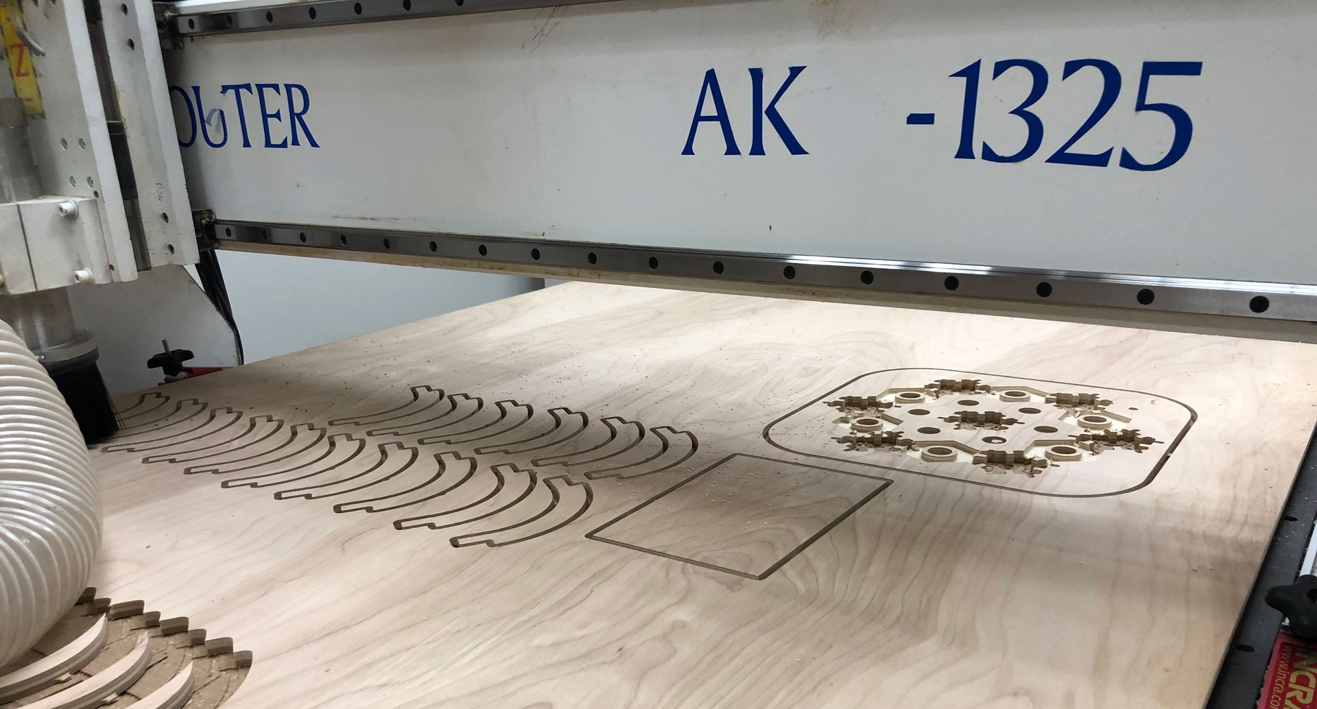
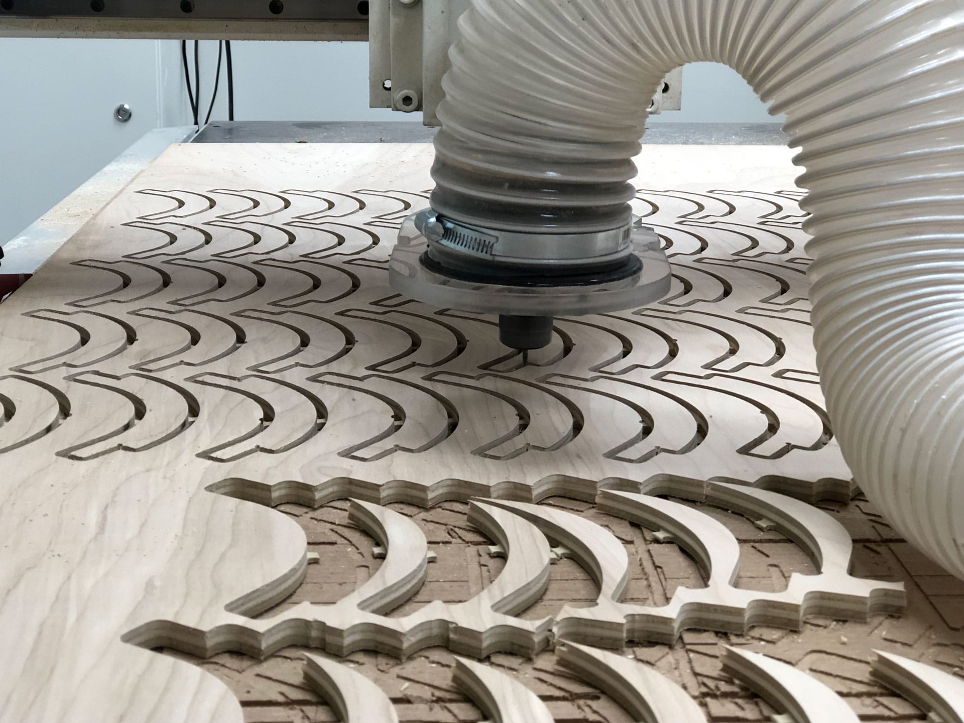
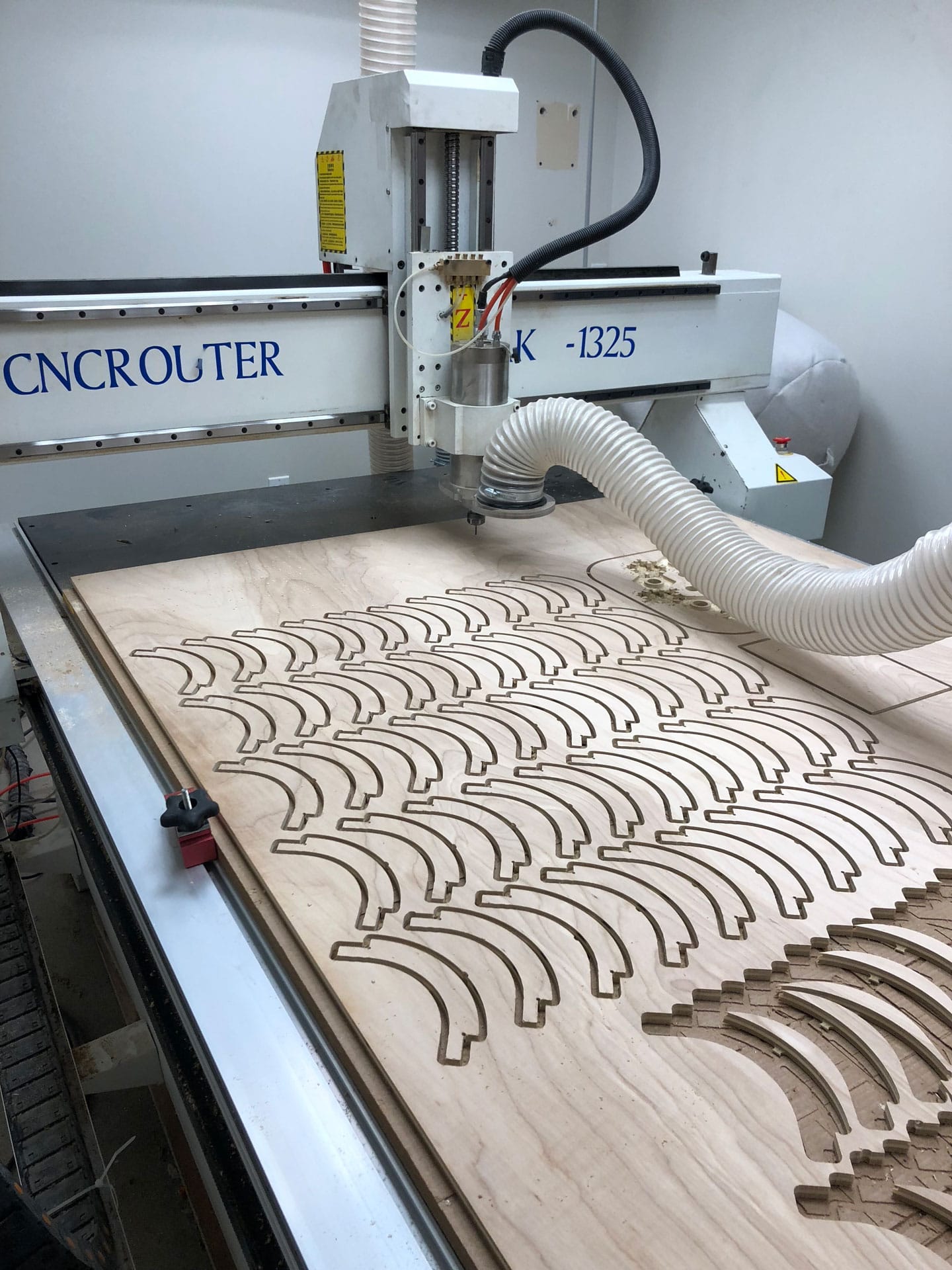
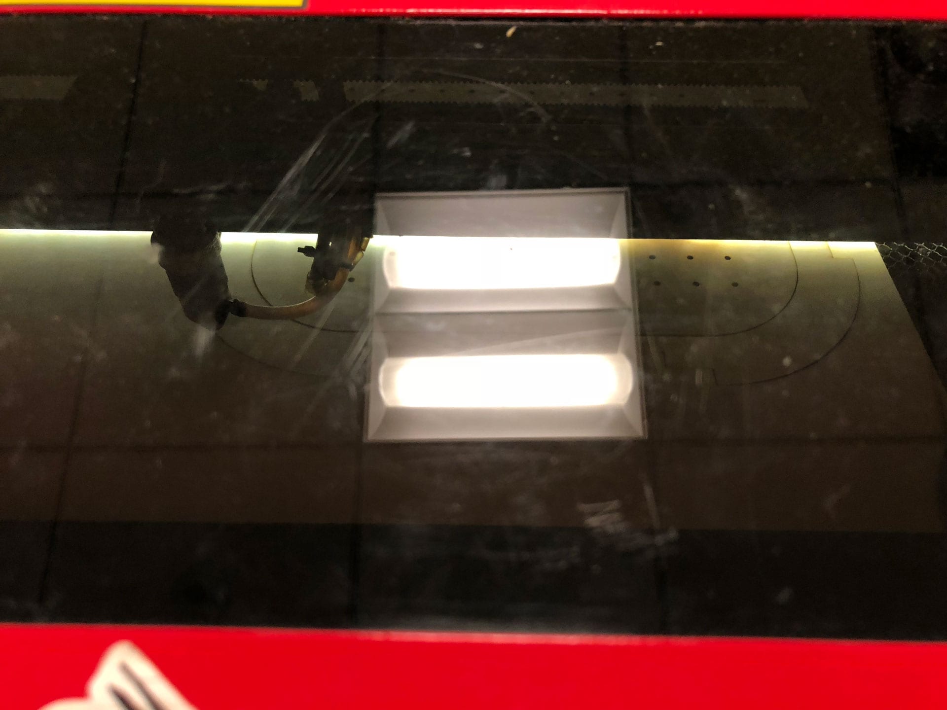
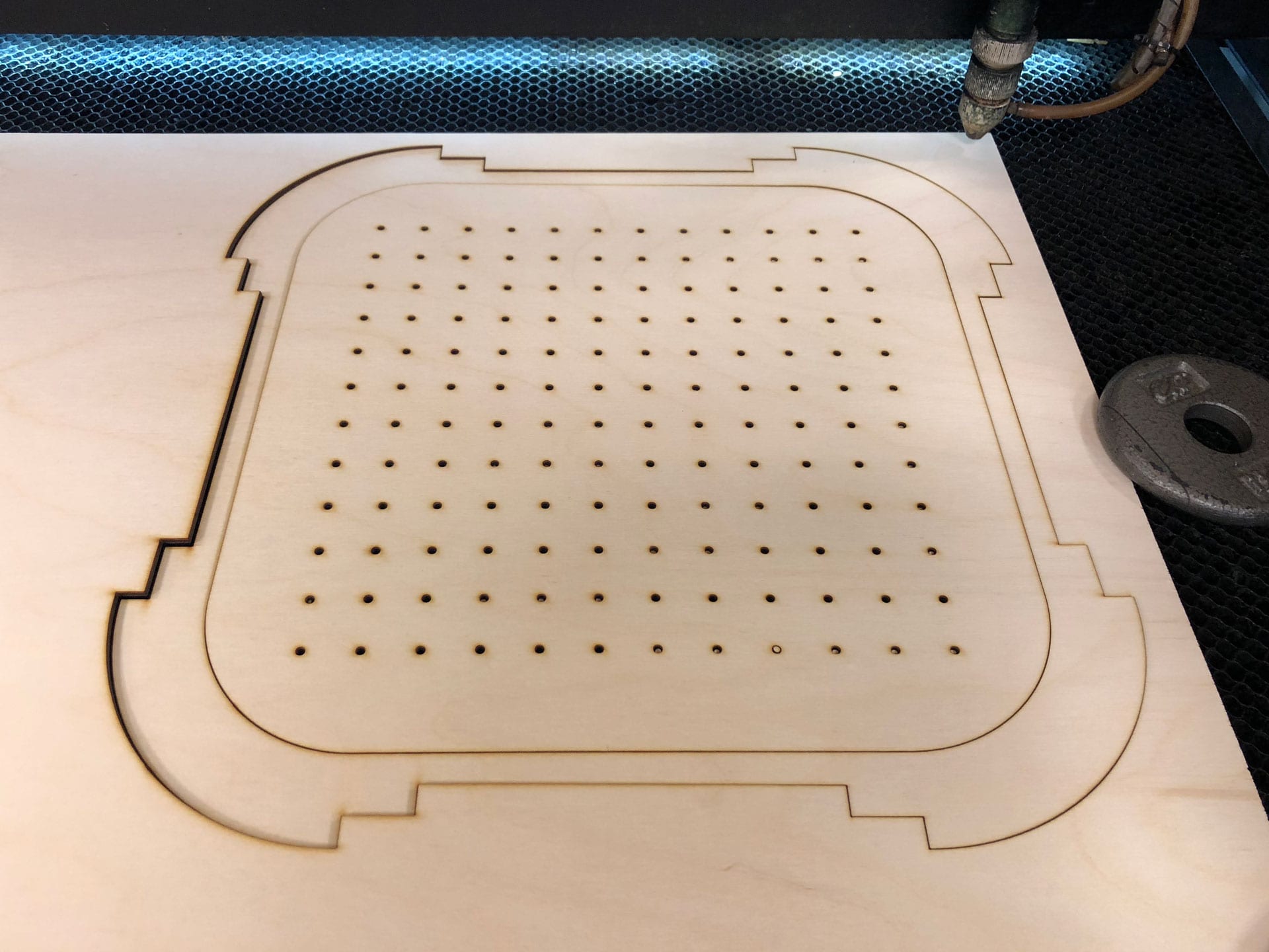
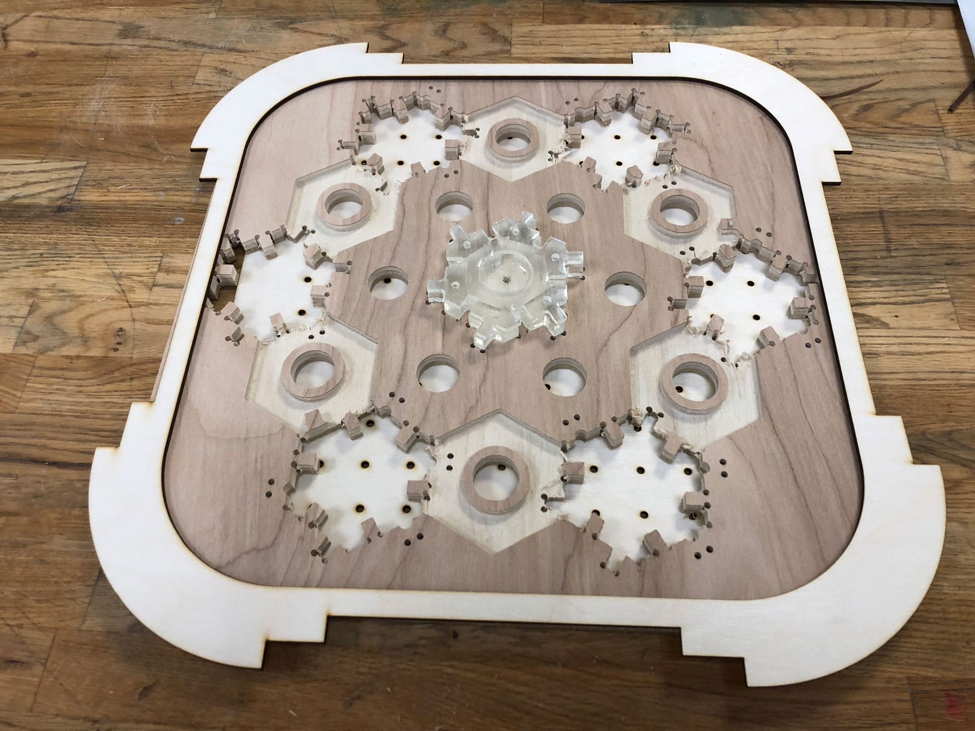
CNC Milling
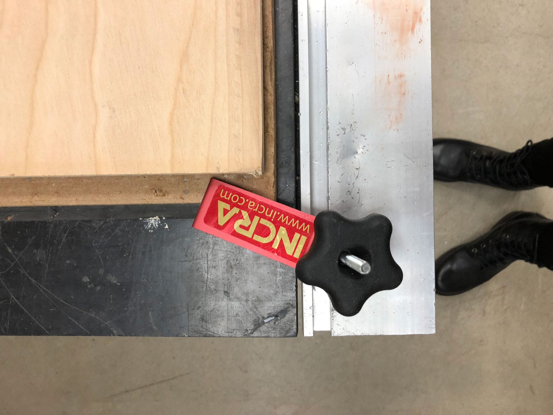
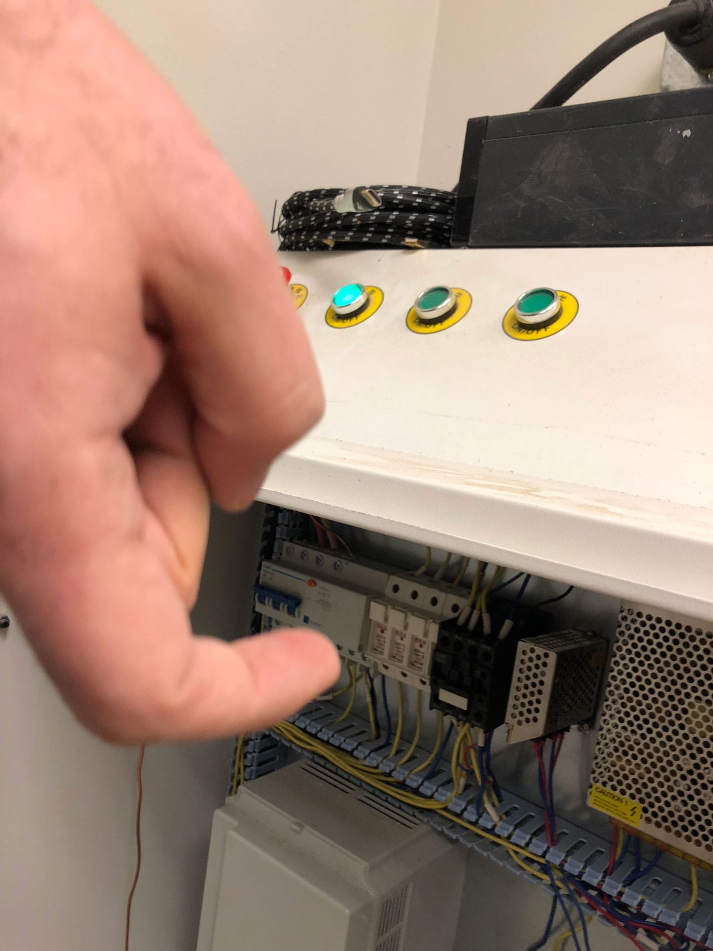
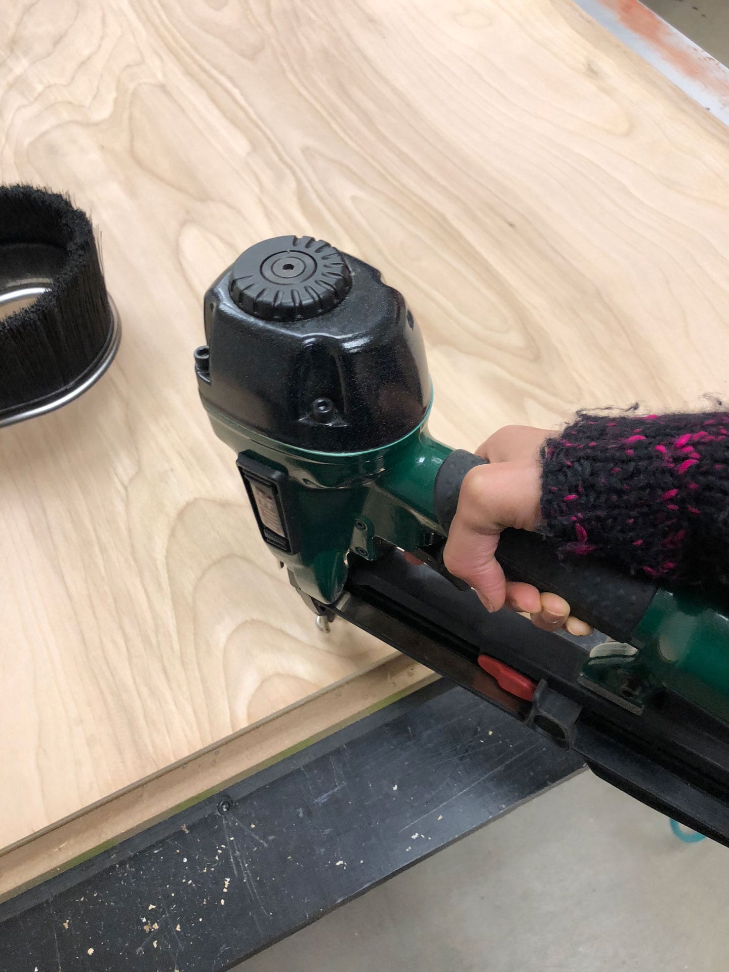
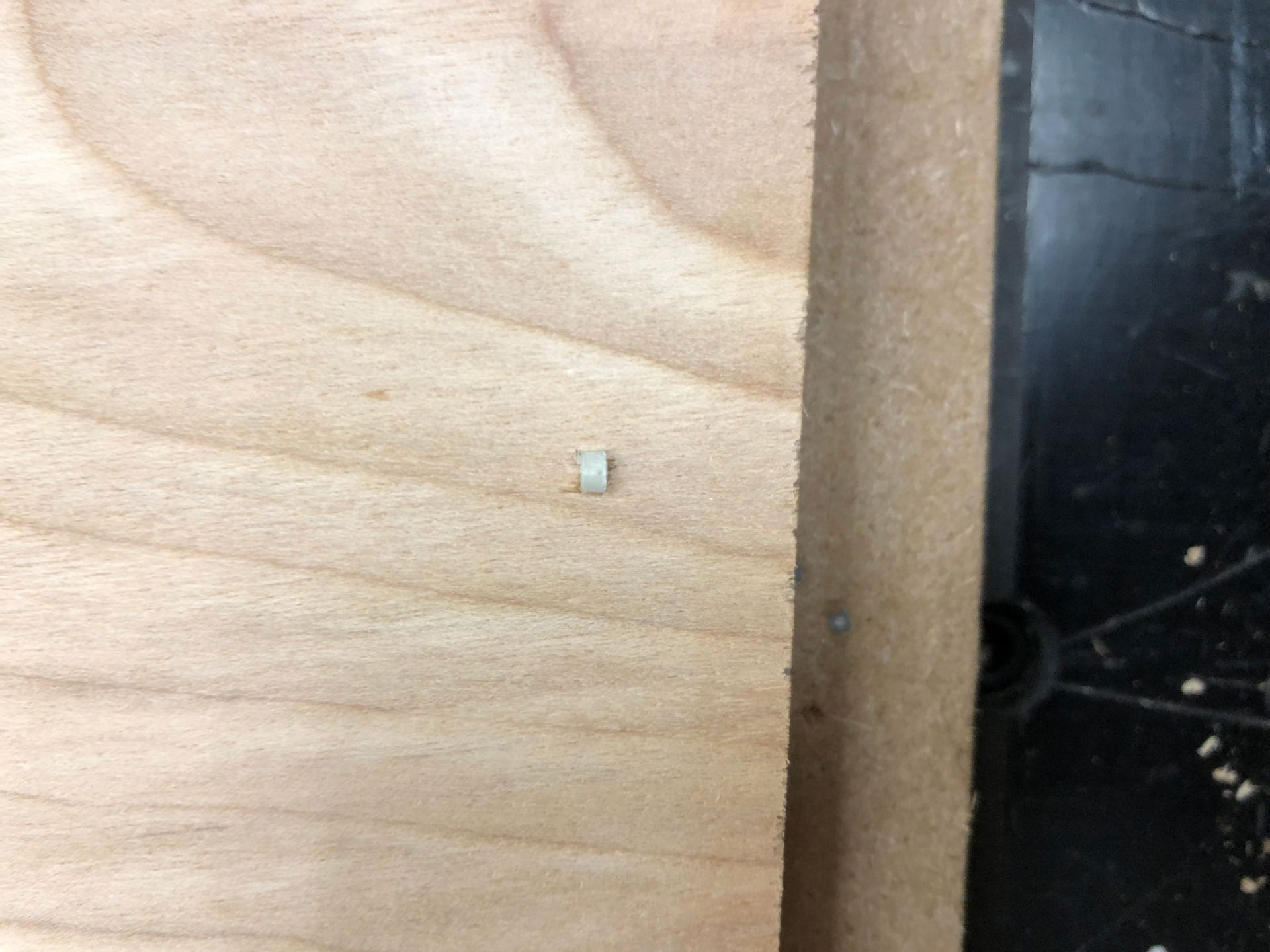
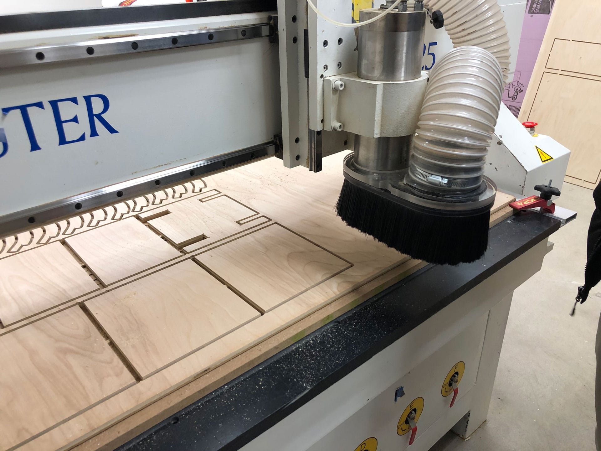
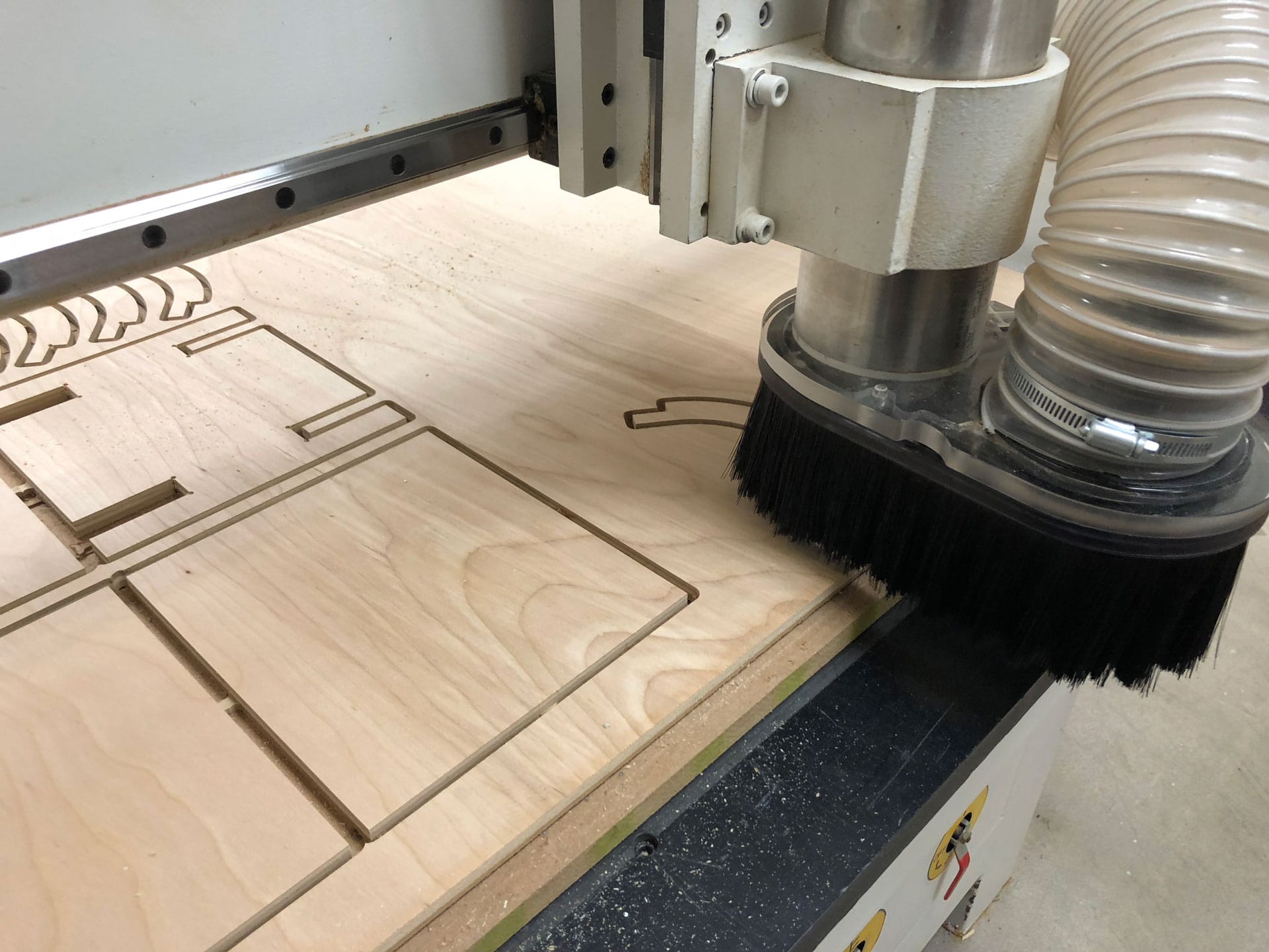
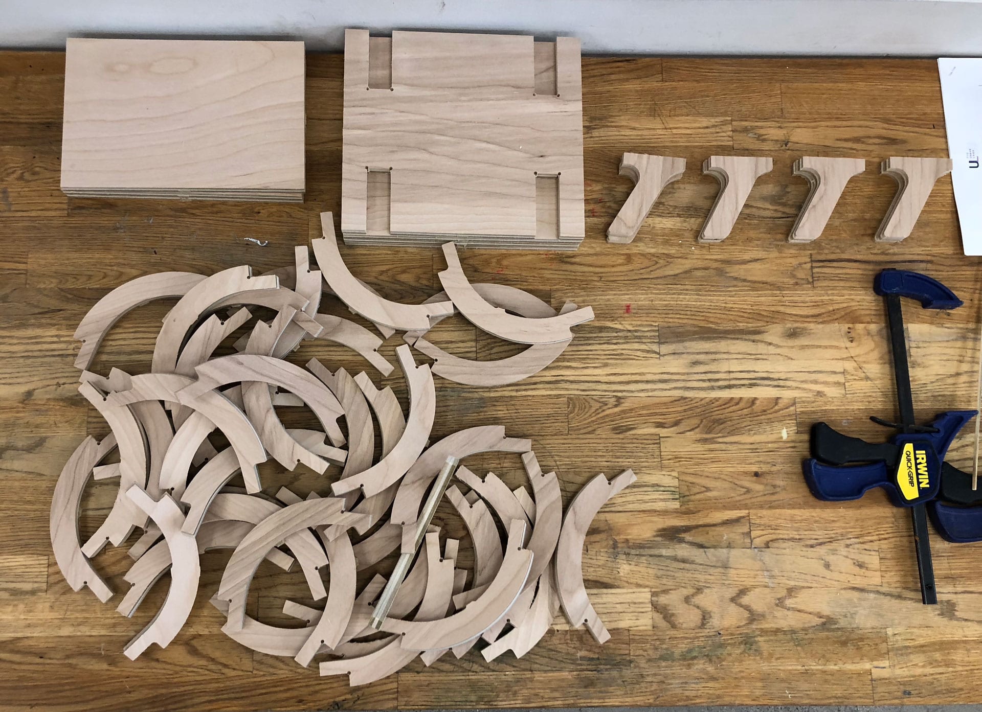
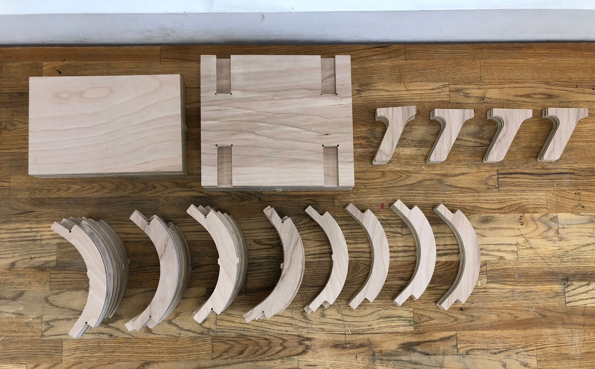
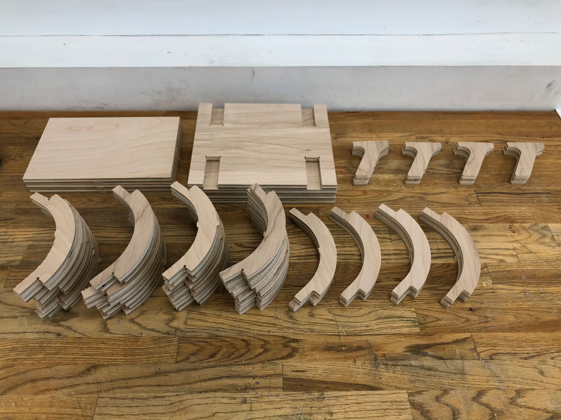
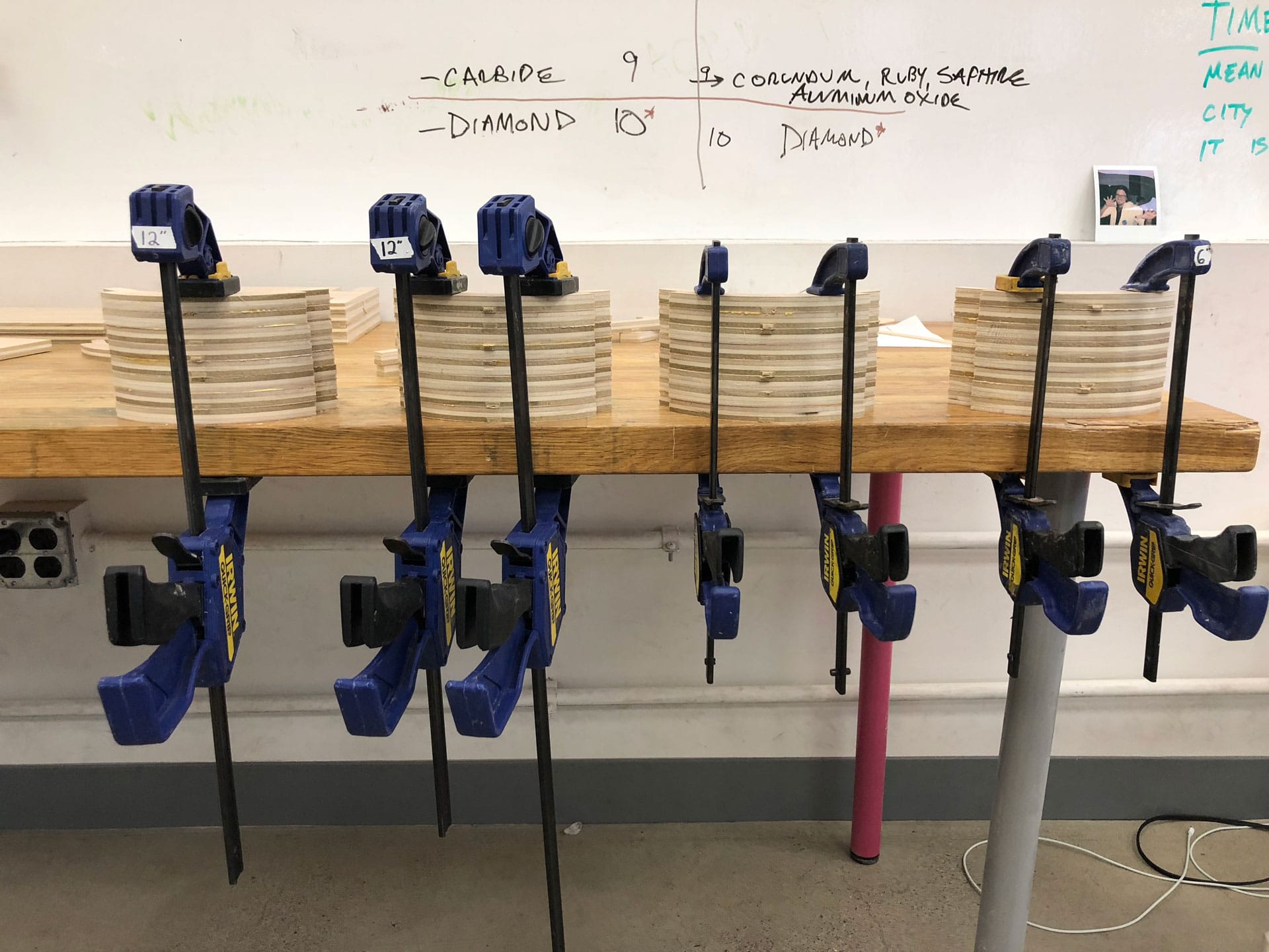
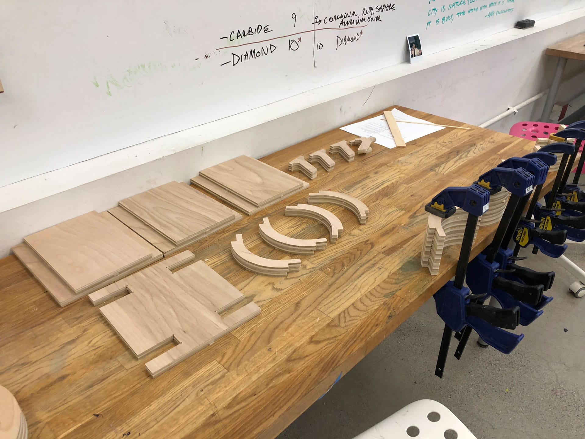
The Milling process took a few hours between prep and actual cutting time. Below is the sequence of my process machining my pieces.
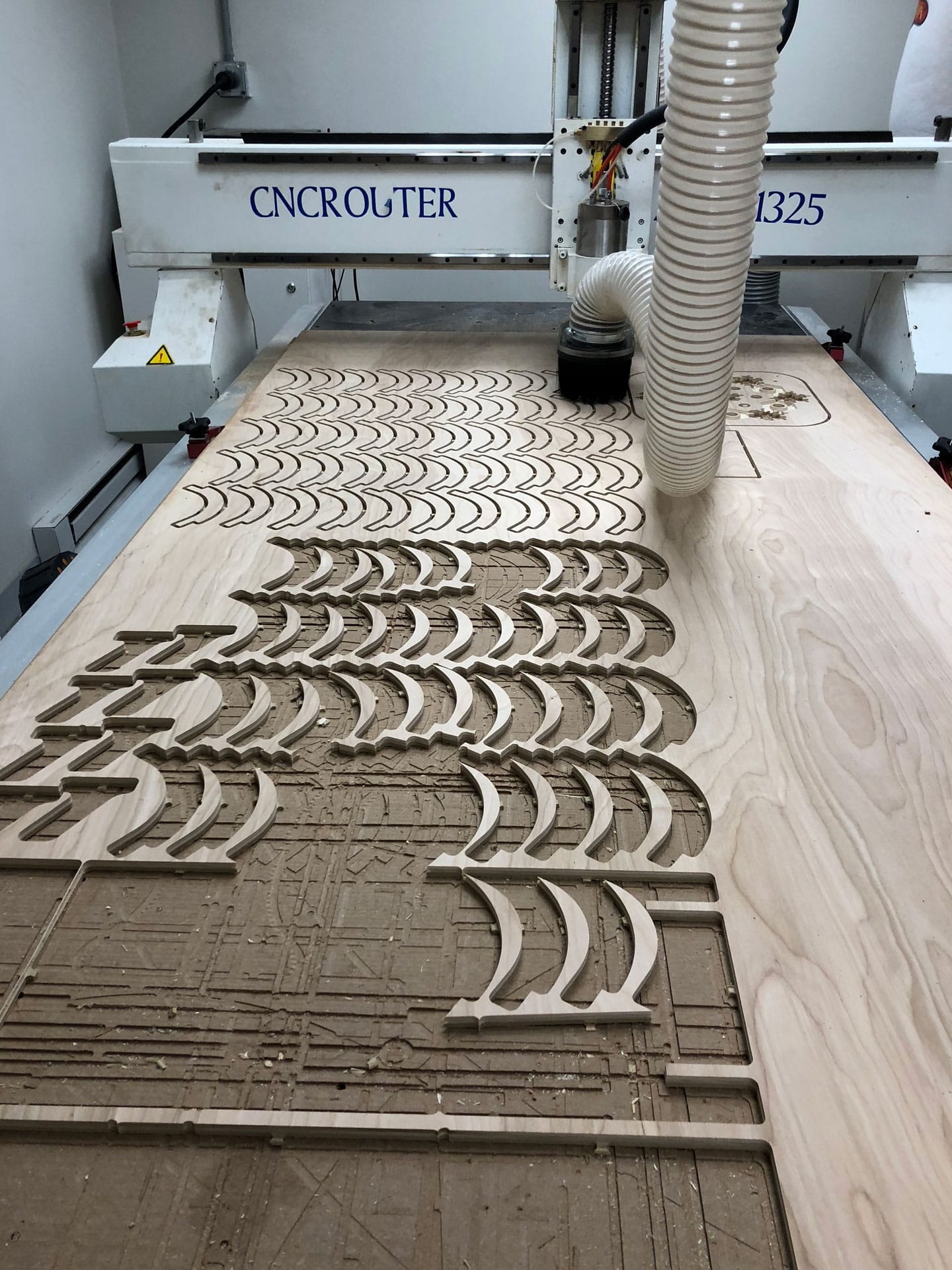
CNC Milling...Part 2
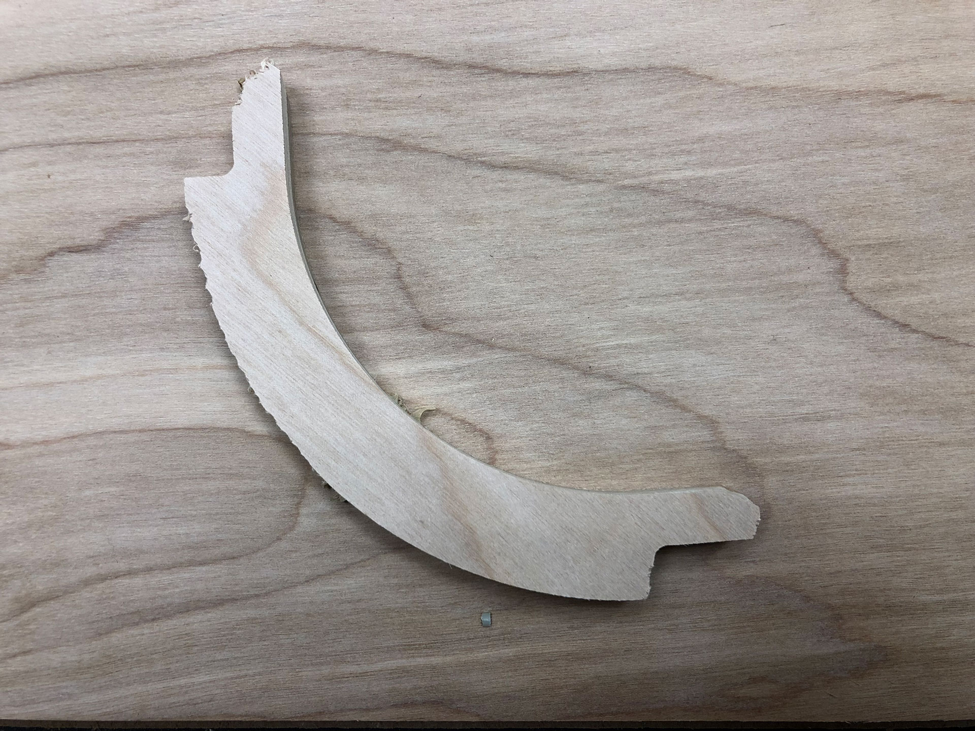
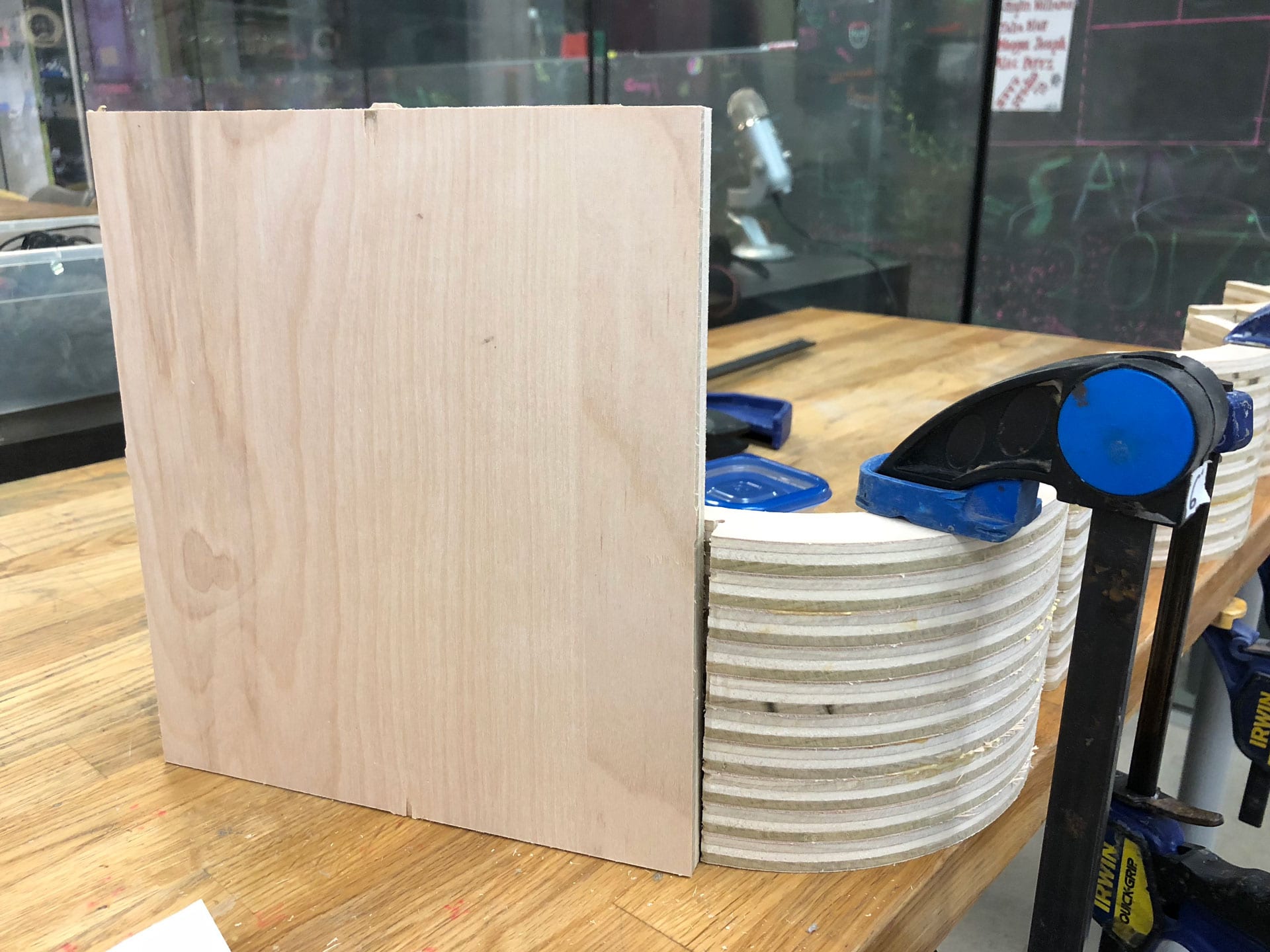
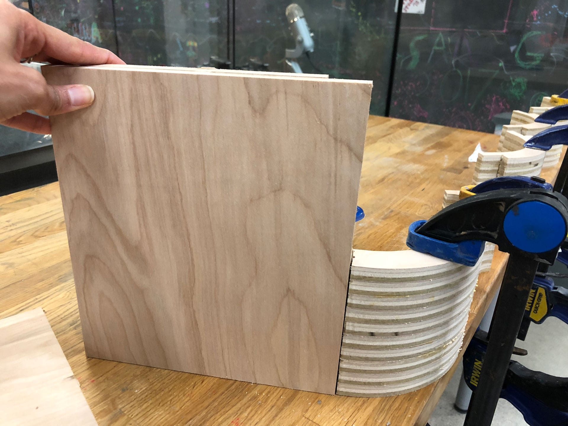
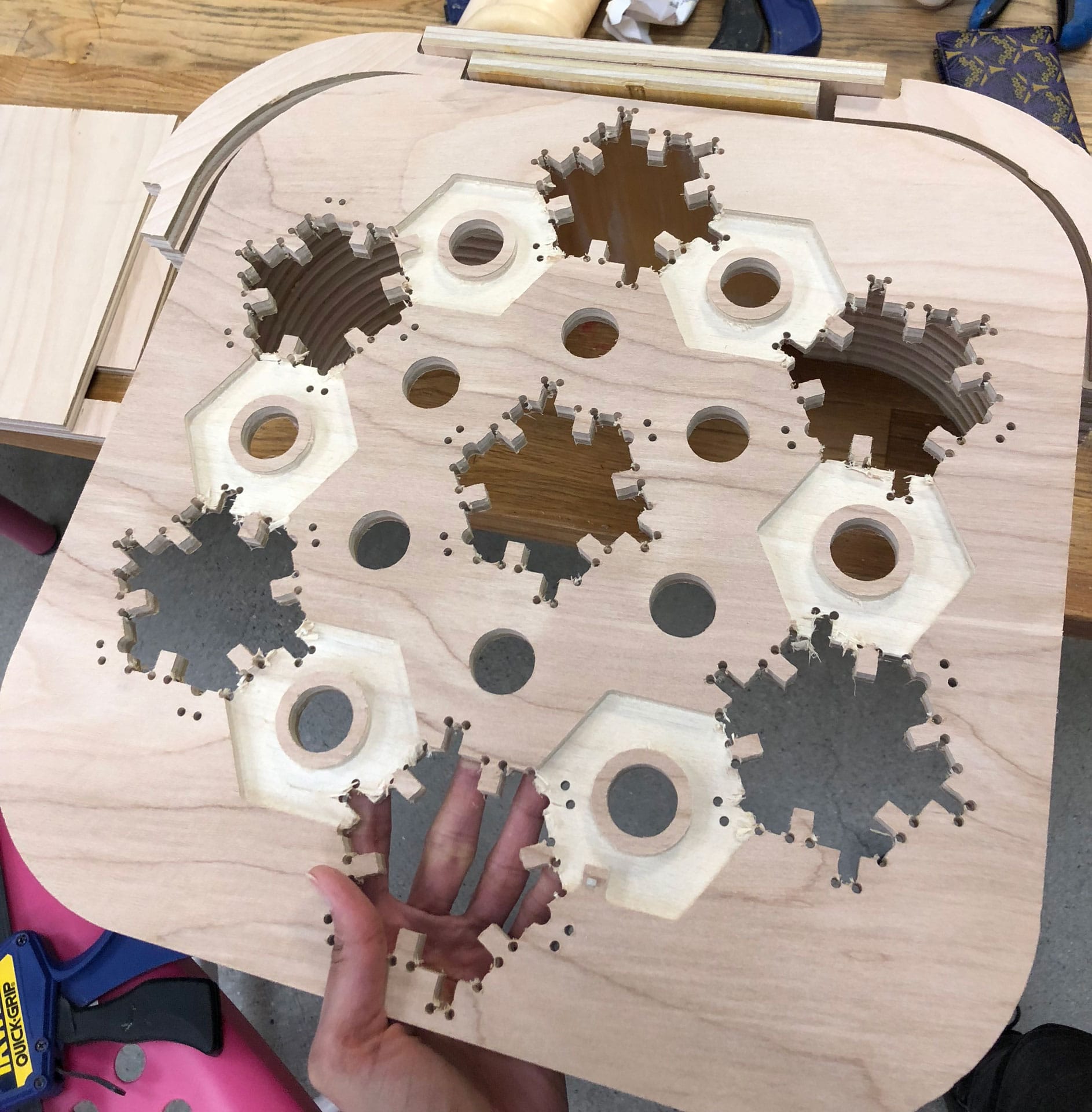
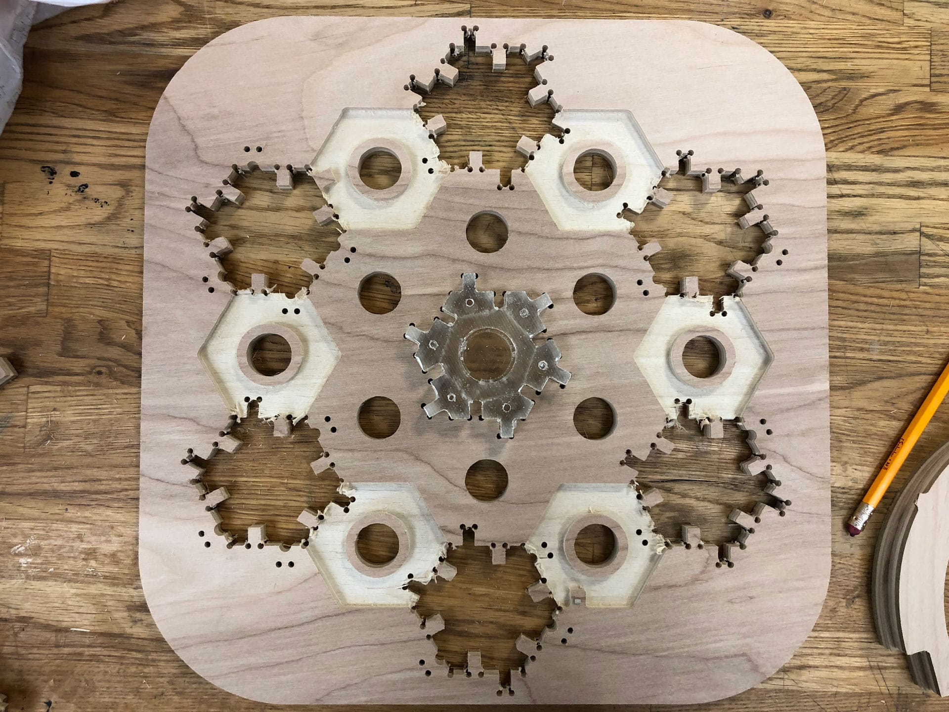
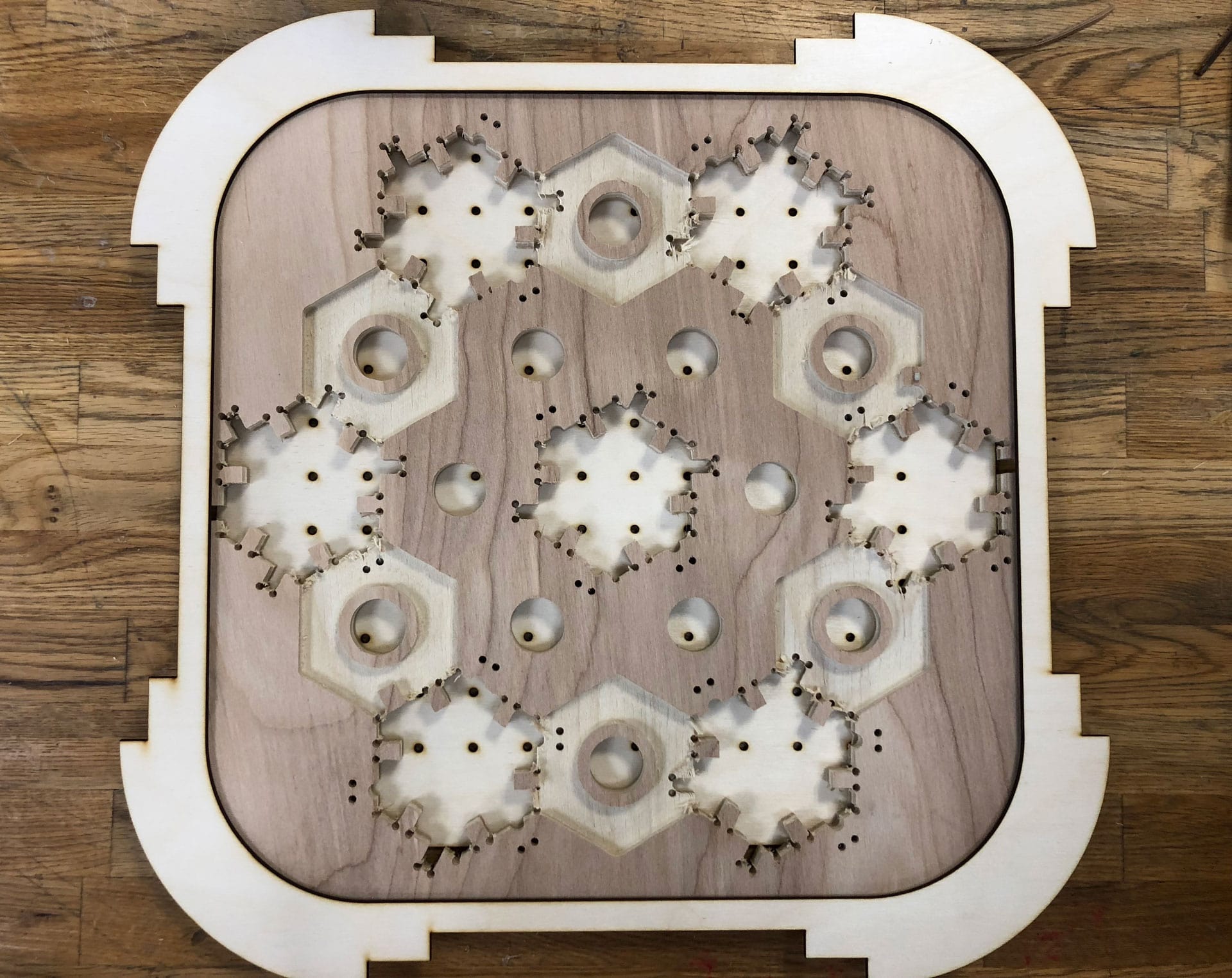
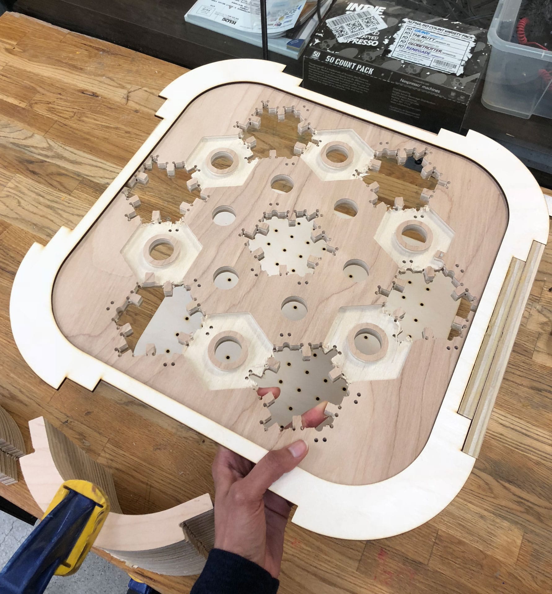
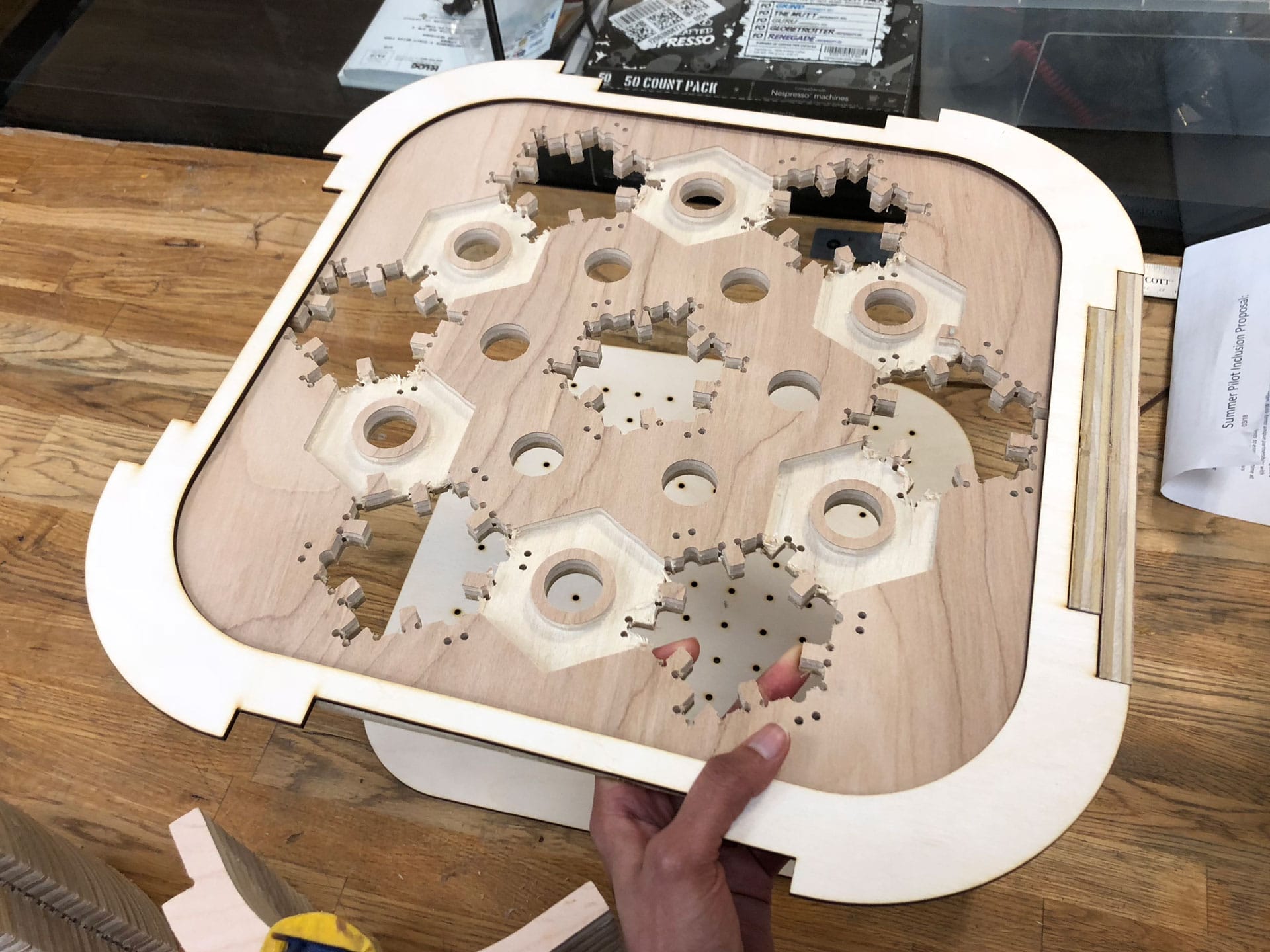
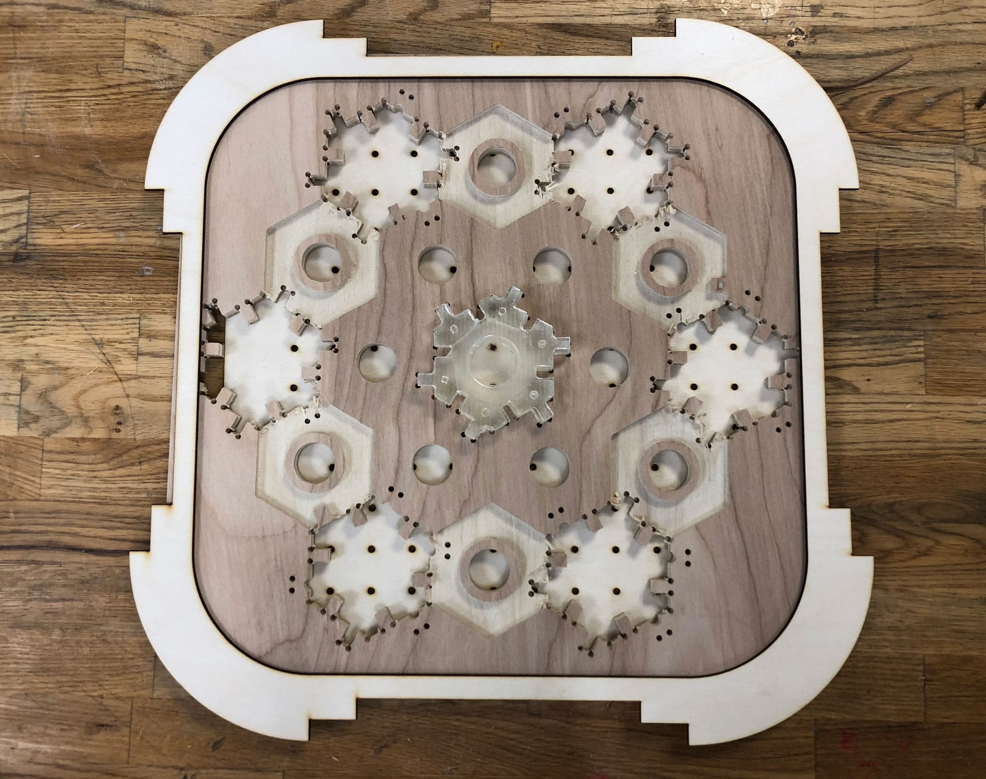
So I discovered soon after milling all my pieces that I needed twice as many cut pieces (oh, sigh!). Back to the milling machine! I recut 50 more corner pieces, a few extra to be on the safe side. I also did a test cut of the shelf facade.
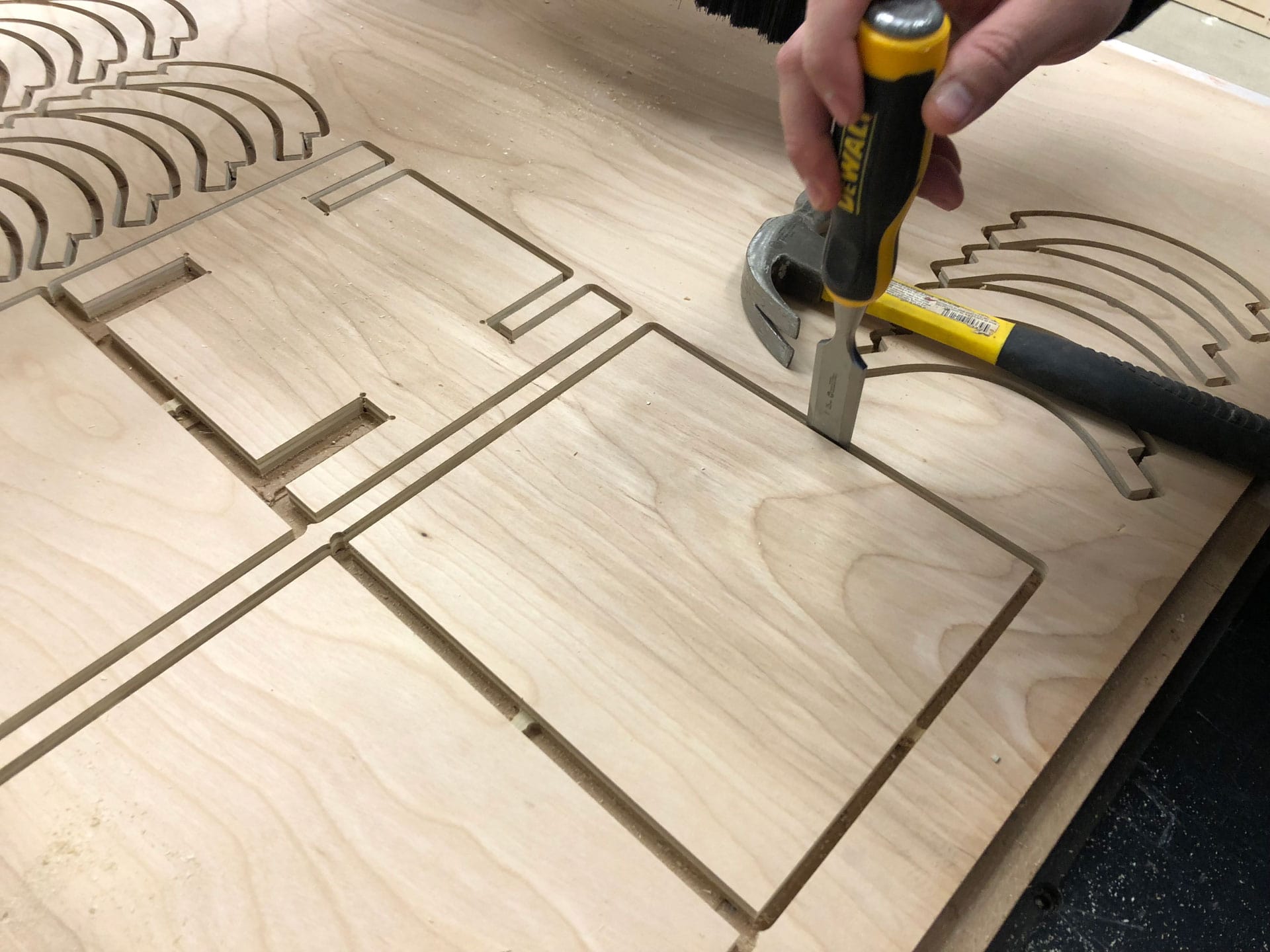
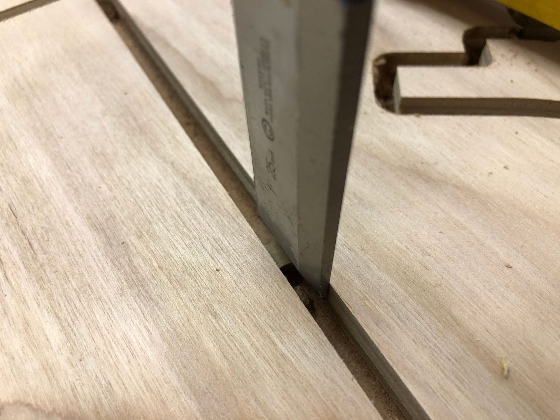
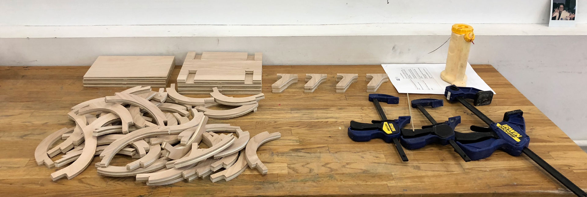
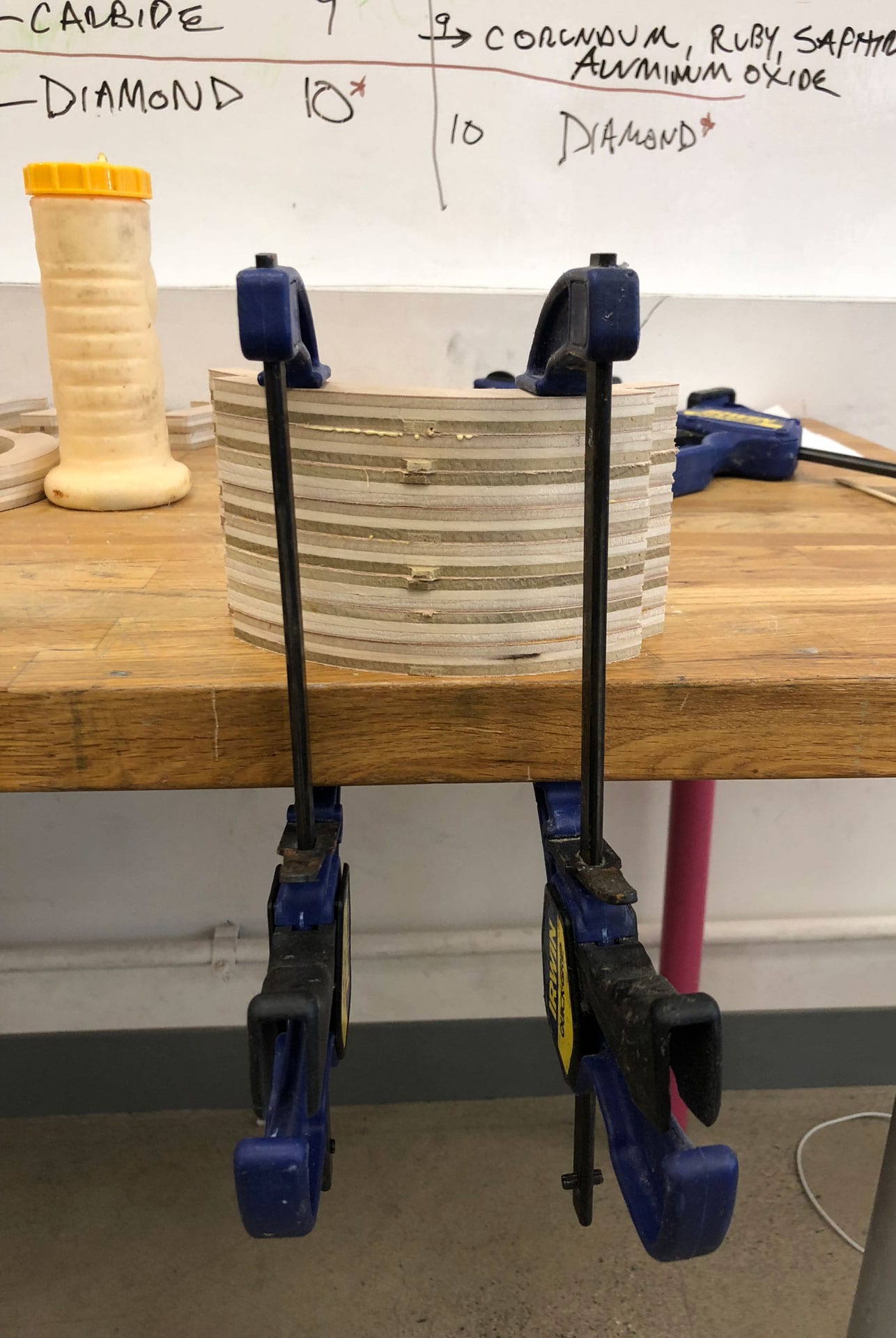
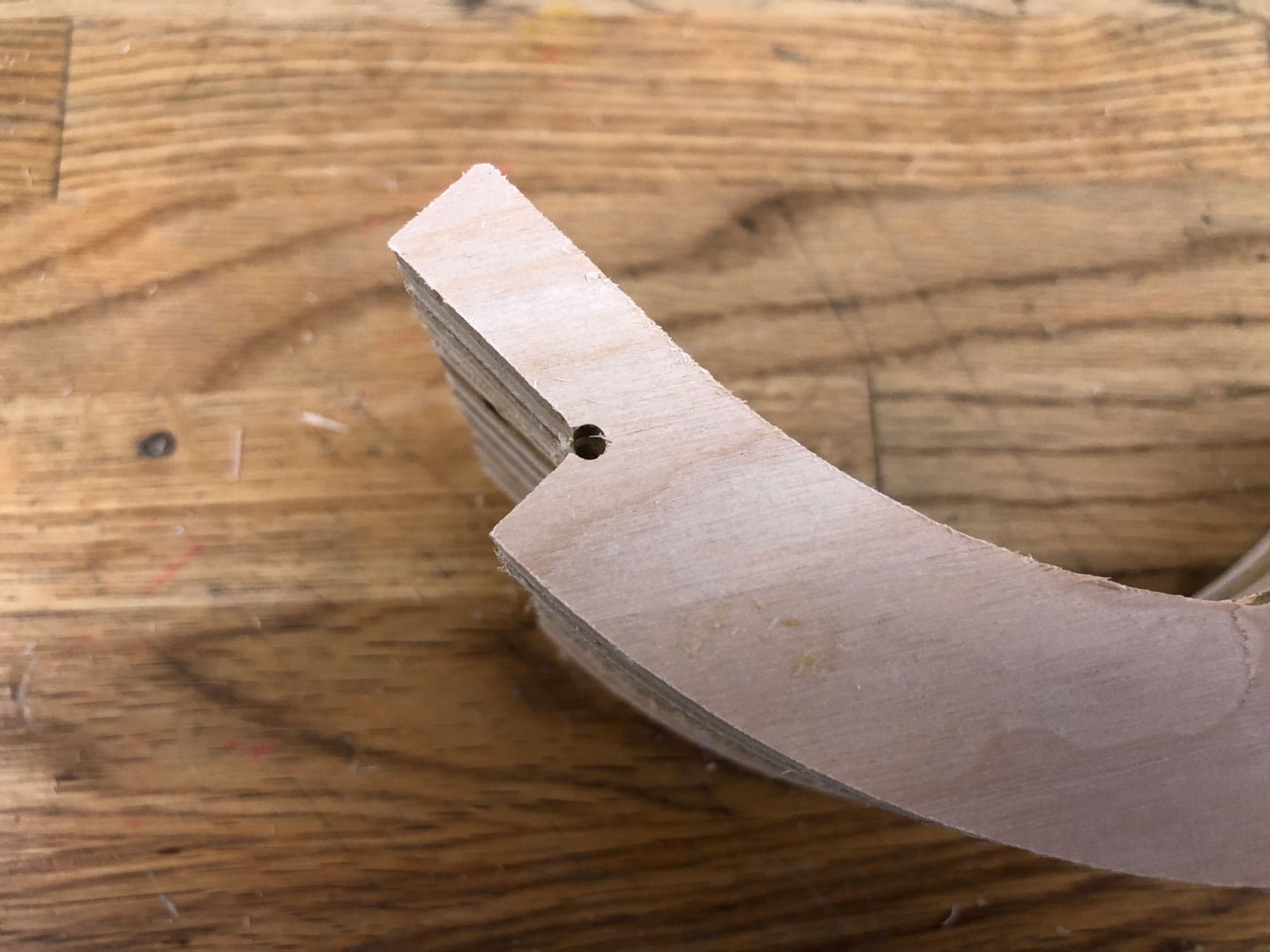
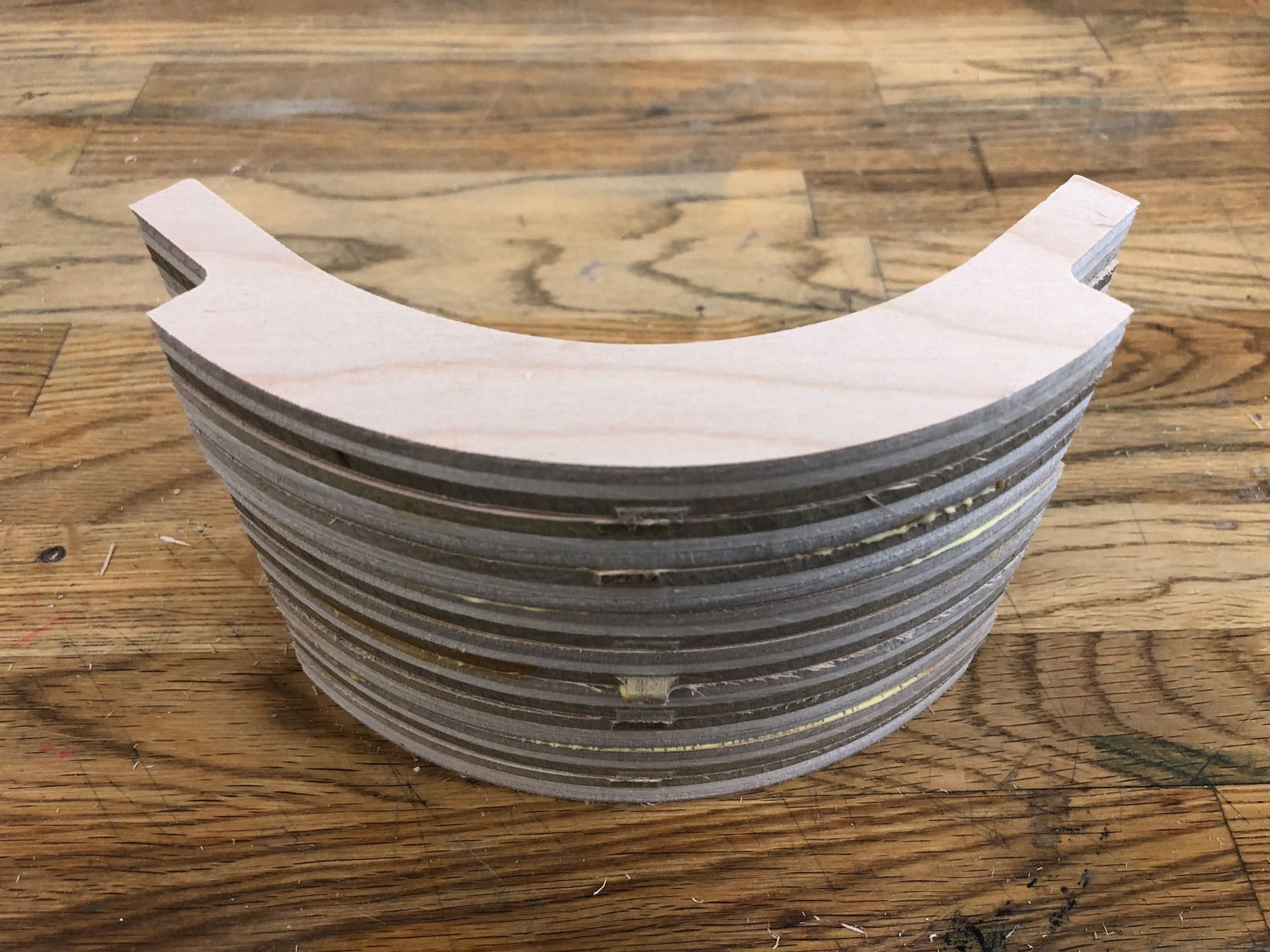
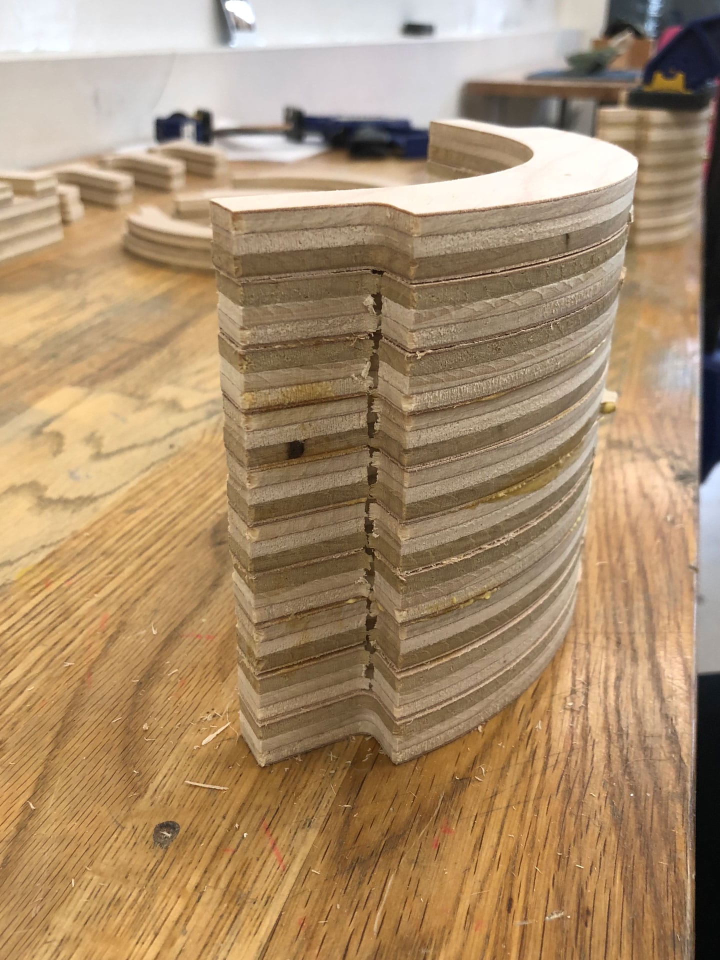
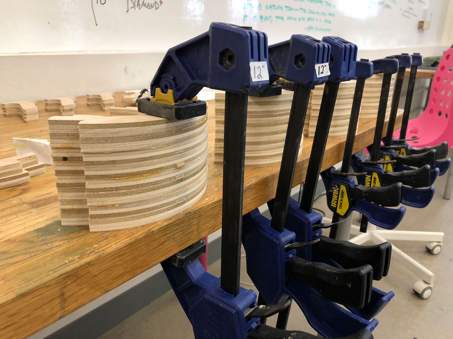
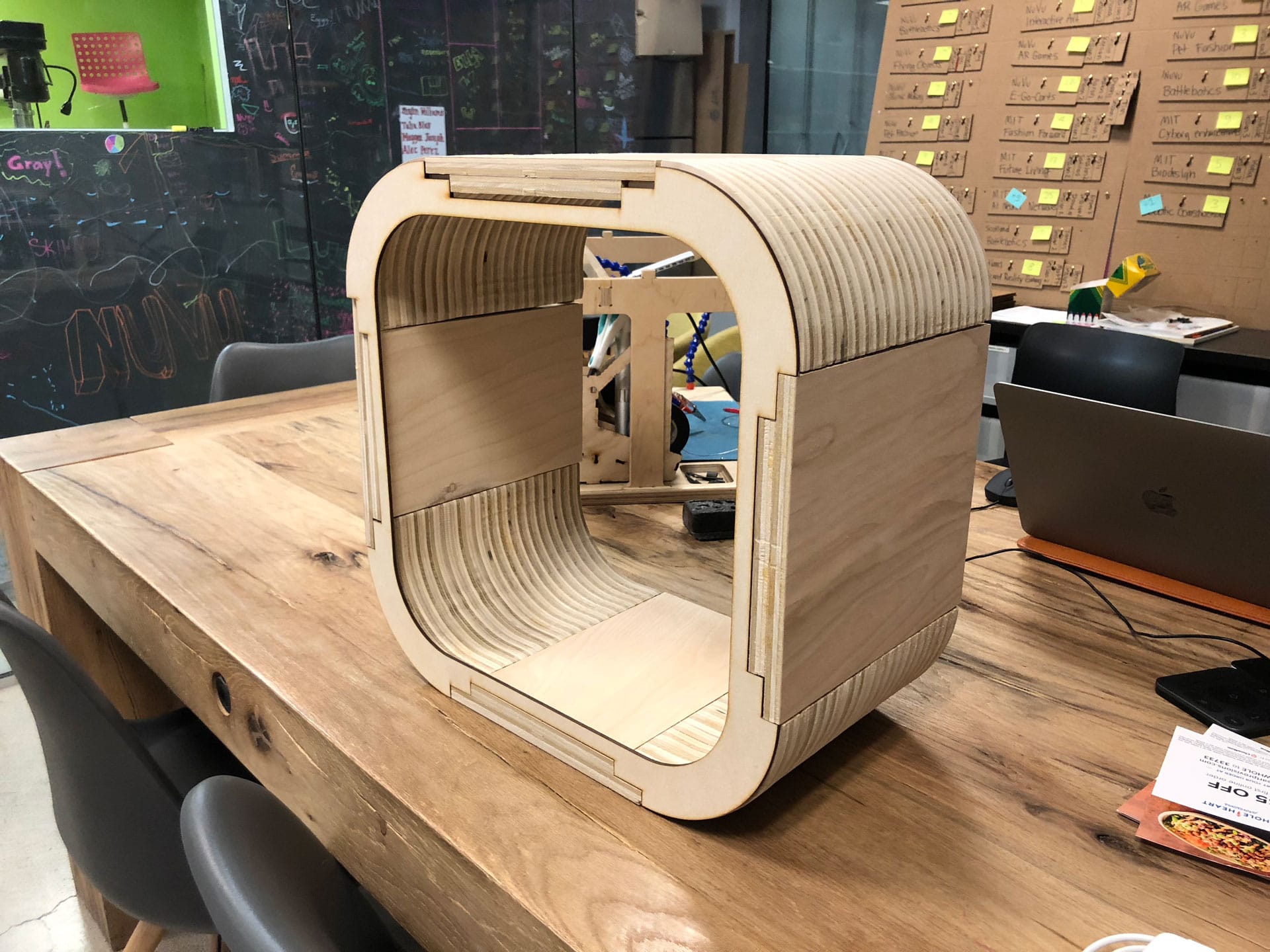
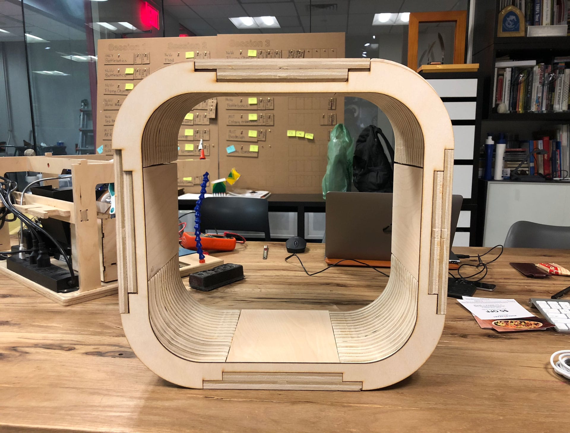
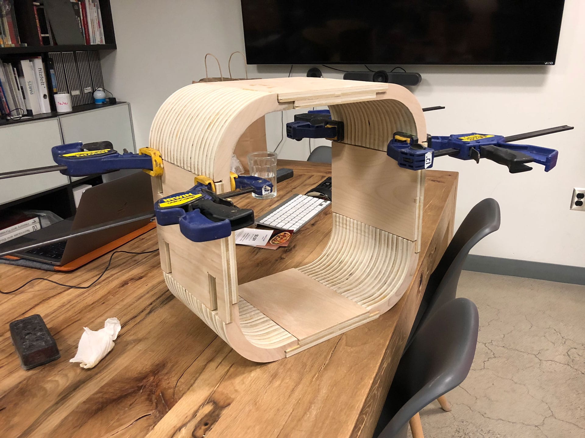
Assembling
So I discovered soon after milling all my pieces that I needed twice as many cut pieces (oh, sigh!). Back to the milling machine! I recut 50 more corner pieces, a few extra to be on the safe side. I also did a test cut of the shelf facade.
Download the Fusion 360 3D model of the interactive shelf.