Exercise 10: Input Devices
Input Devices
- Group Project: Measure the analog levels and digital signals in an input device.
- Individual Project: Measure something: add a sensor to a microcontroller board that you have designed and read it.
My Process (Creating an Input and Output Board)
:: April 8, 2018 ::
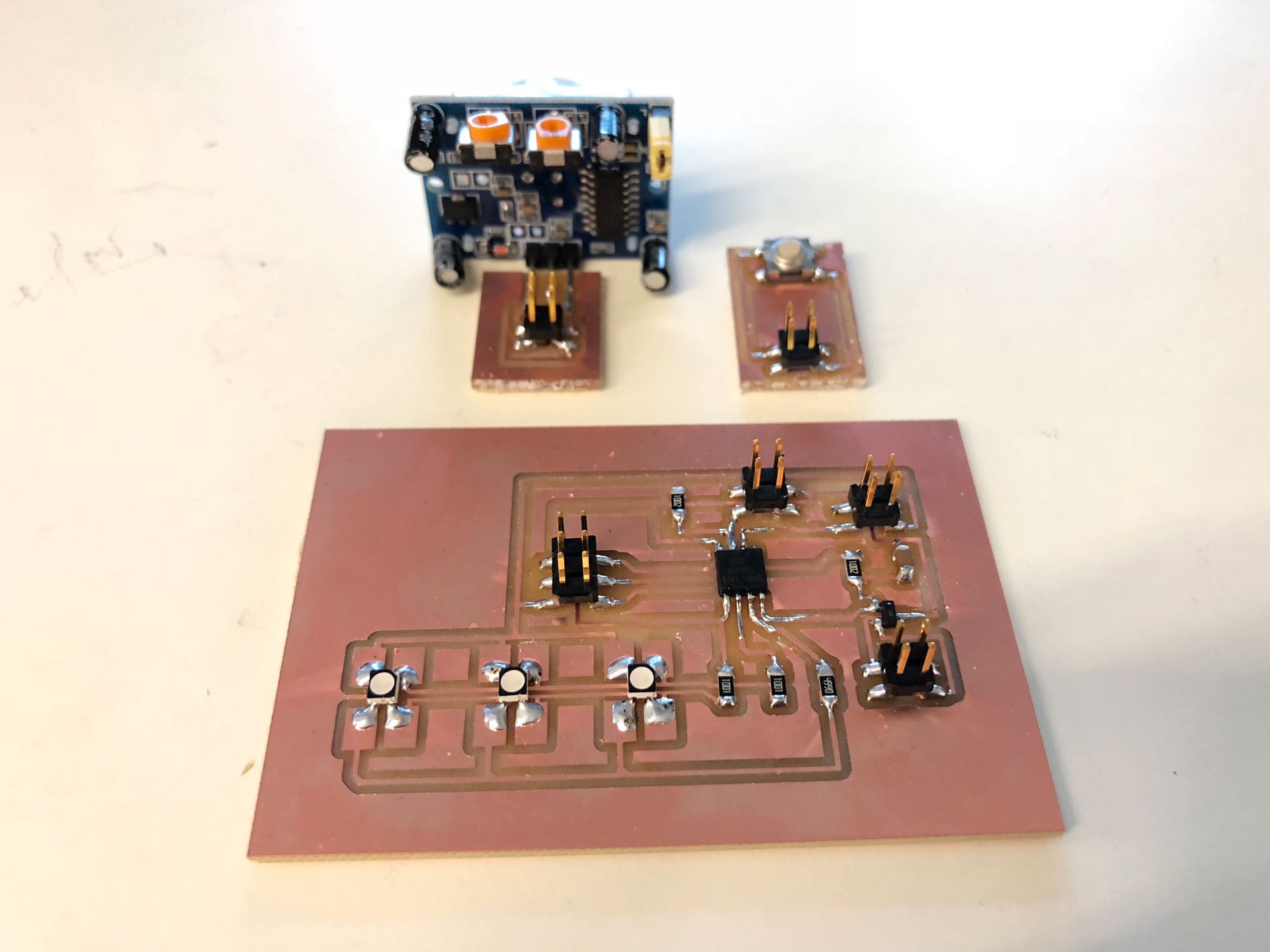
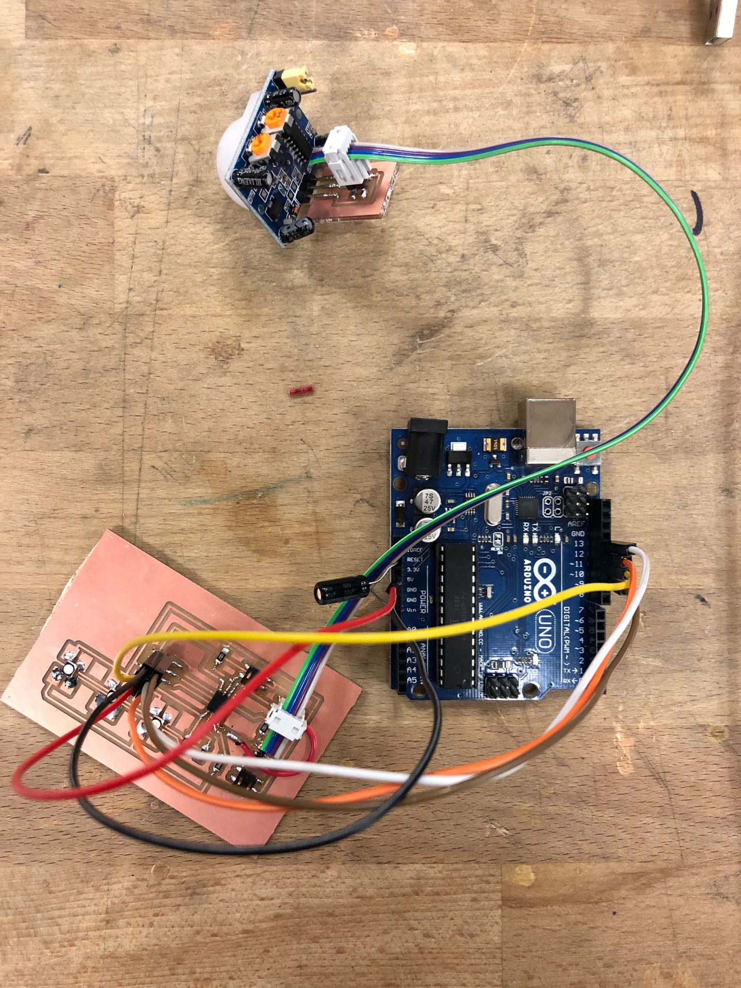
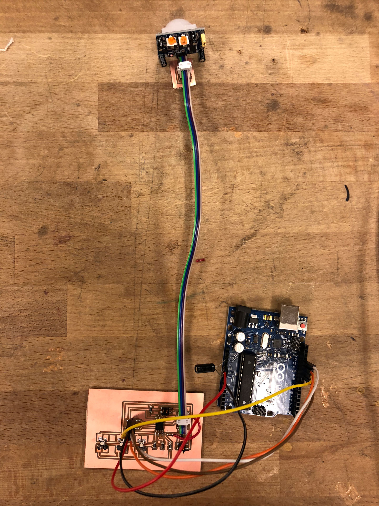
This week’s assignment was to add a sensor to a microcontroller board that I have designed and read it. I decided to combine this week’s assignment with next week’s assignment which is to add an output device to a microcontroller board I’ve designed and program it to do something. I decided to create a board that uses an ATtiny45 microcontroller, and has headers that connect to separate boards with each board containing a type of sensor. The two types of input devices that I used include a PIR sensor and a button. My output device includes 3 RGB LEDs. Ultimately, I would like to use this setup as part of my final project which is an “Interactive TV” - a storage unit, lighting element, and game console.
Eagle
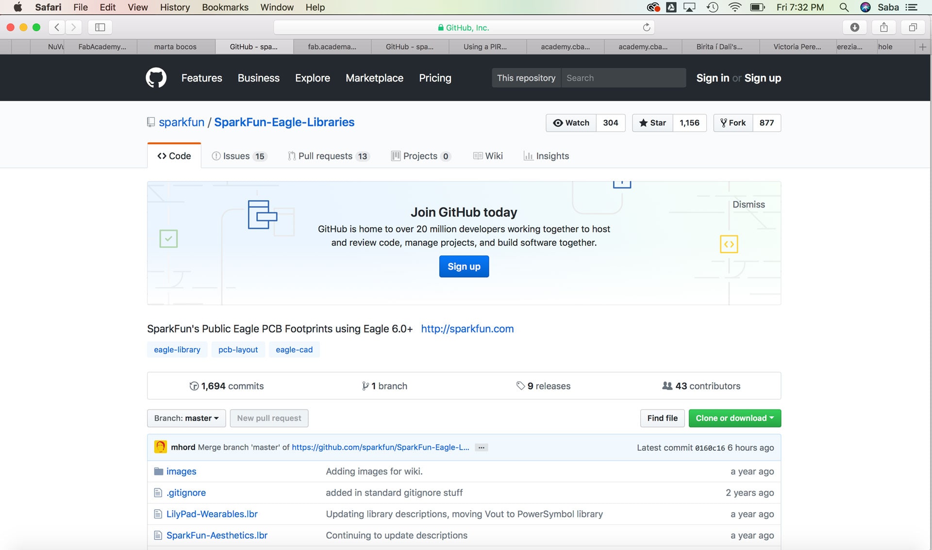
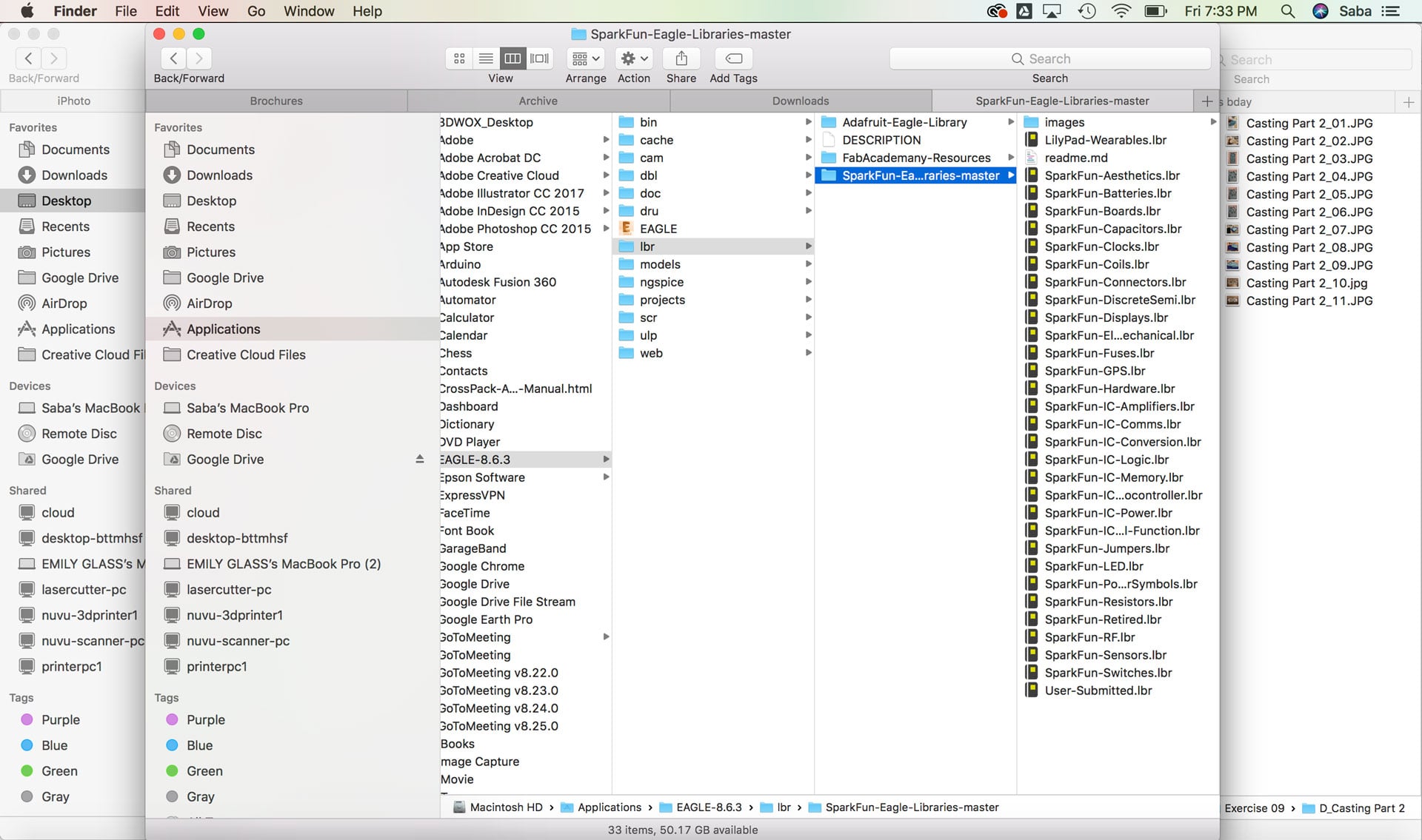
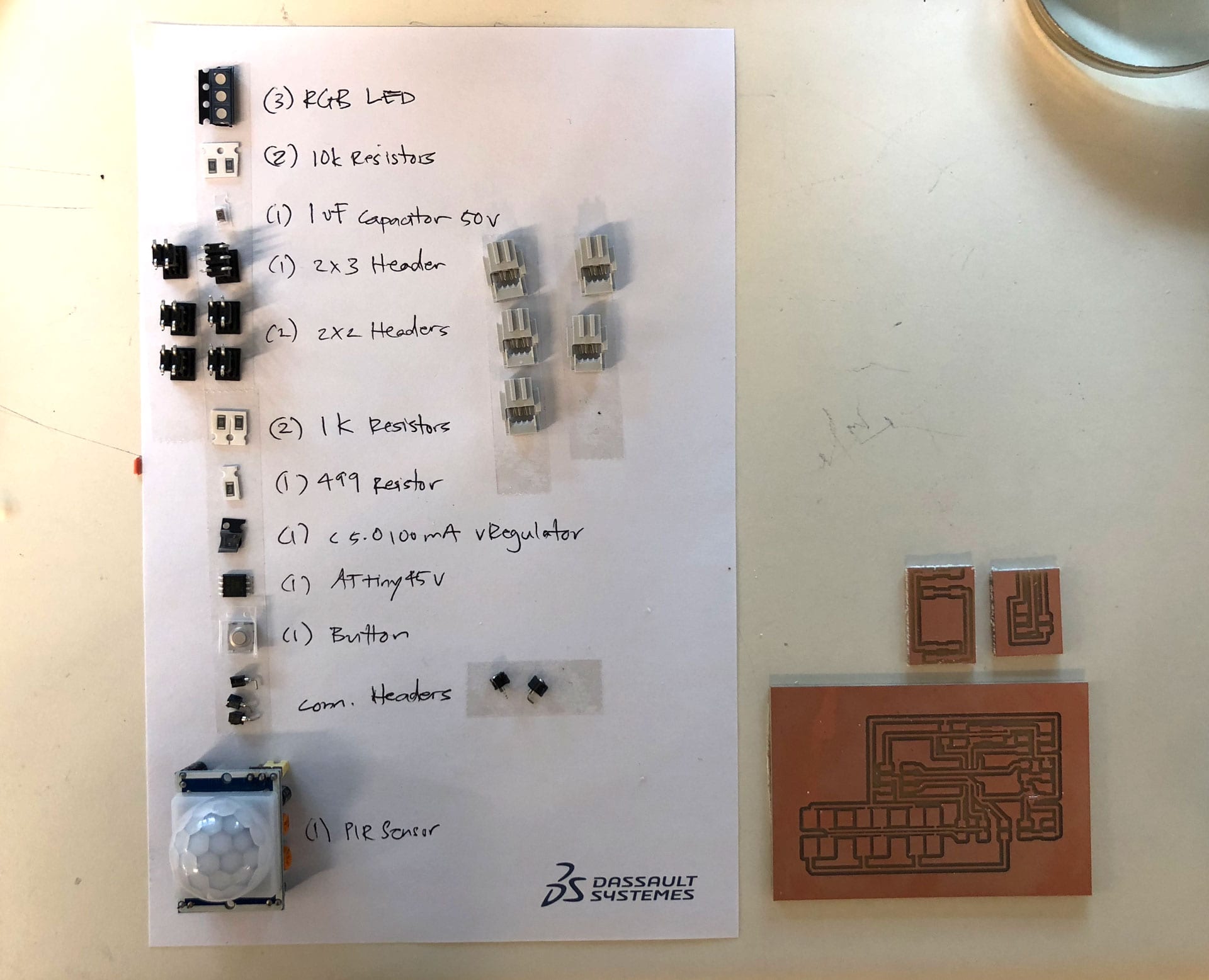
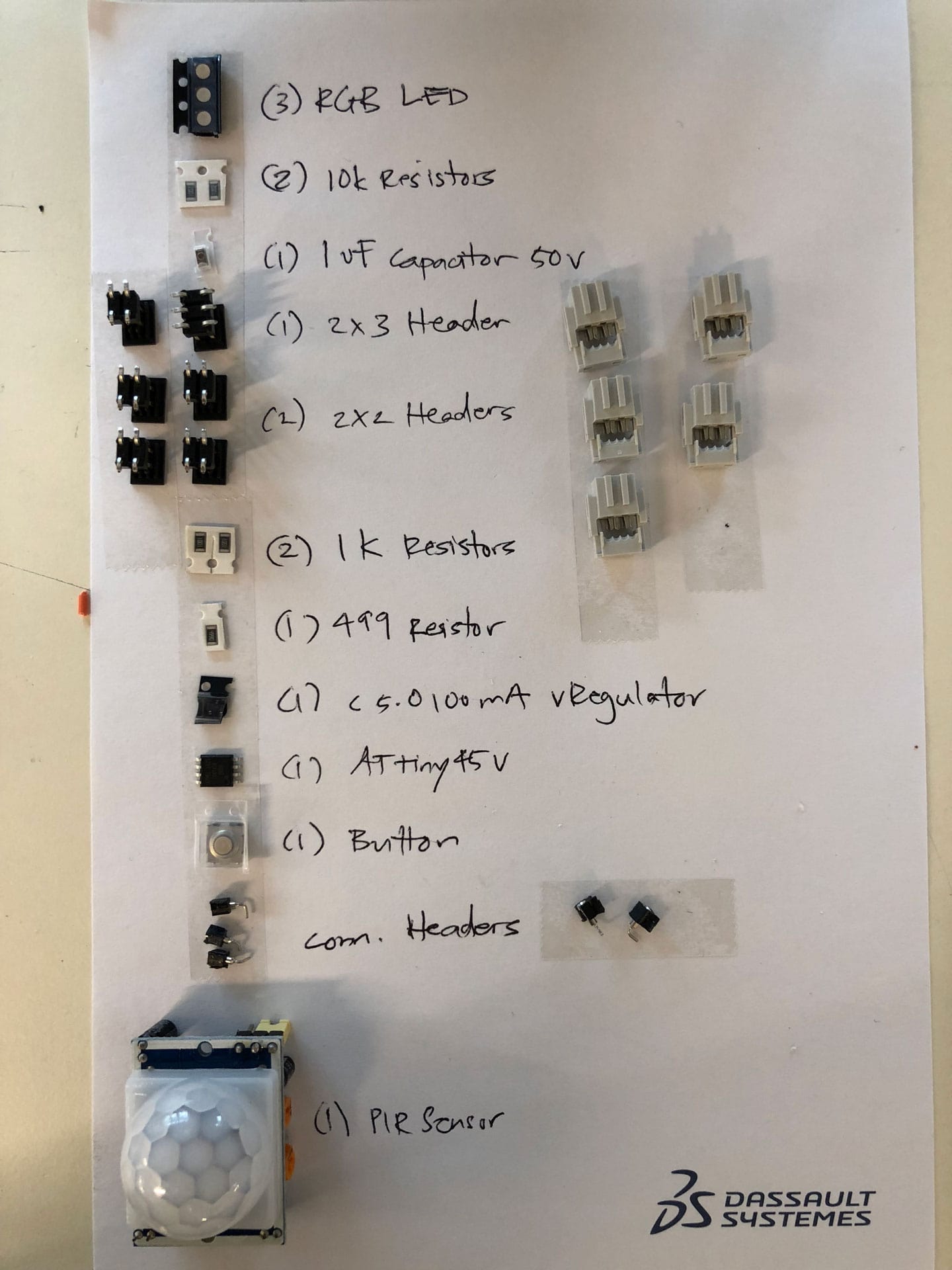
I began by designing the schematic for my 3 boards in Eagle. I first downloaded the Sparkfun components library so I would have access to the sensor and other components and added it to my Eagle Library resources folder. Here is a list of the components that I used on each board.
Main Board Components:
PIR Board Components:
Button Board Components:
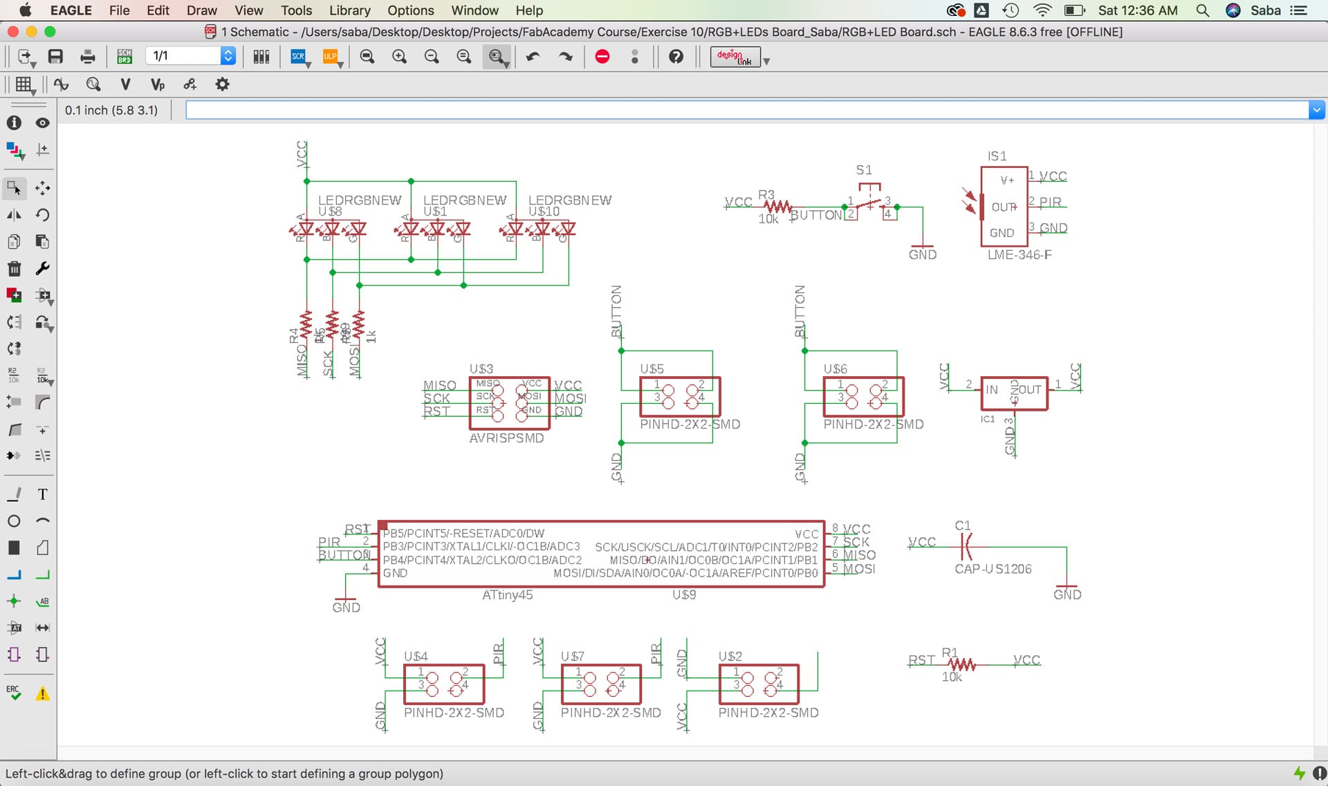
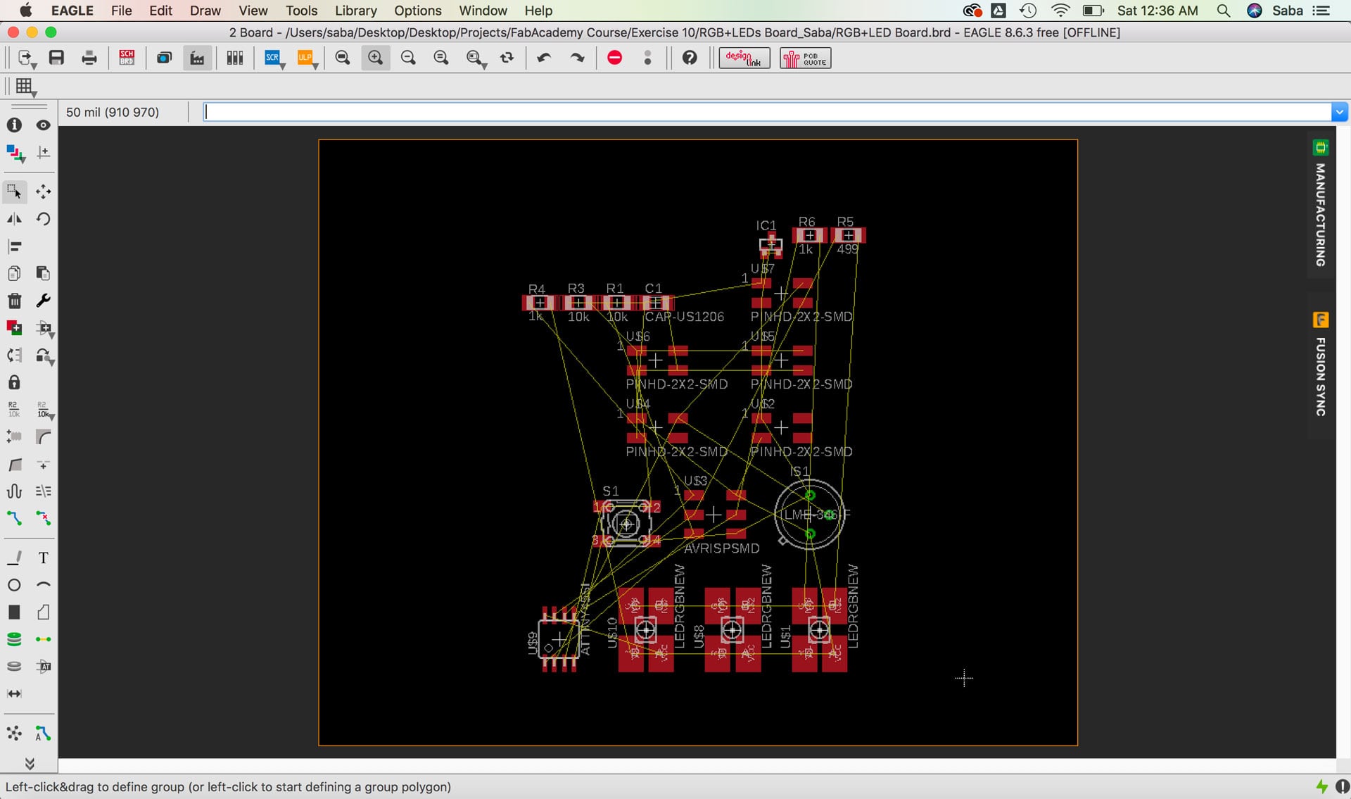
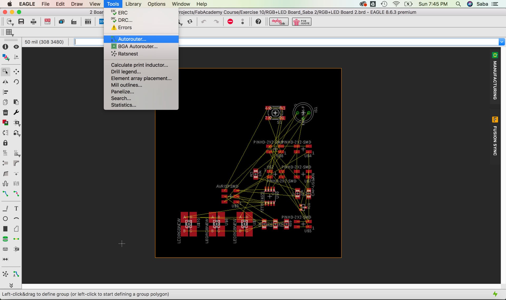
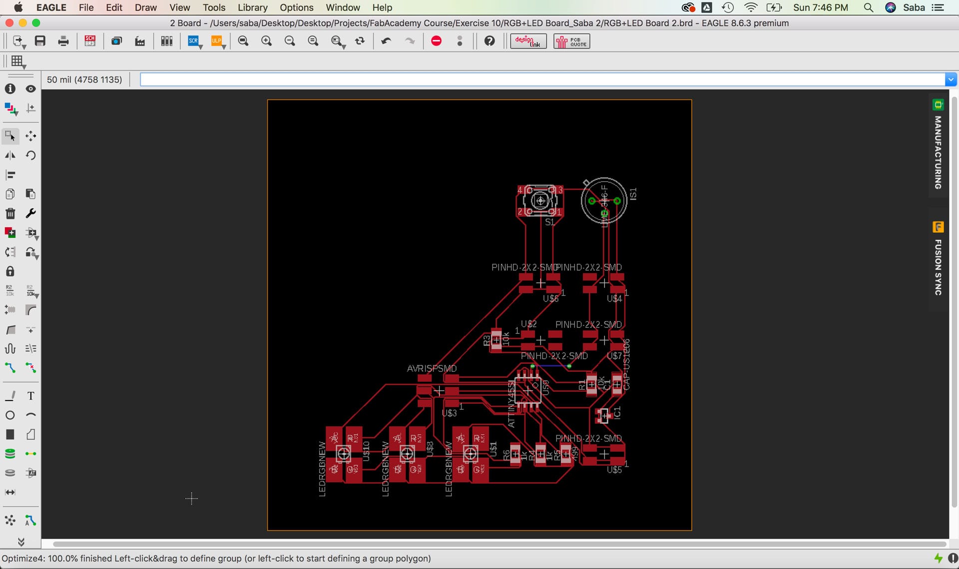
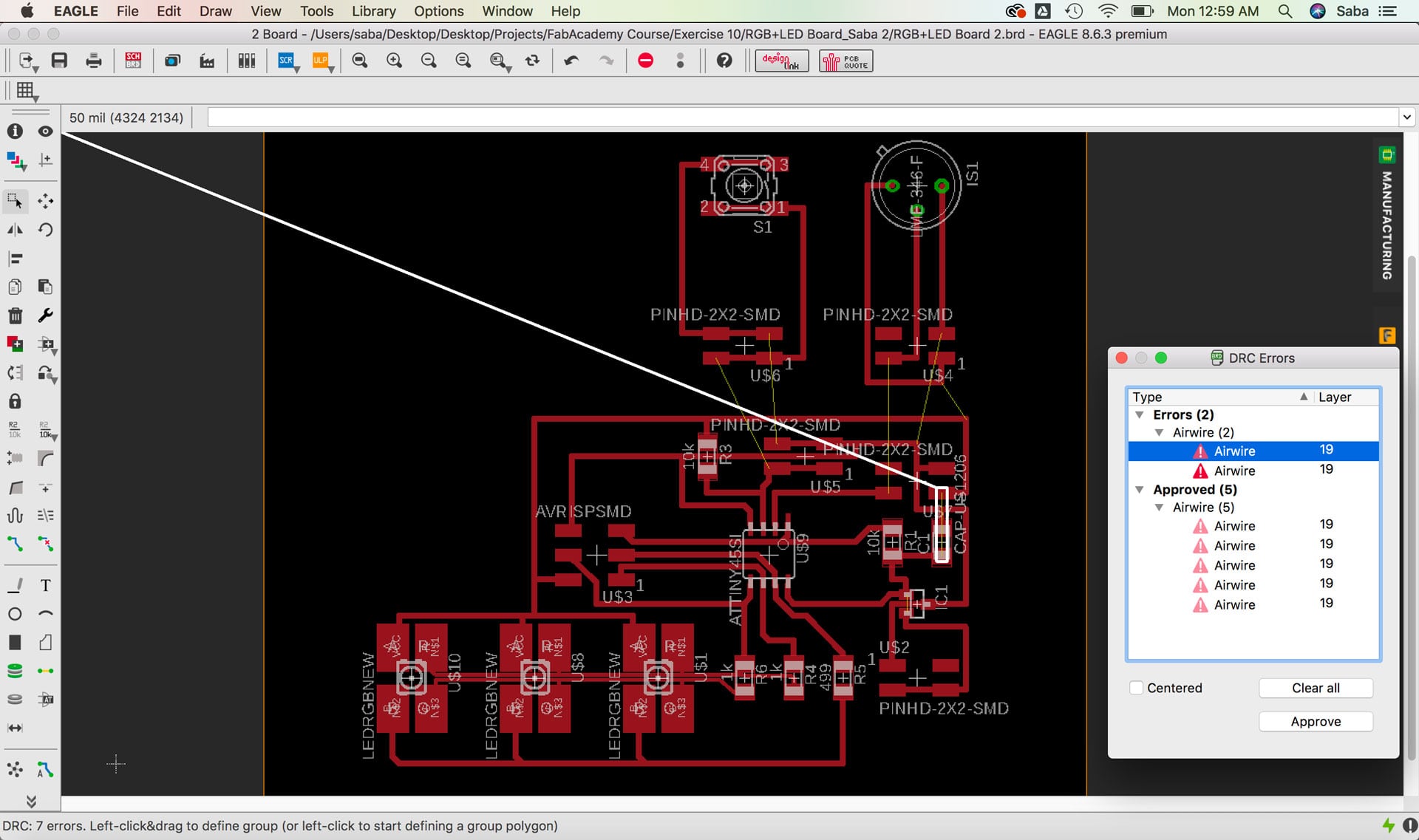
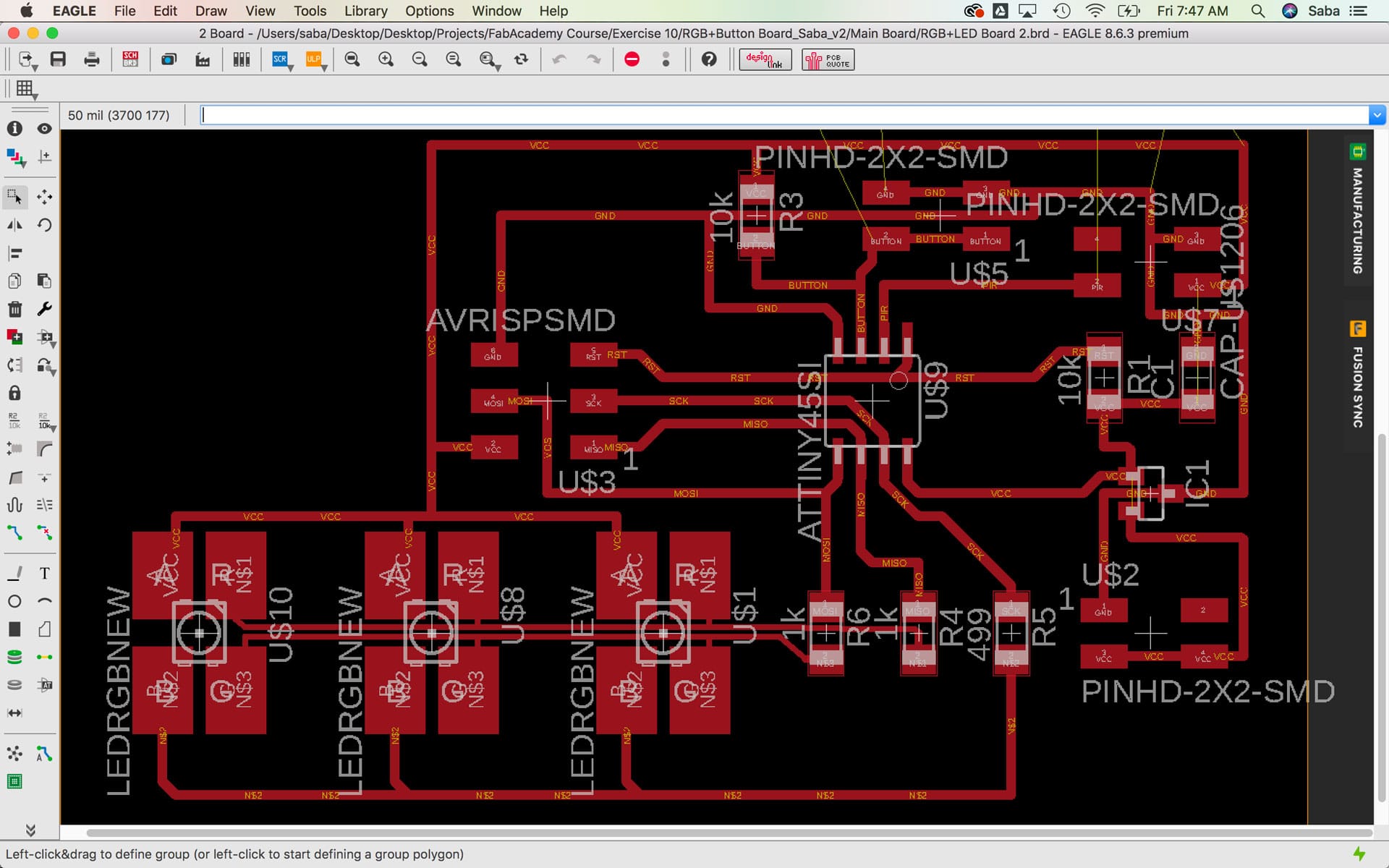
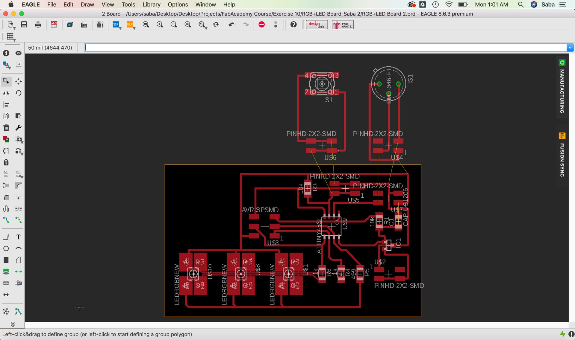
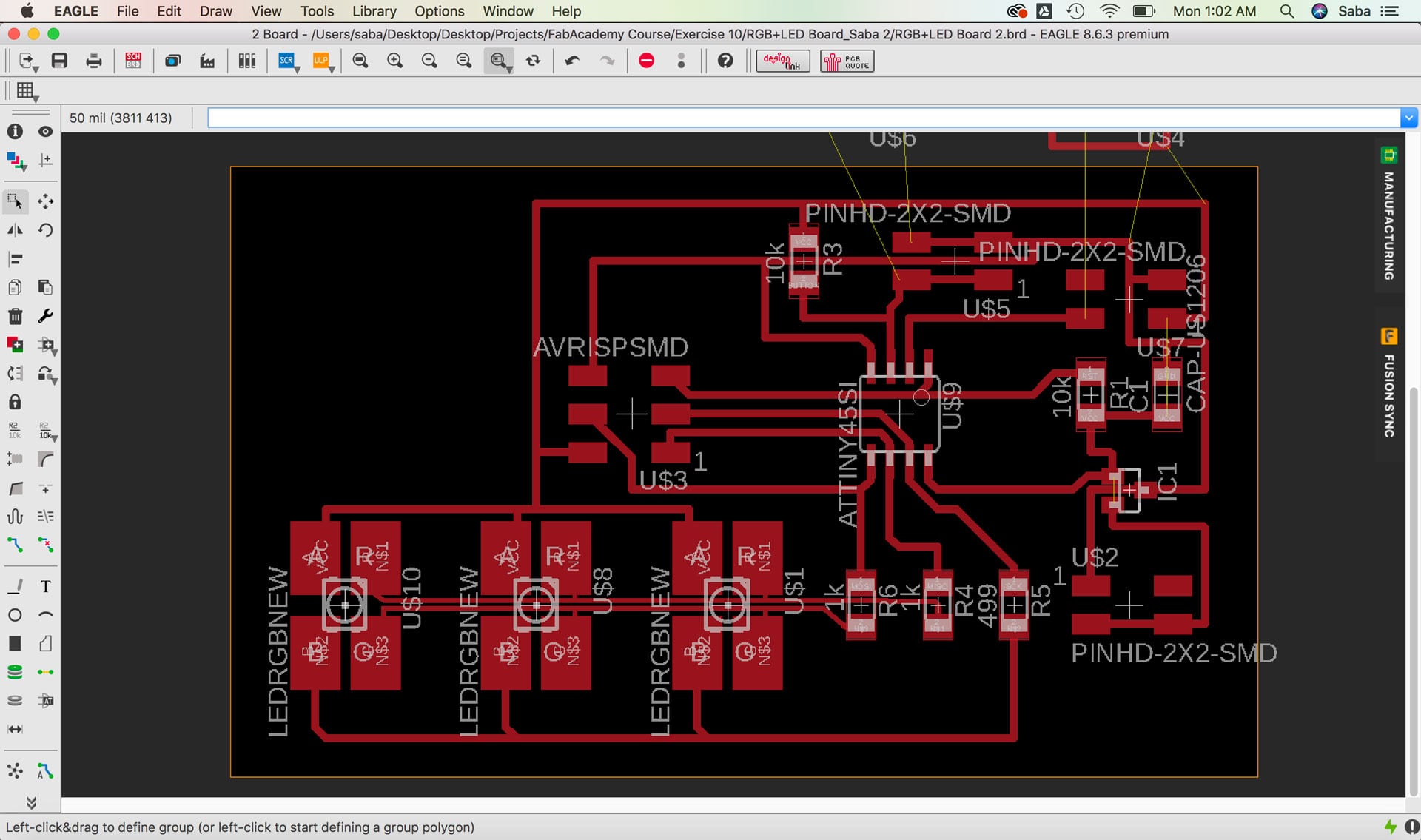
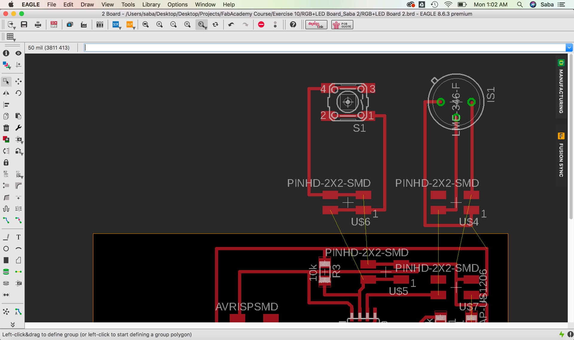
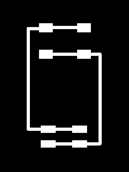
I then laid out my board components in the Schematic View and created the board in the Board View. I used the Autorouter feature to route the traces, but it didn’t work perfectly given the width of the traces and the spaces in which they would need to run, so I manually updated the routes by using the “Ripup” command and re-routing the traces.

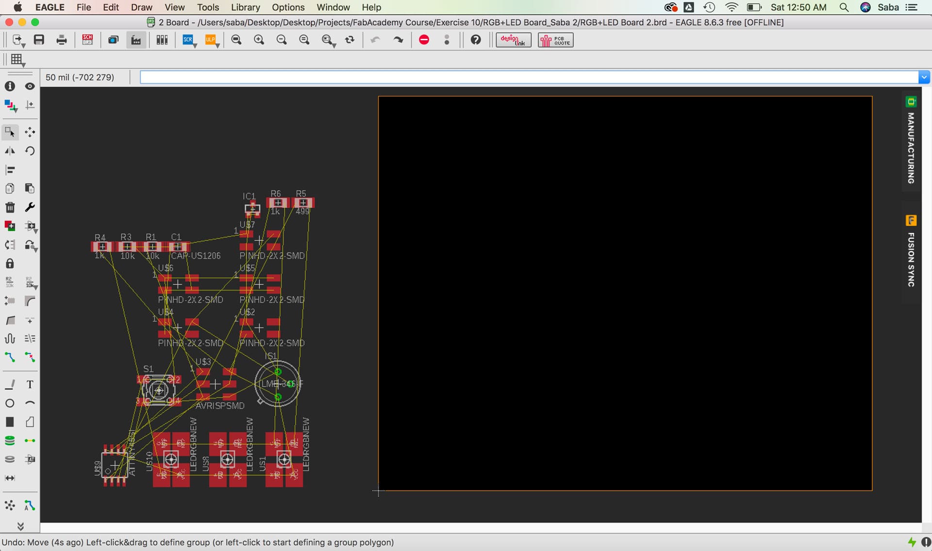
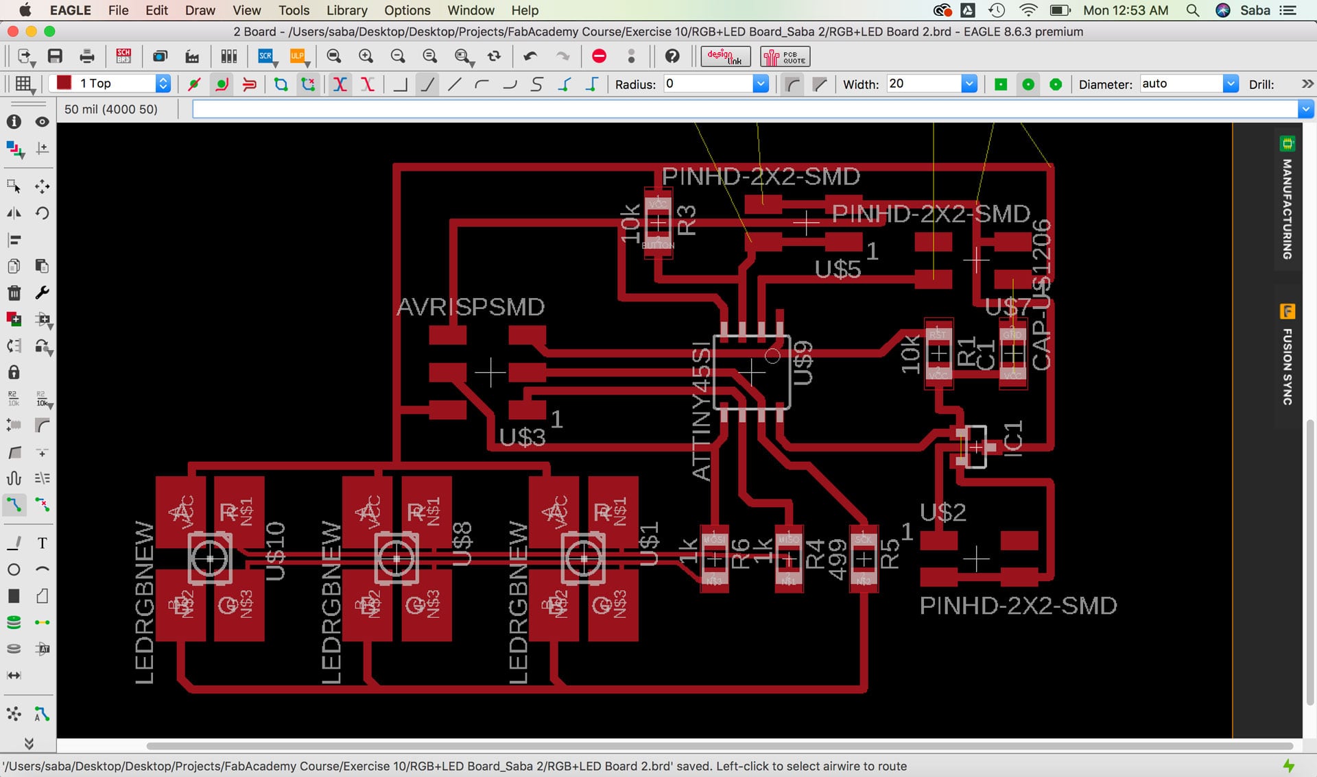
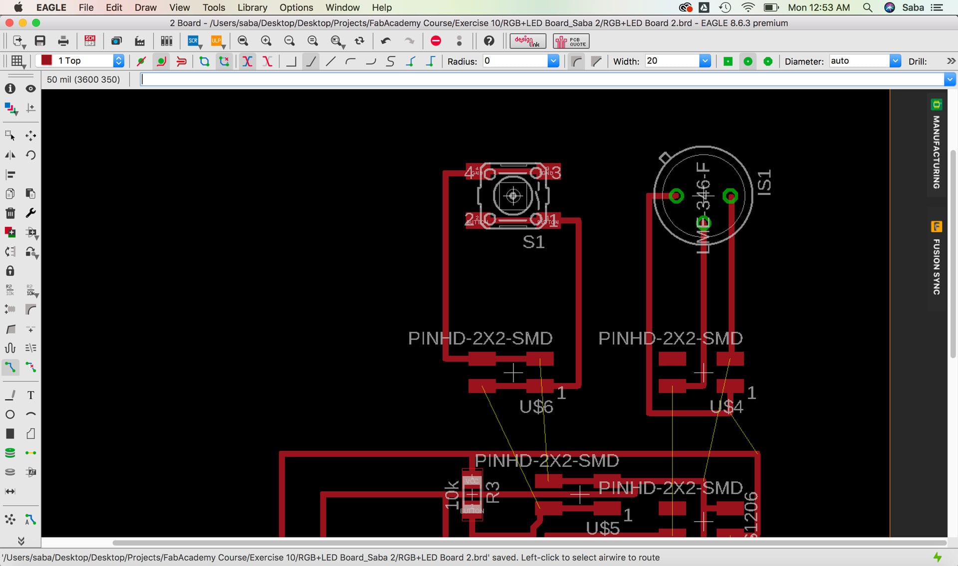
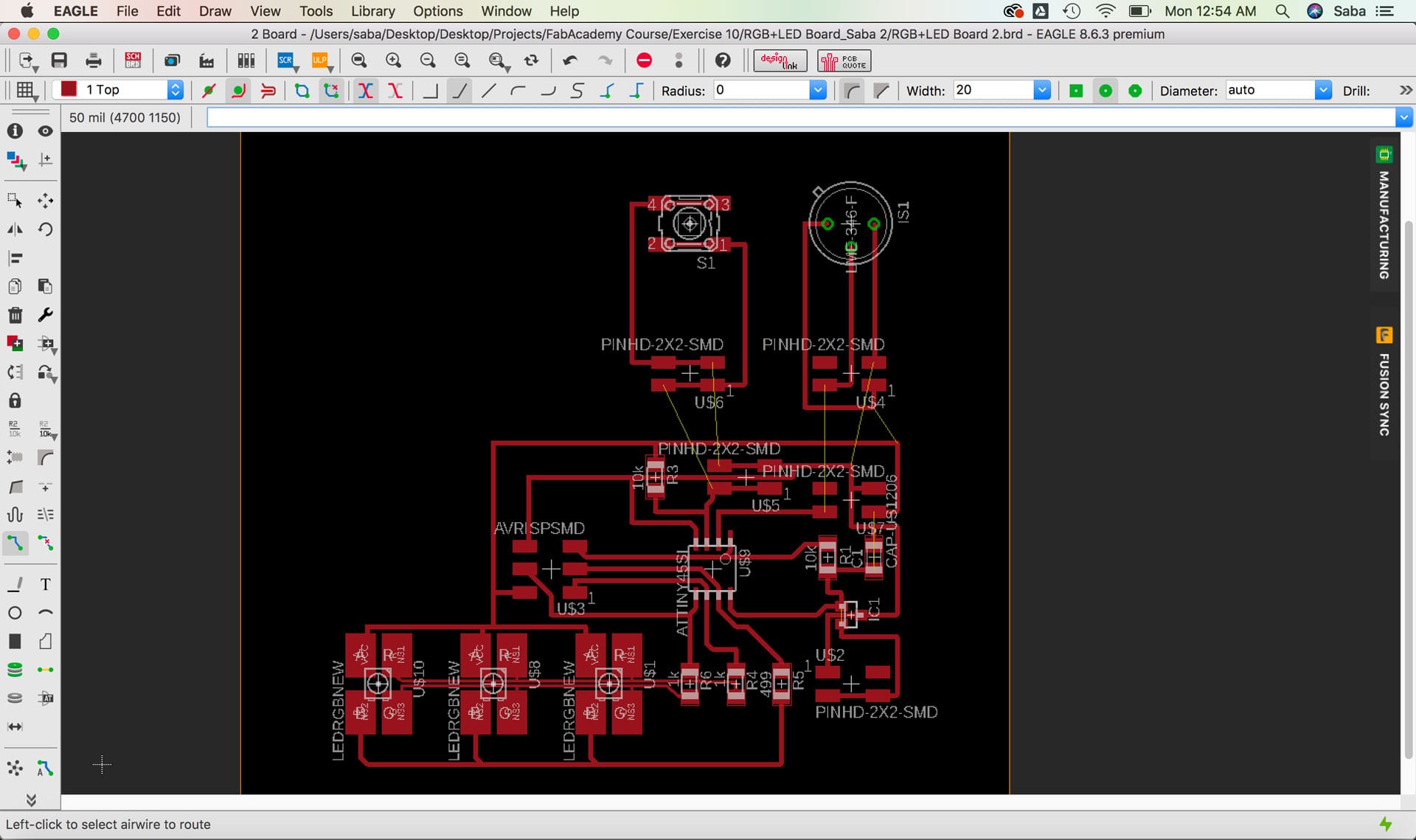
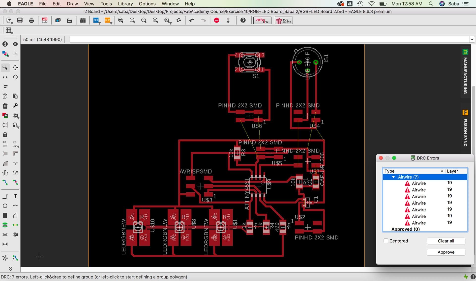
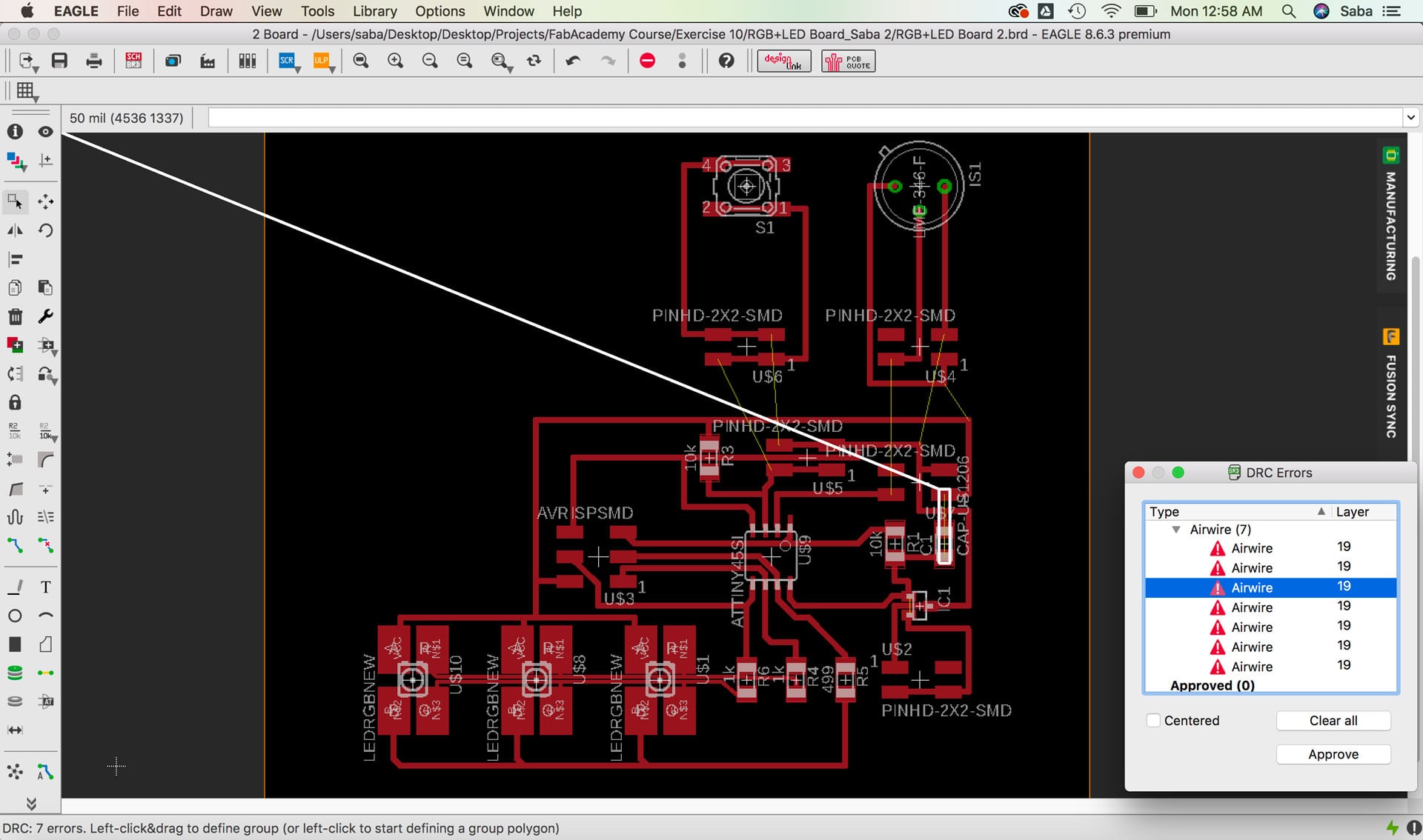
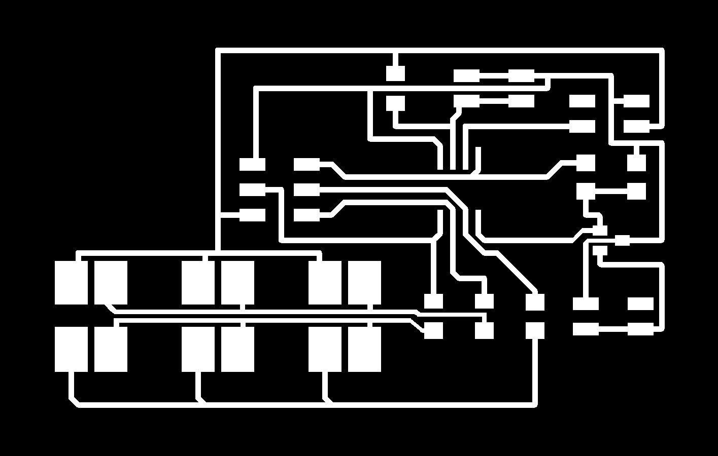
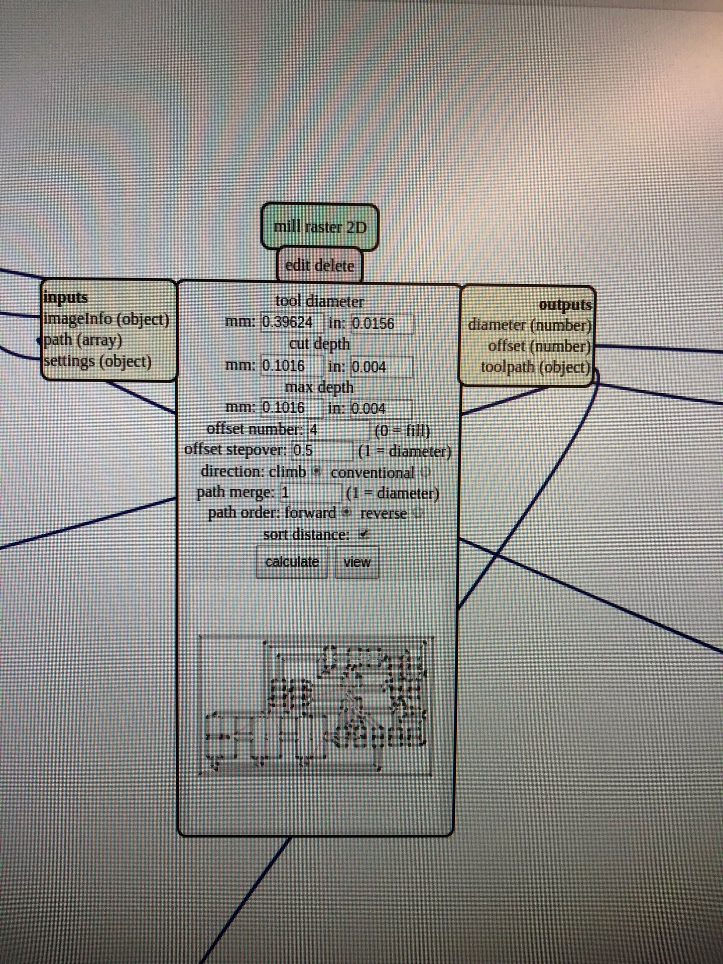
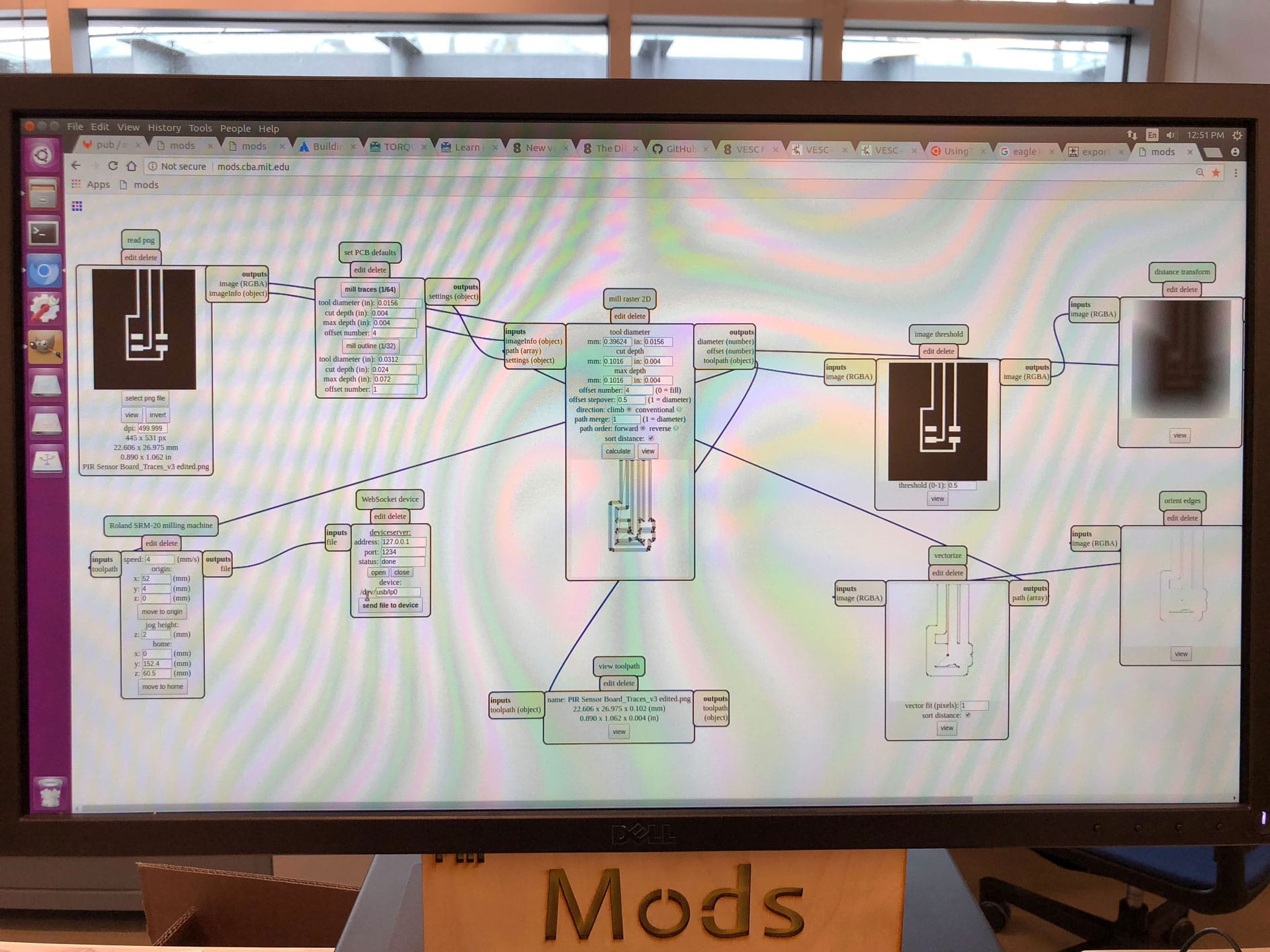
I then ran the DRC command with the Fab Academy design rules and discovered a few errors. I corrected most of them and thought that the remaining error was not correct (this would come back to haunt me later!). I created trace and outline PNGs for all 3 boards.


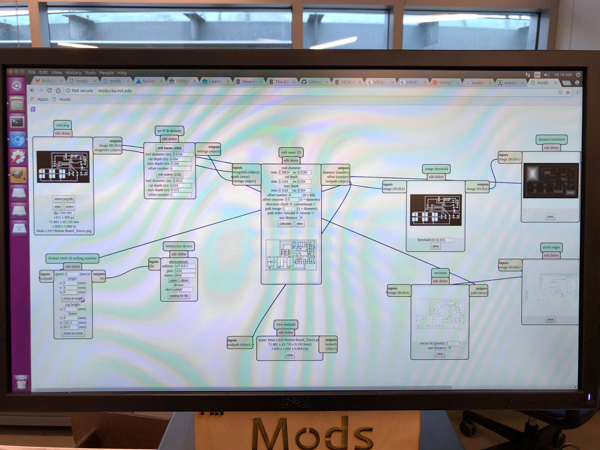
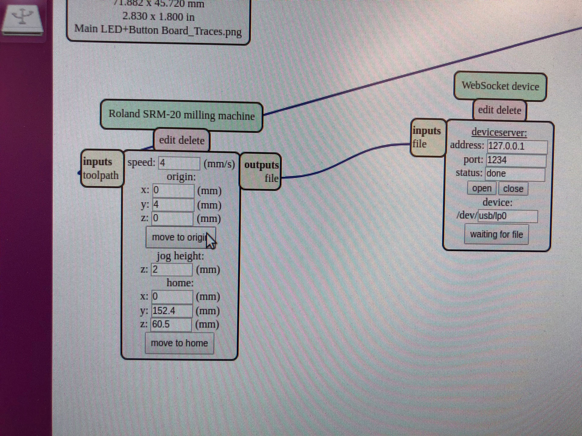
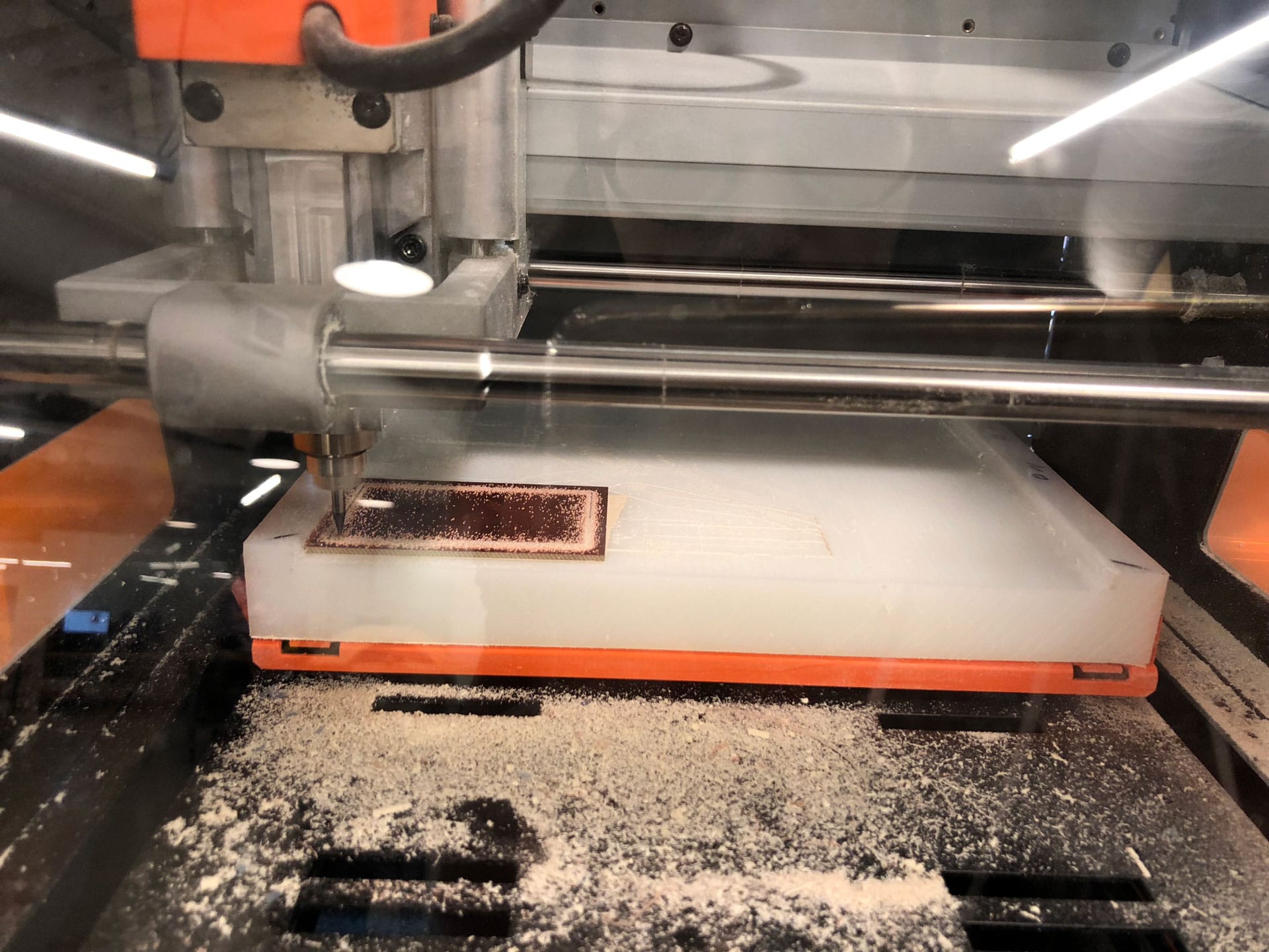
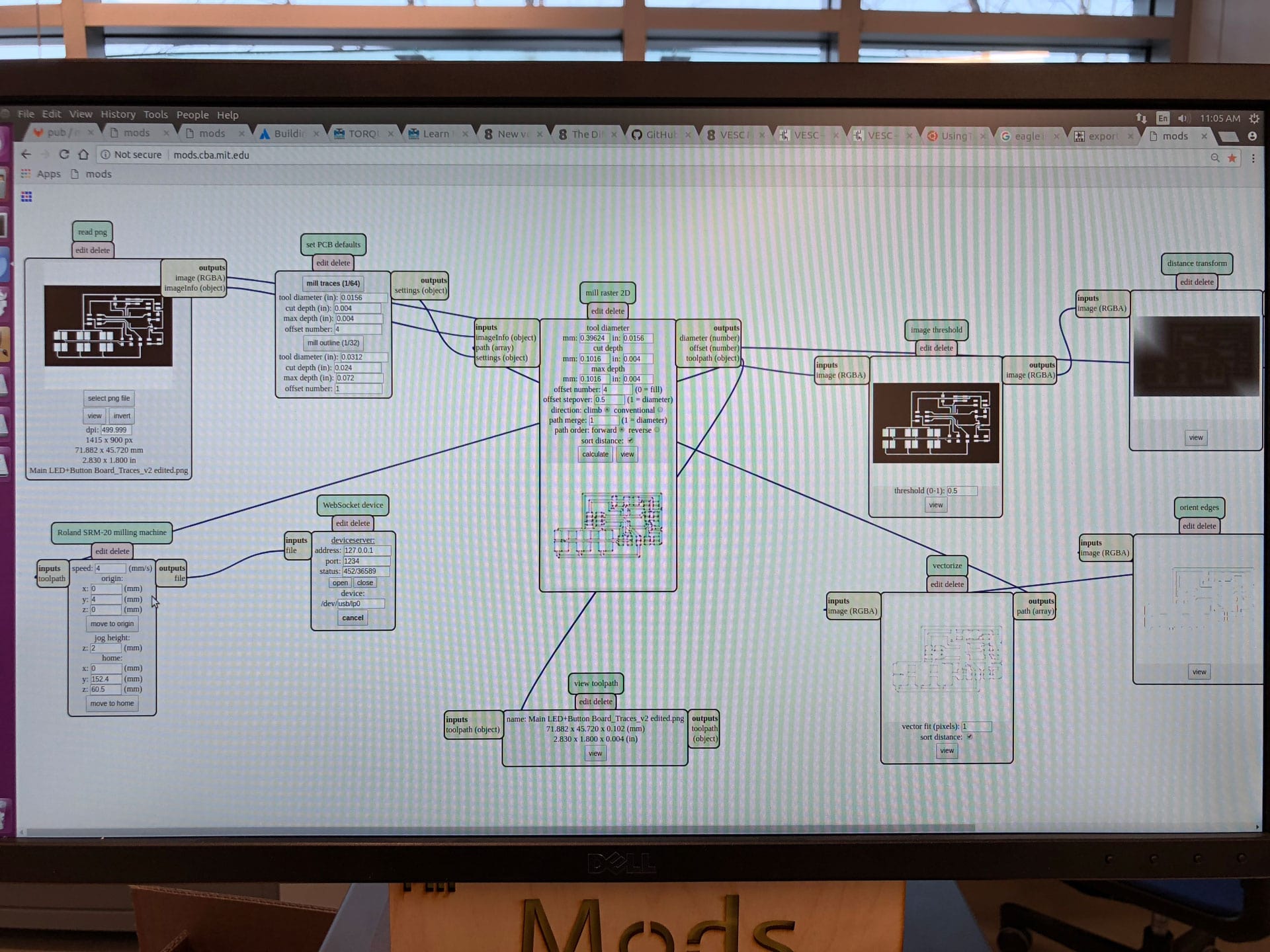
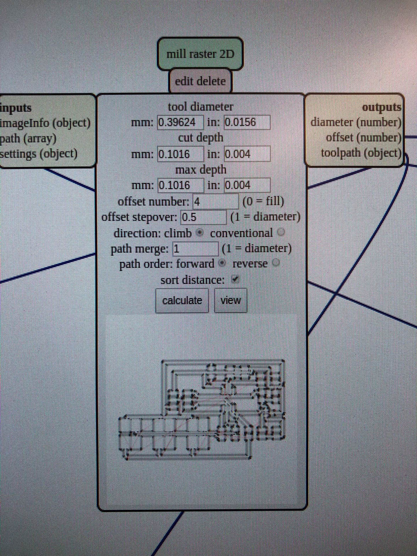
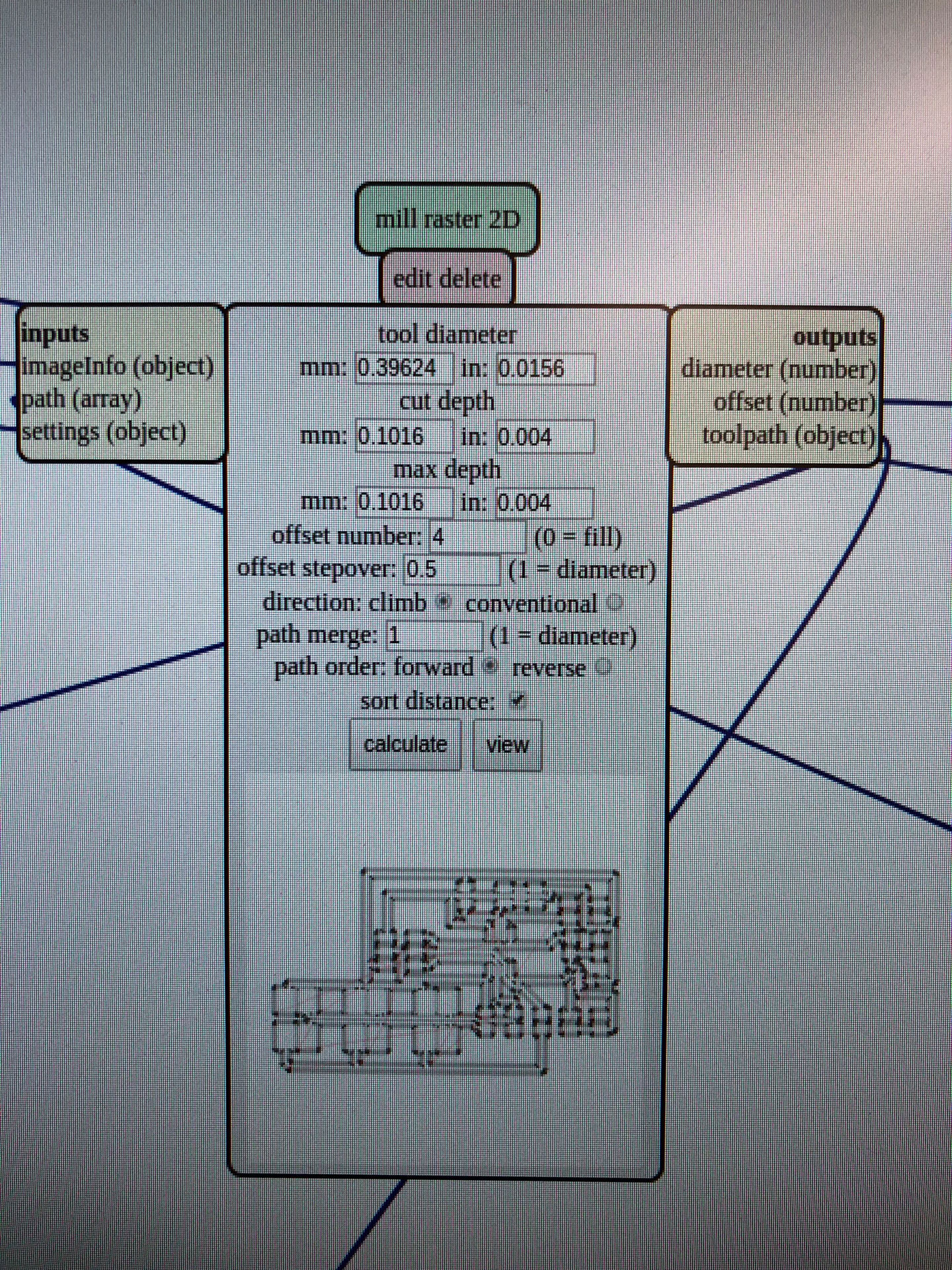
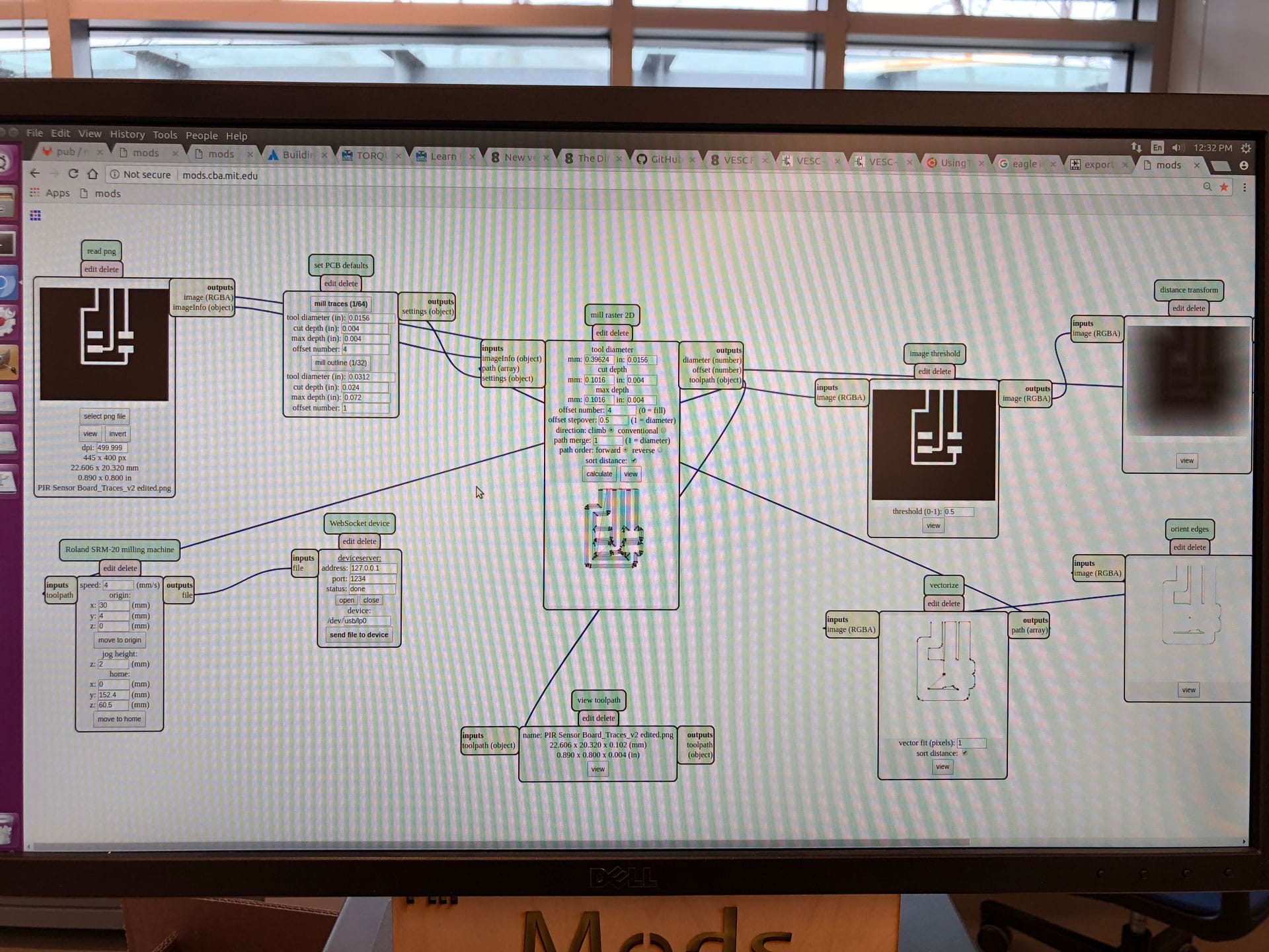
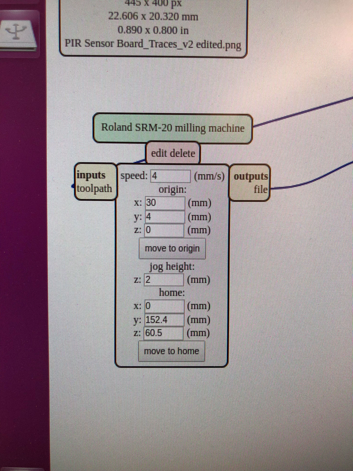
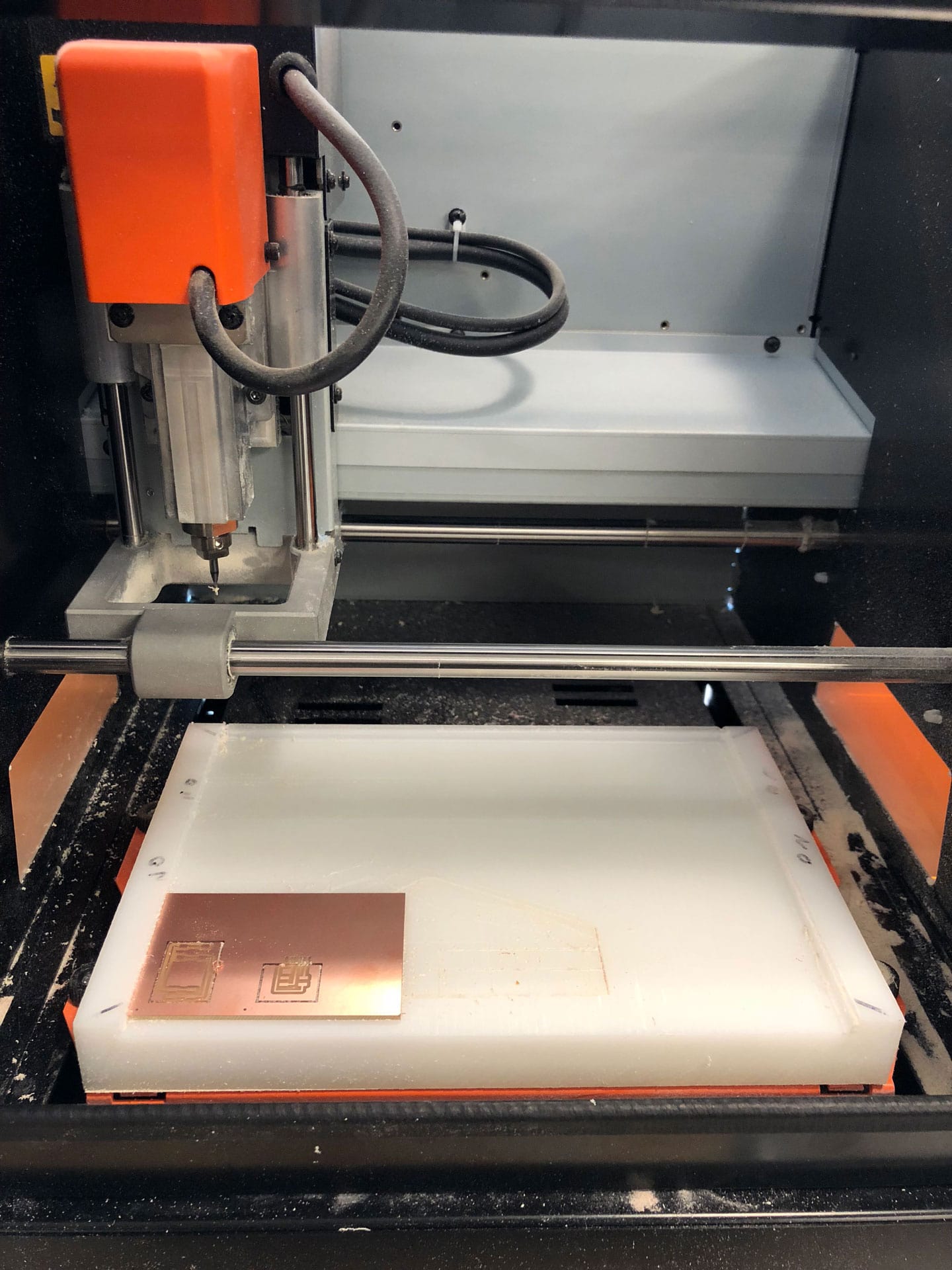
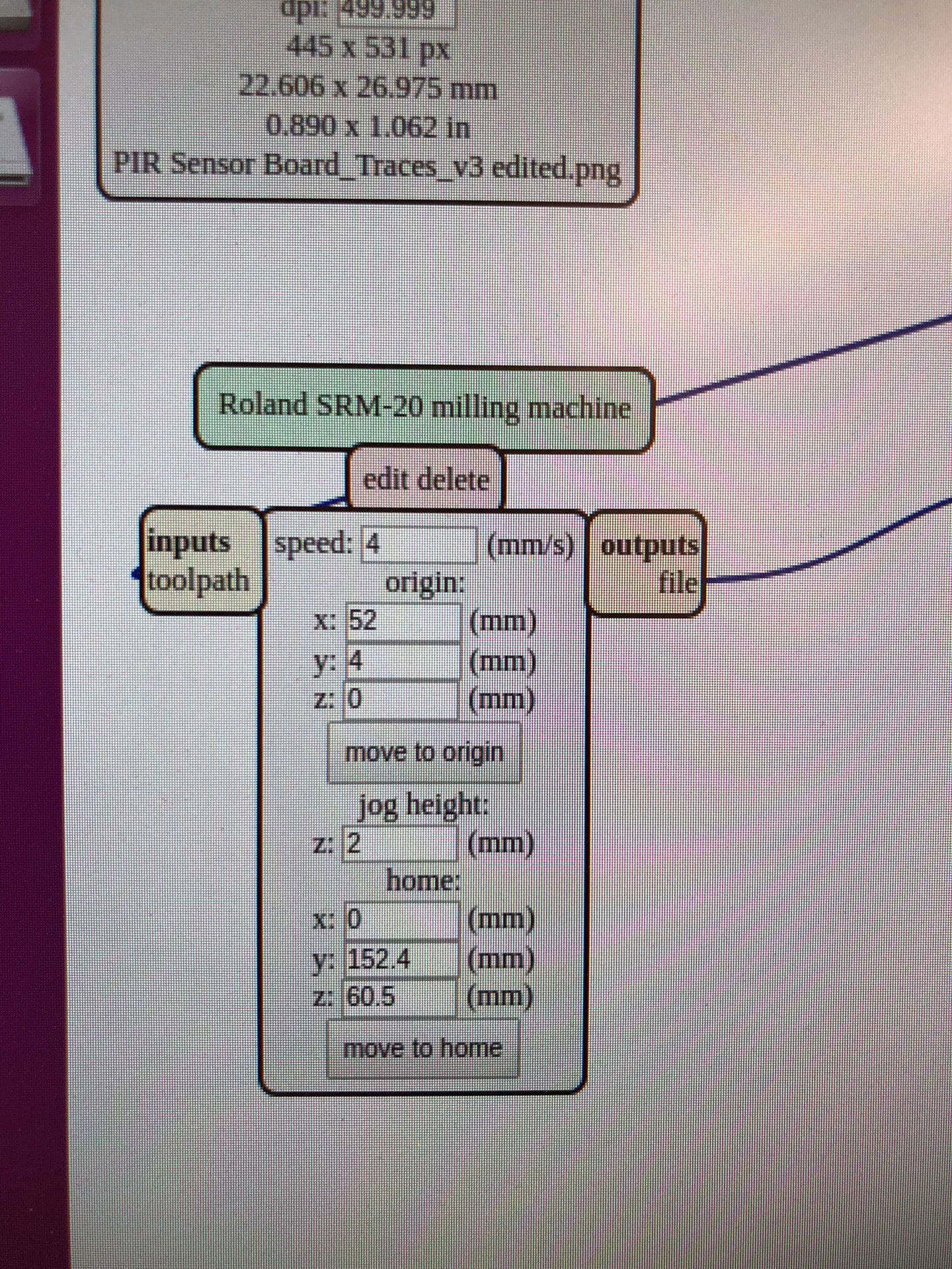
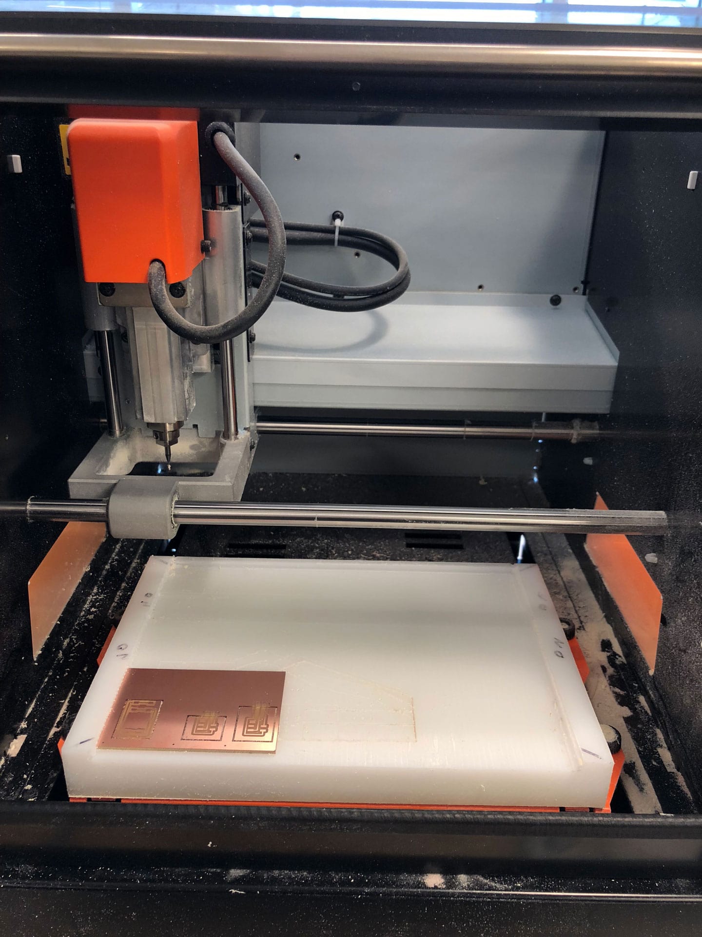
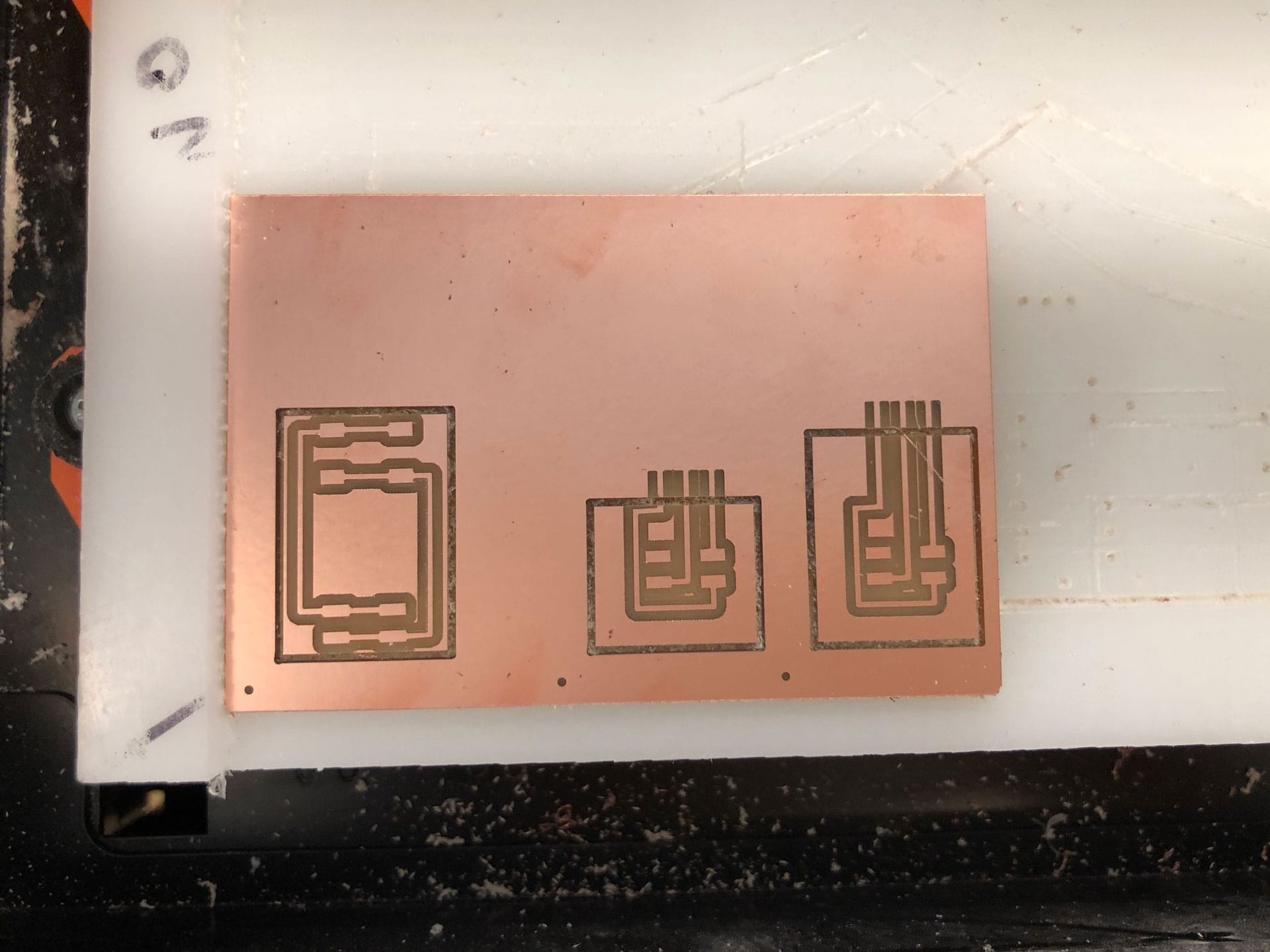
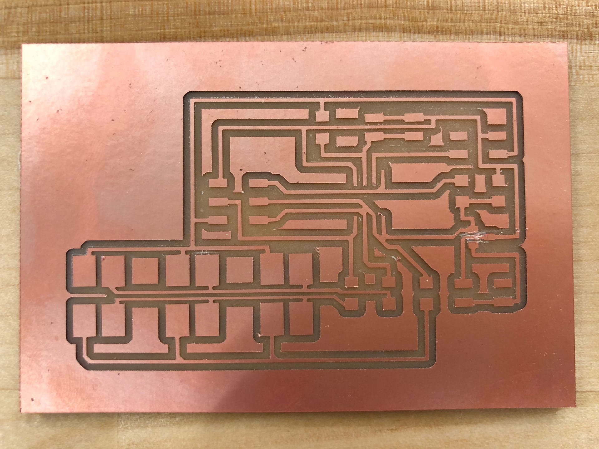
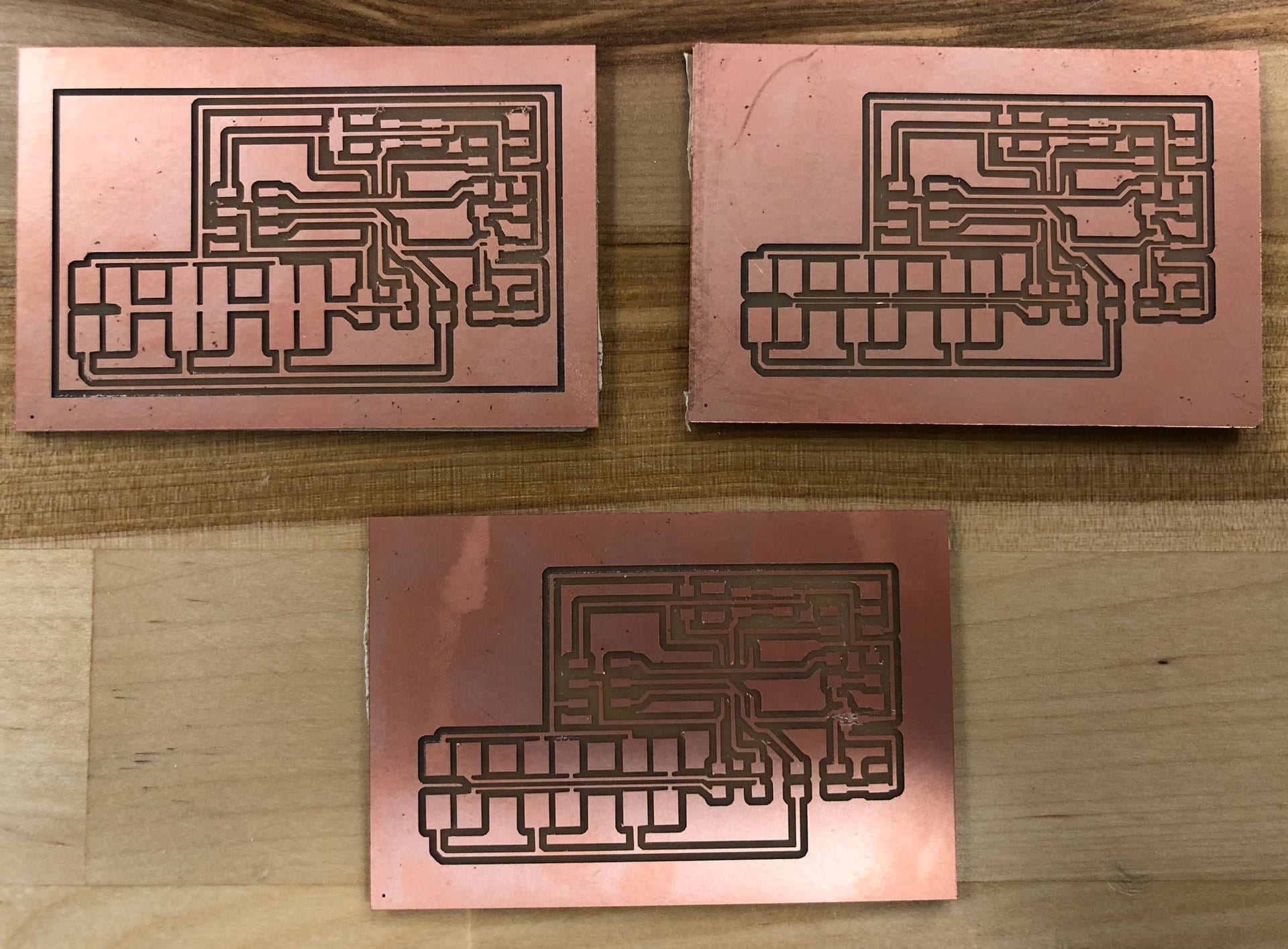
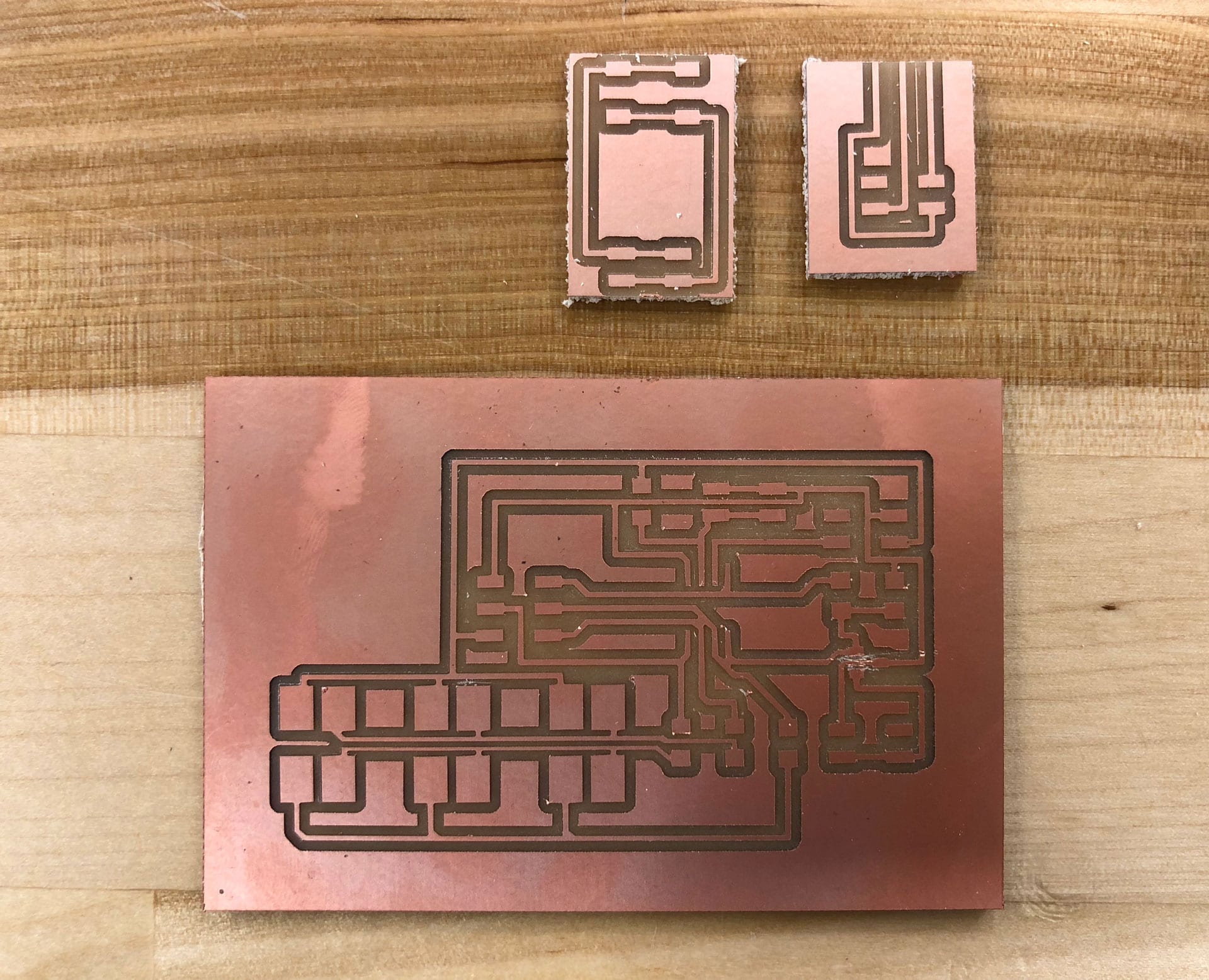
Milling
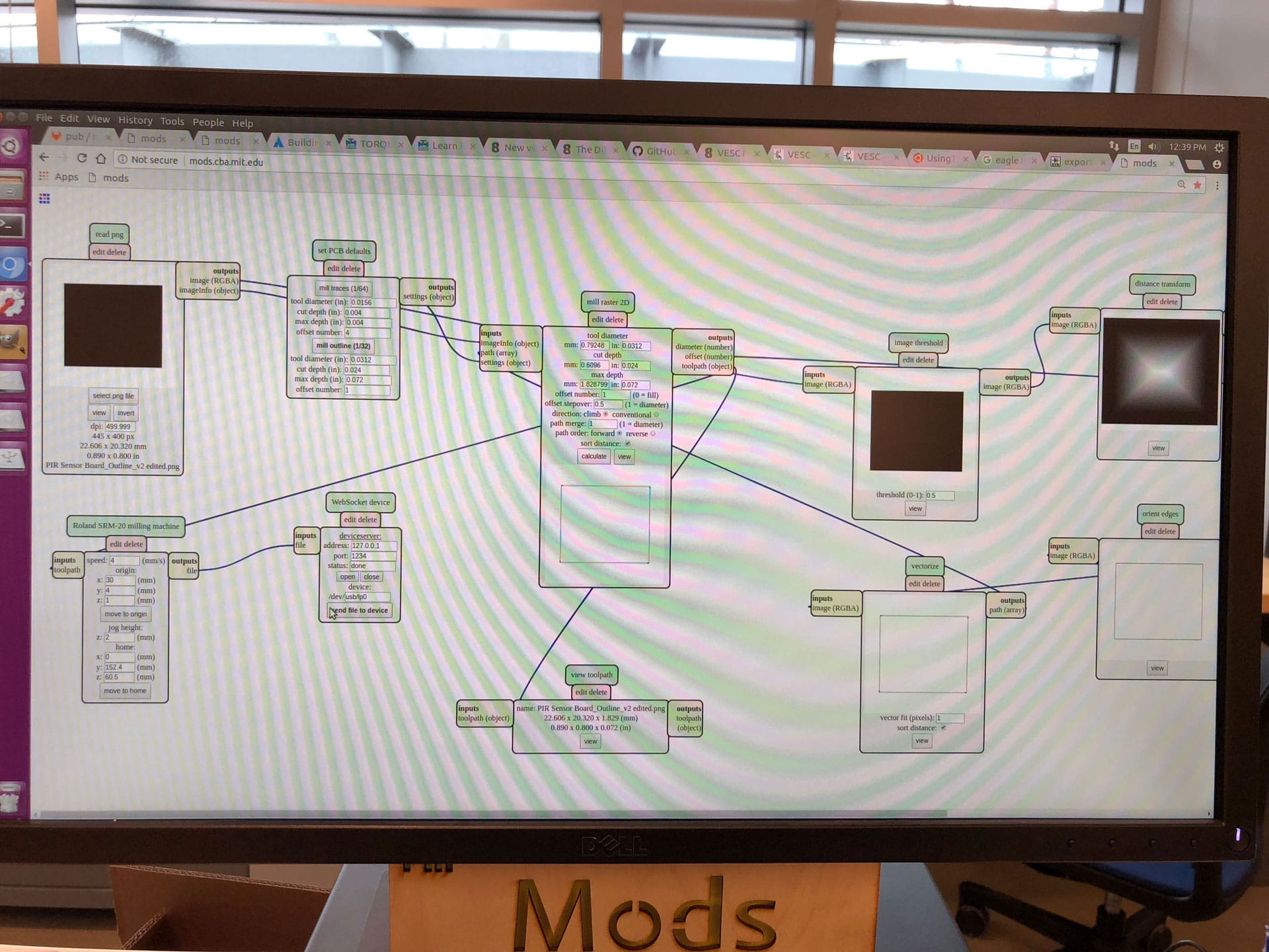
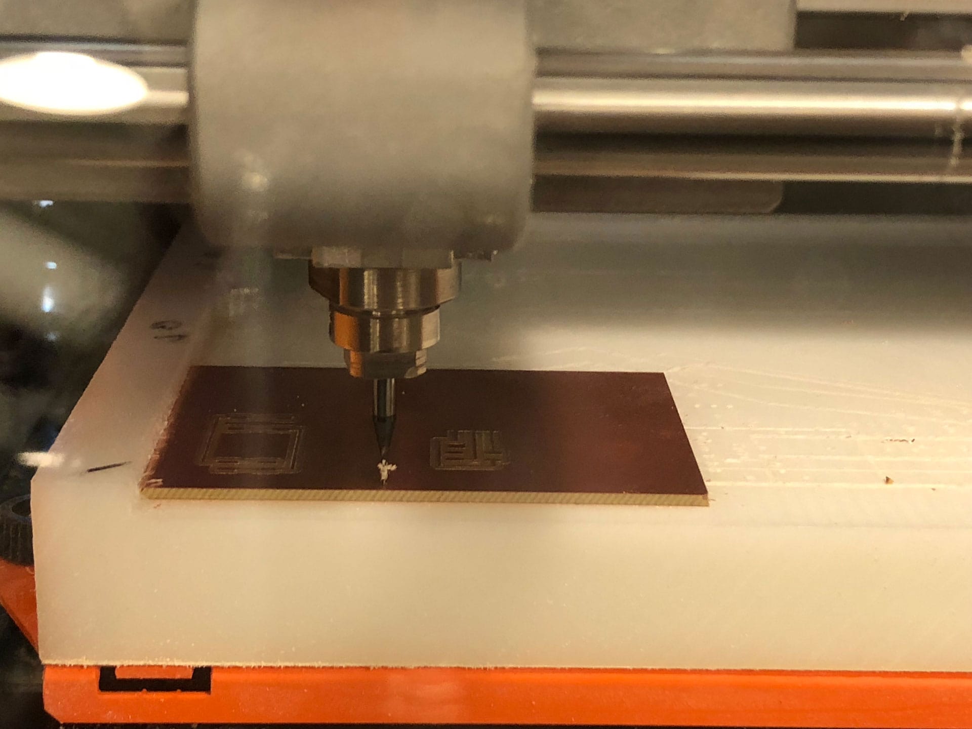
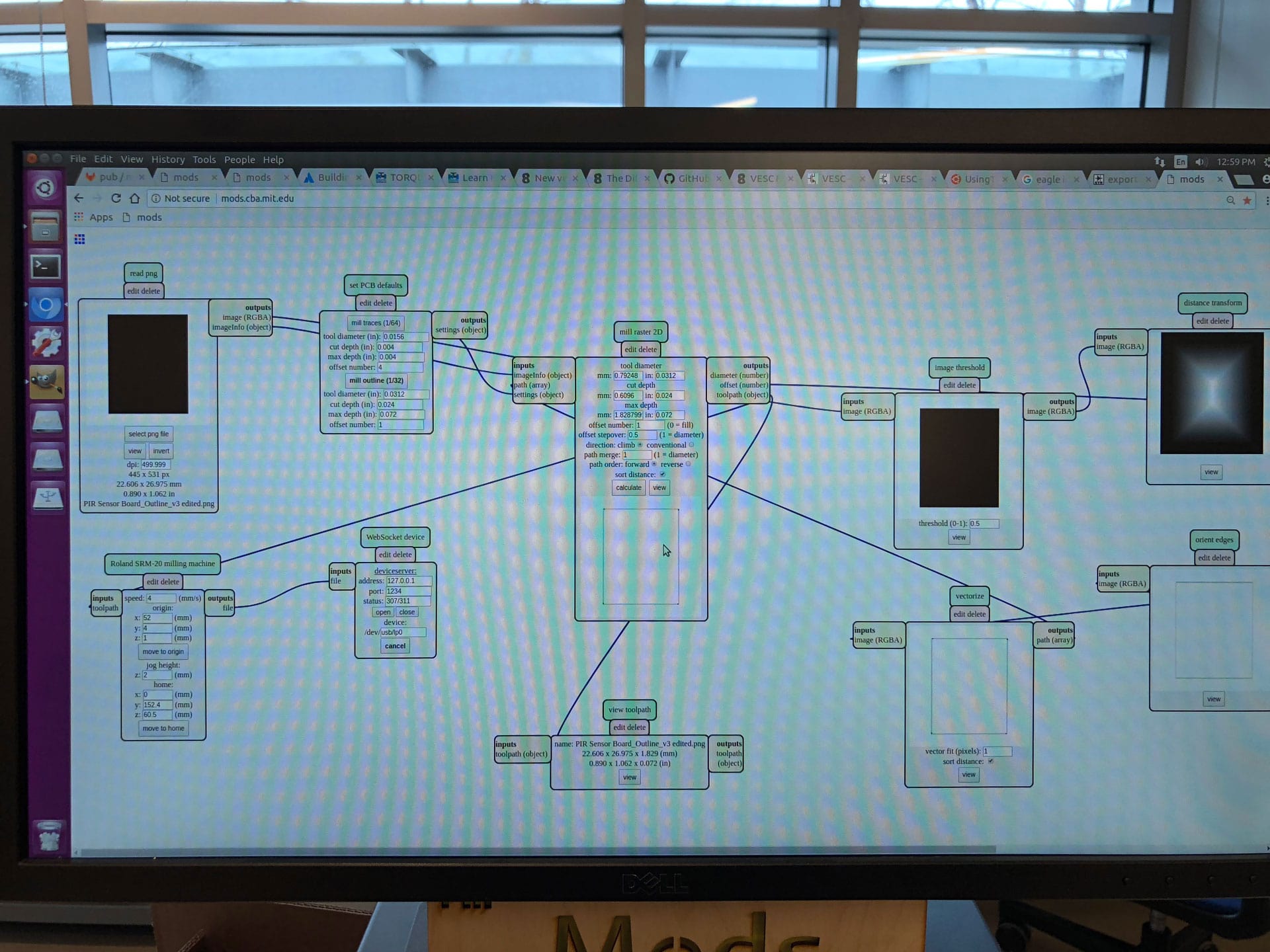
The next part was milling the board. I used our Roland CNC machine to mill the boards. The first attempt to mill the board didn’t work very well, and I had to return back to my PNG files and modify the pads and traces so there would be more room in between for the cutting area. The second attempt worked much better.
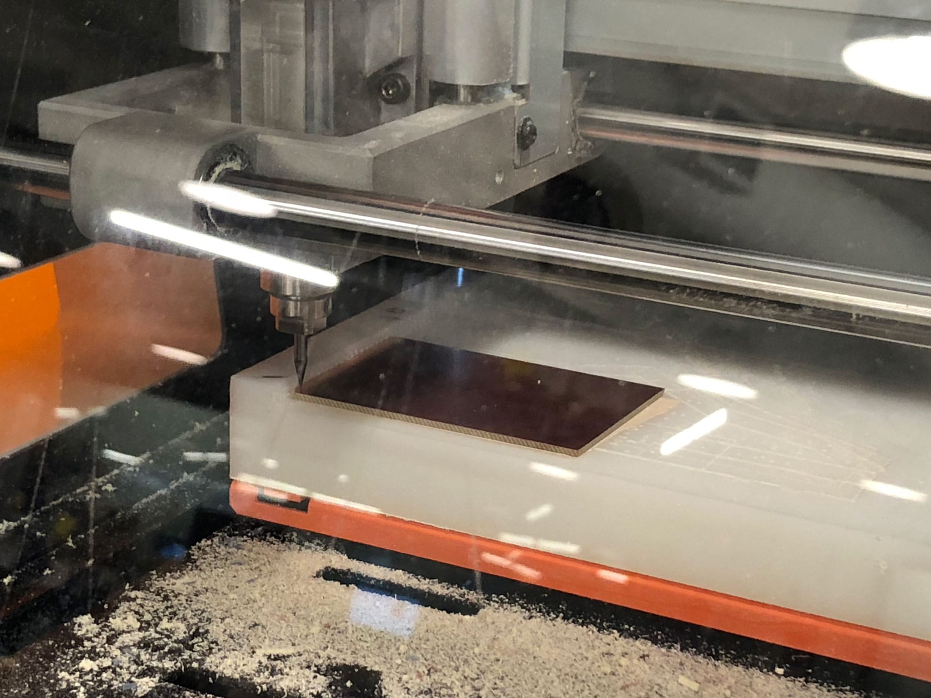
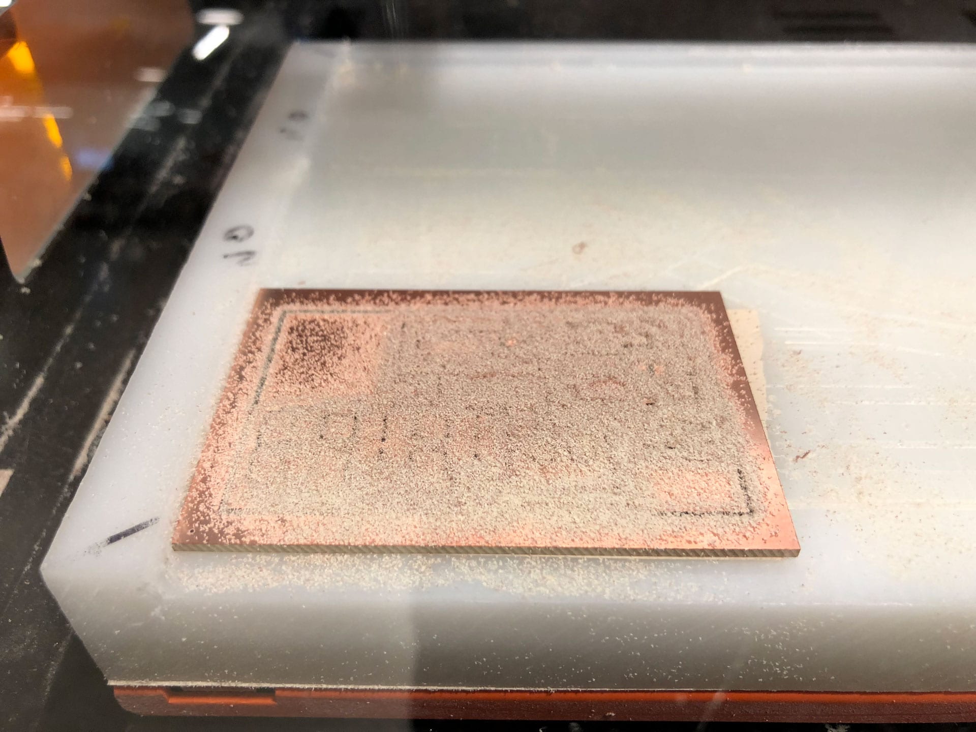
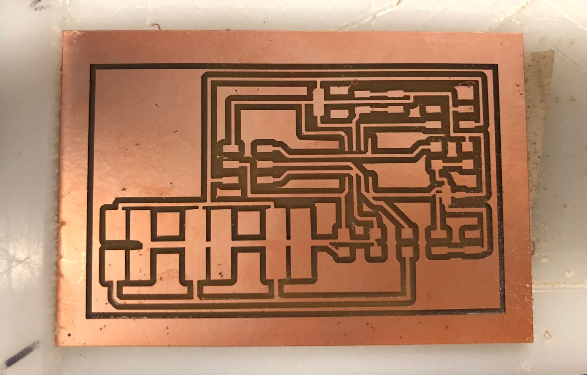
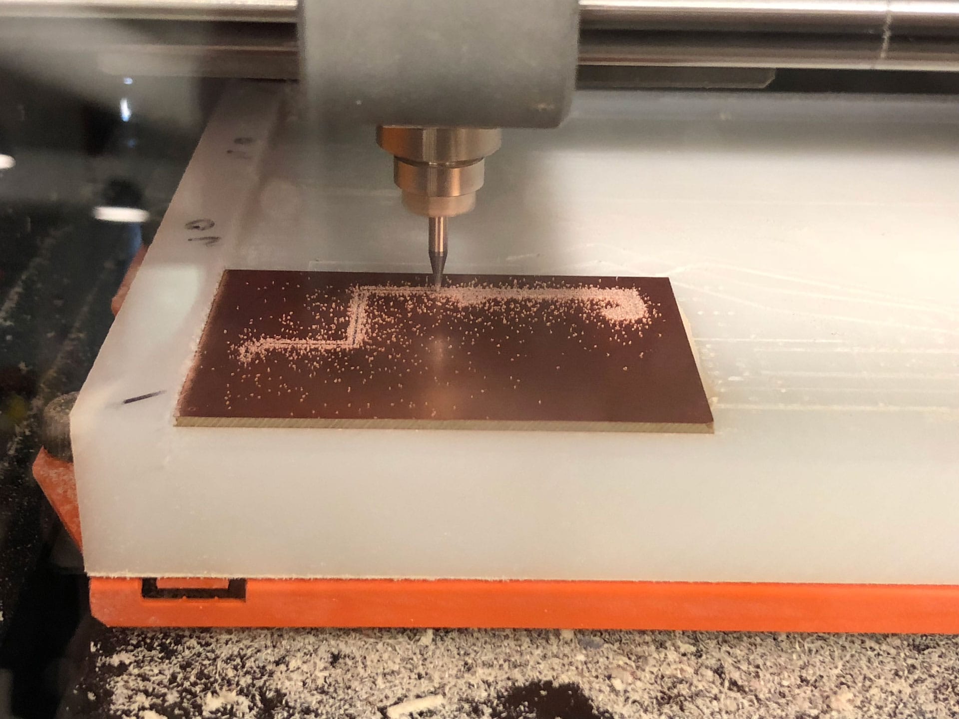
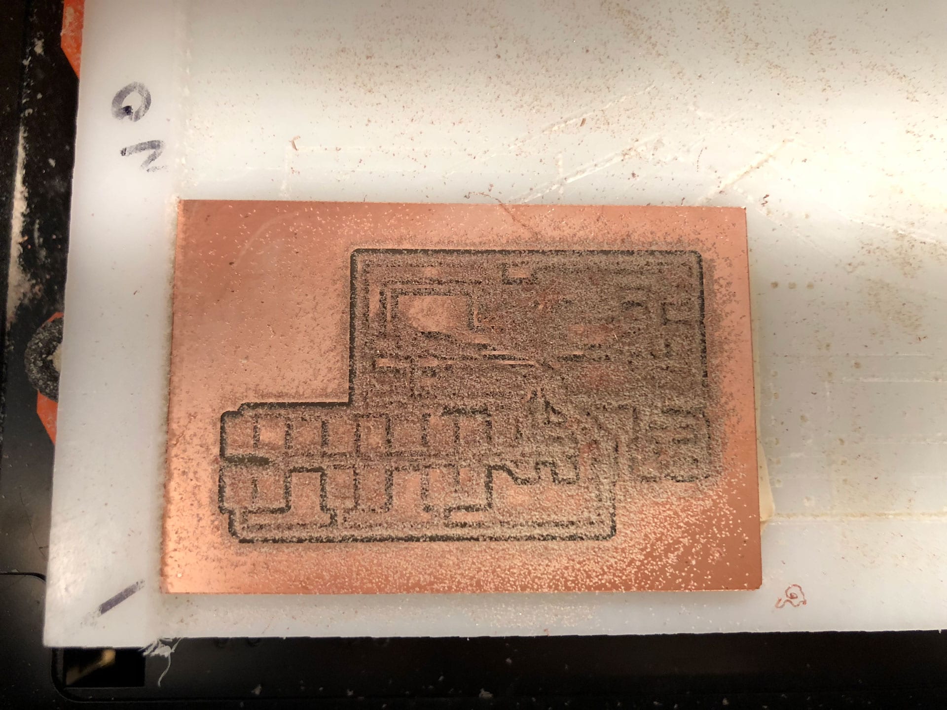
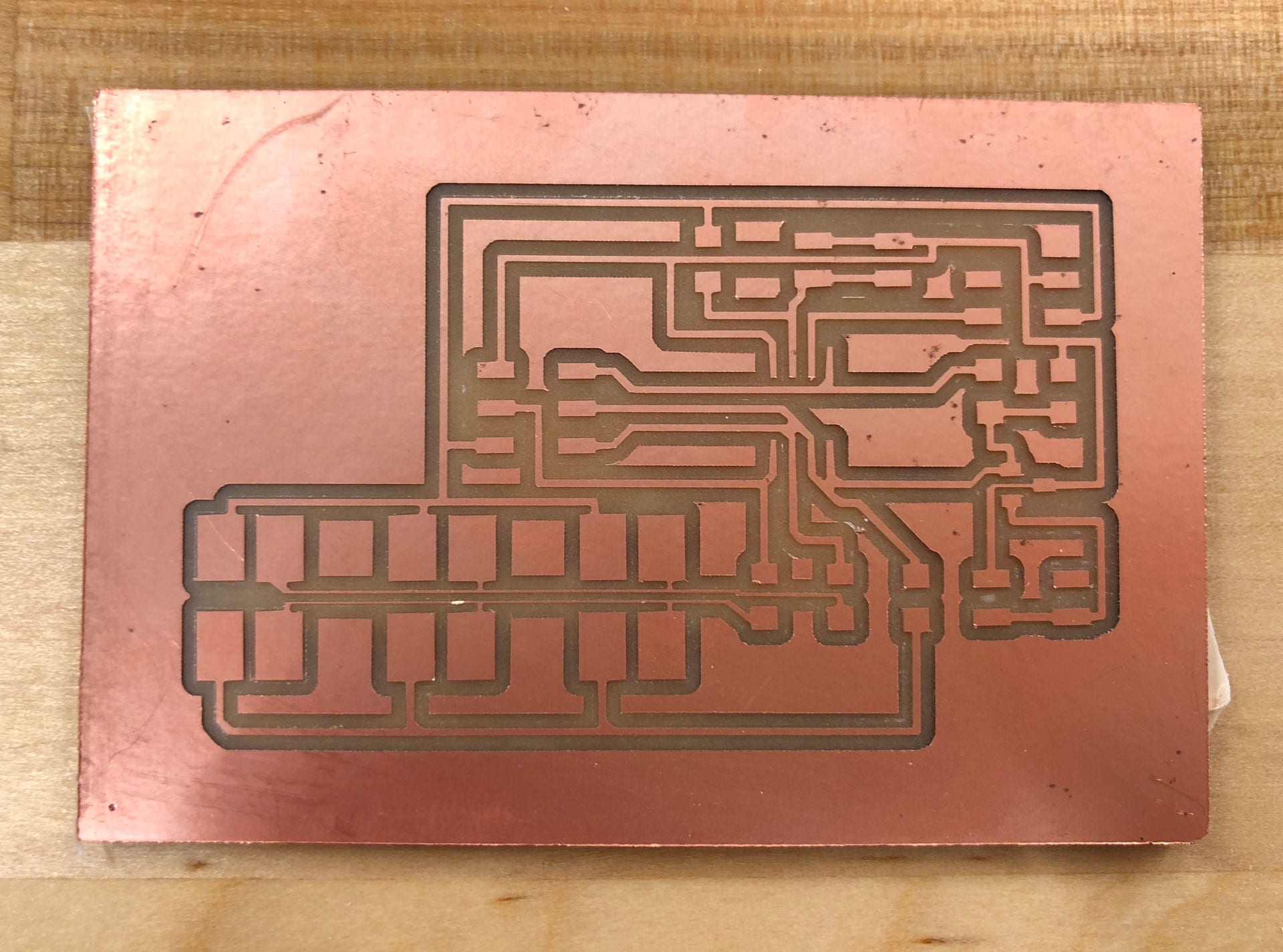
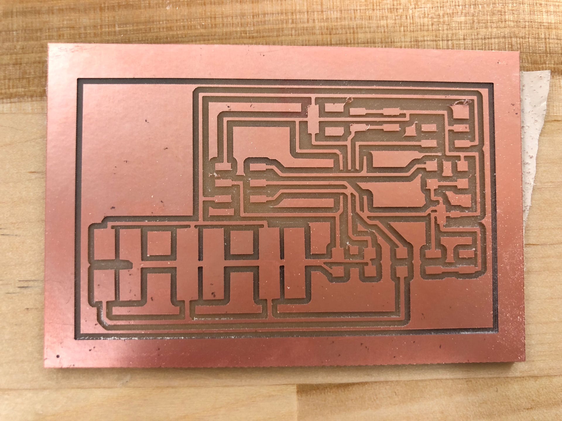
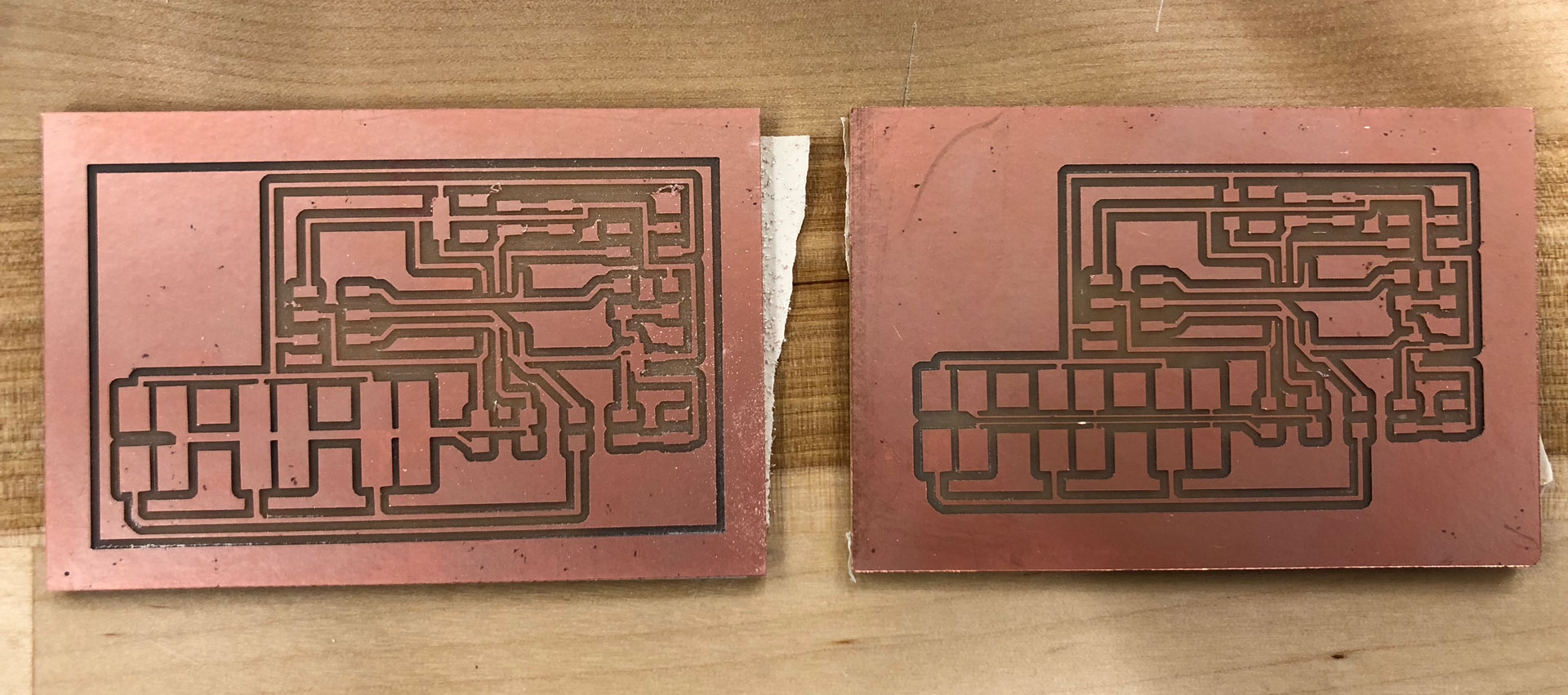
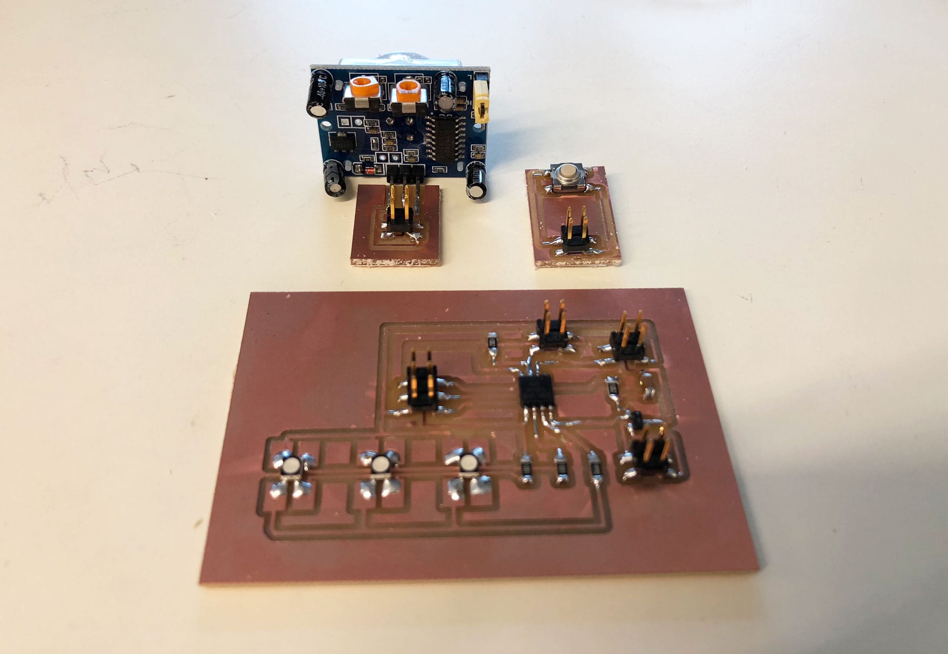
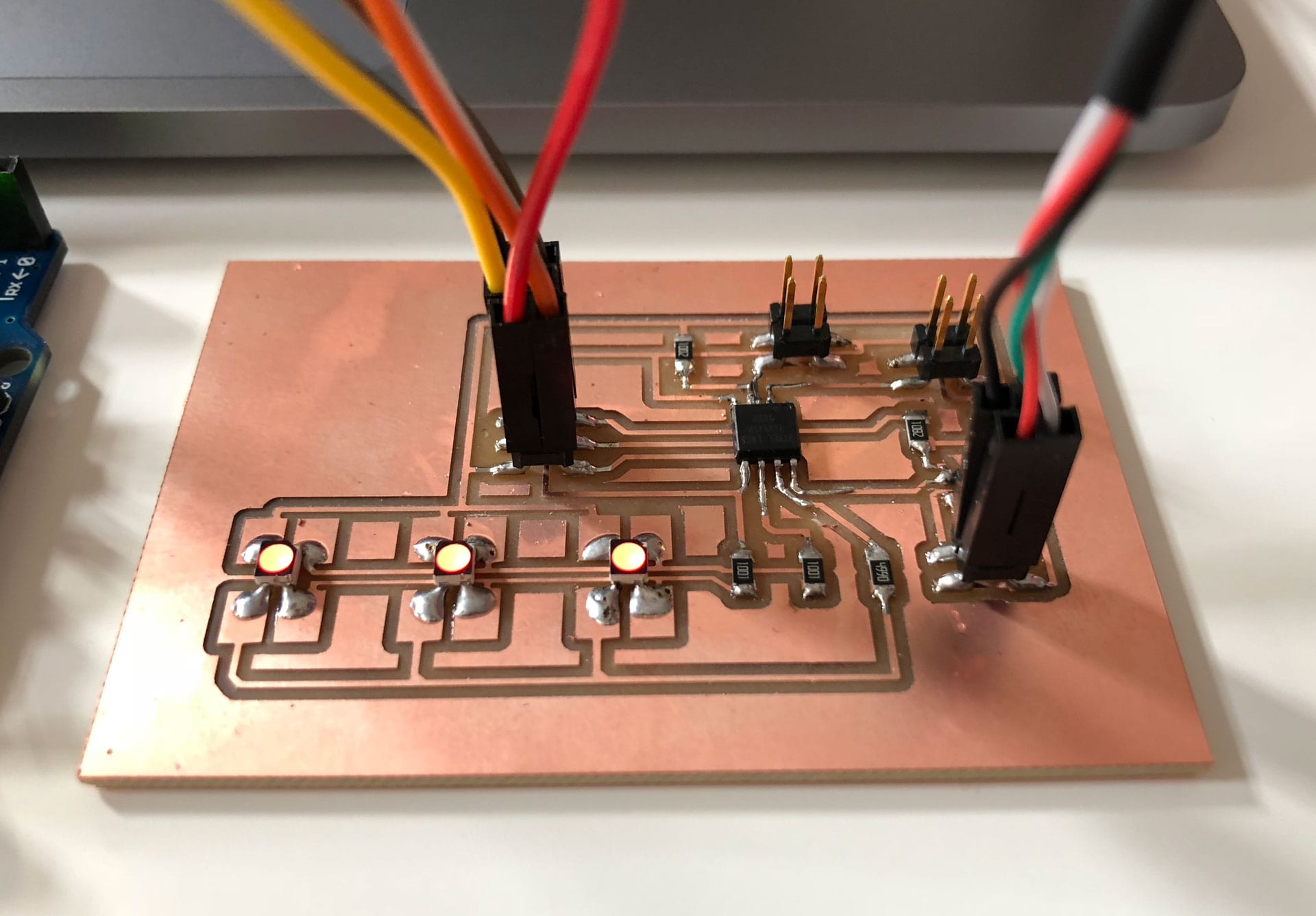
I then milled the sensor boards. These were fairly straightforward. I decided to re-mill the main board one last time to see if I could achieve thicker traces. I modified the pads and traces once more and this one proved to be the best iteration. I had to use an Xacto blade to cut a few joined traces, but otherwise I was happy with the board.
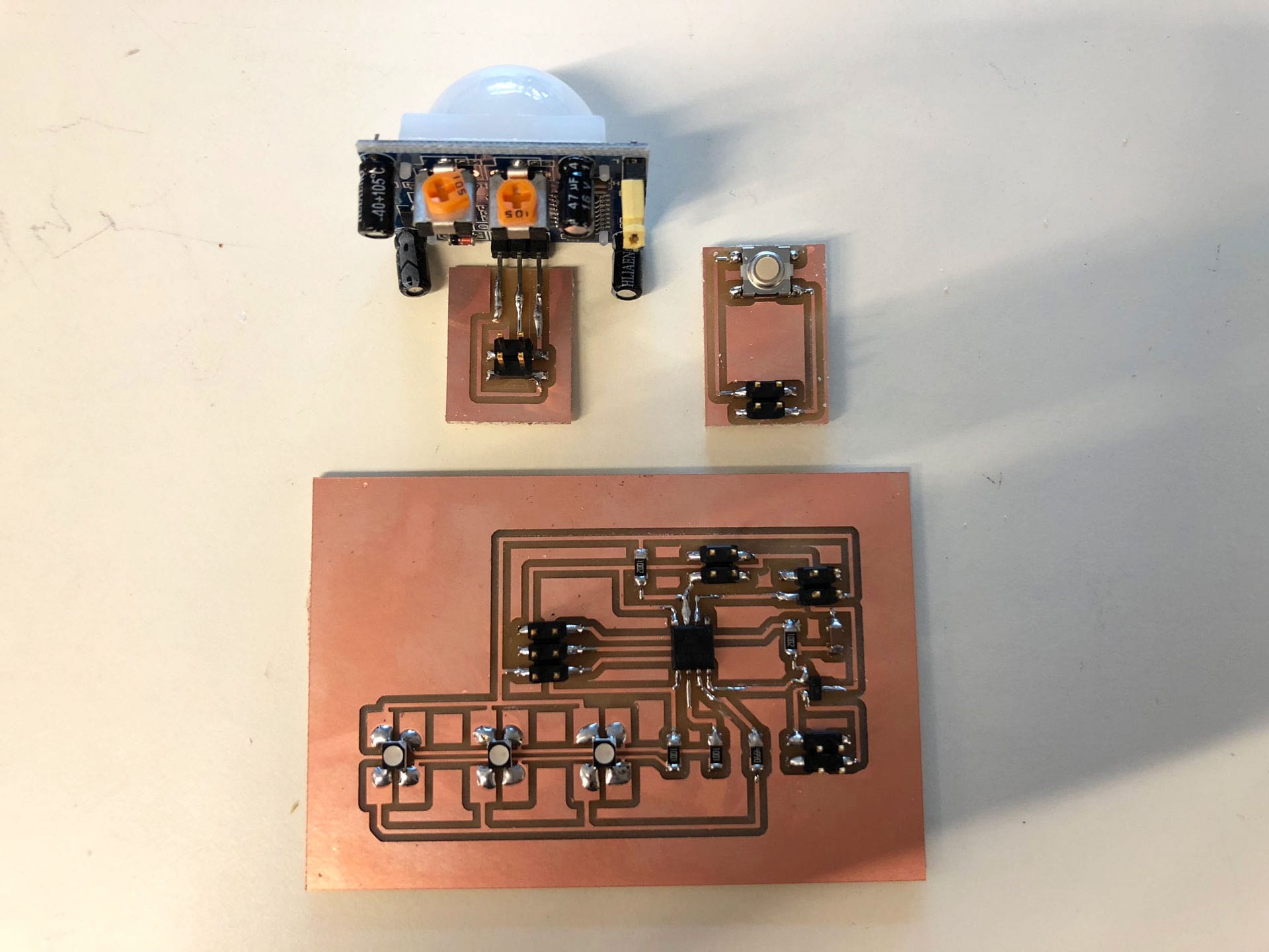
Assembling
The next part was assembling the components onto my board. I’ve improved my soldering skills quite a bit since the start of this class, and assembling the 3 boards took 25% of the time it took me to mill my first board which I was happy about.
Programming
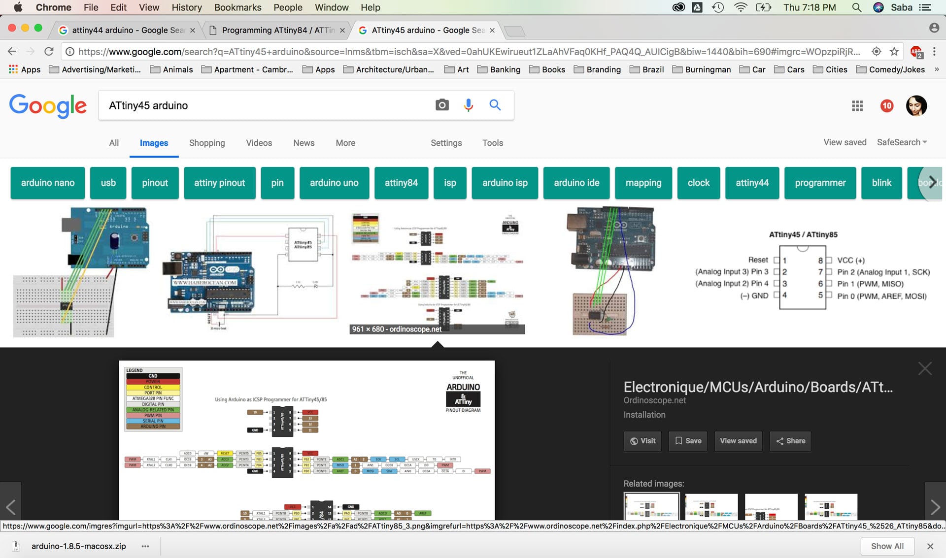
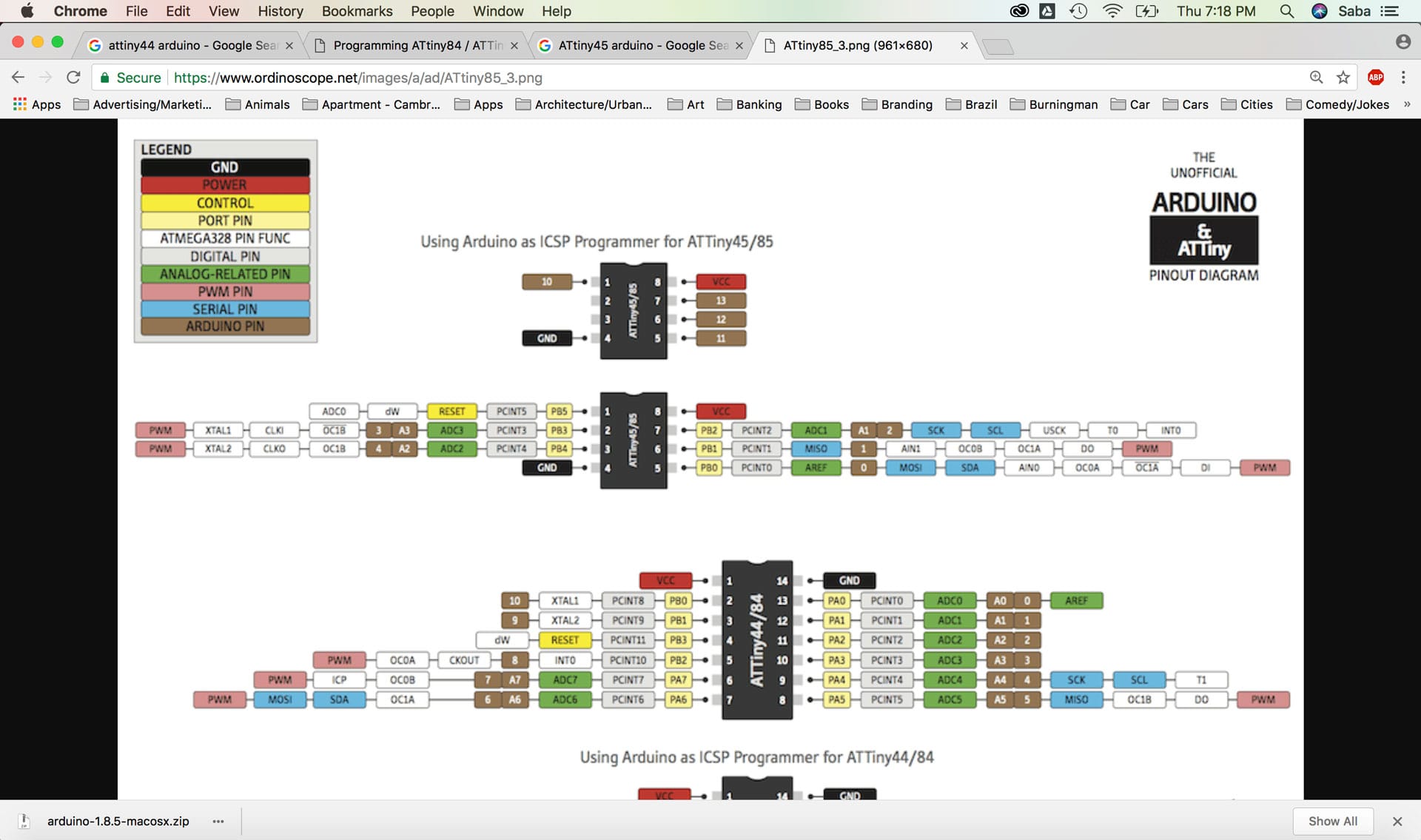
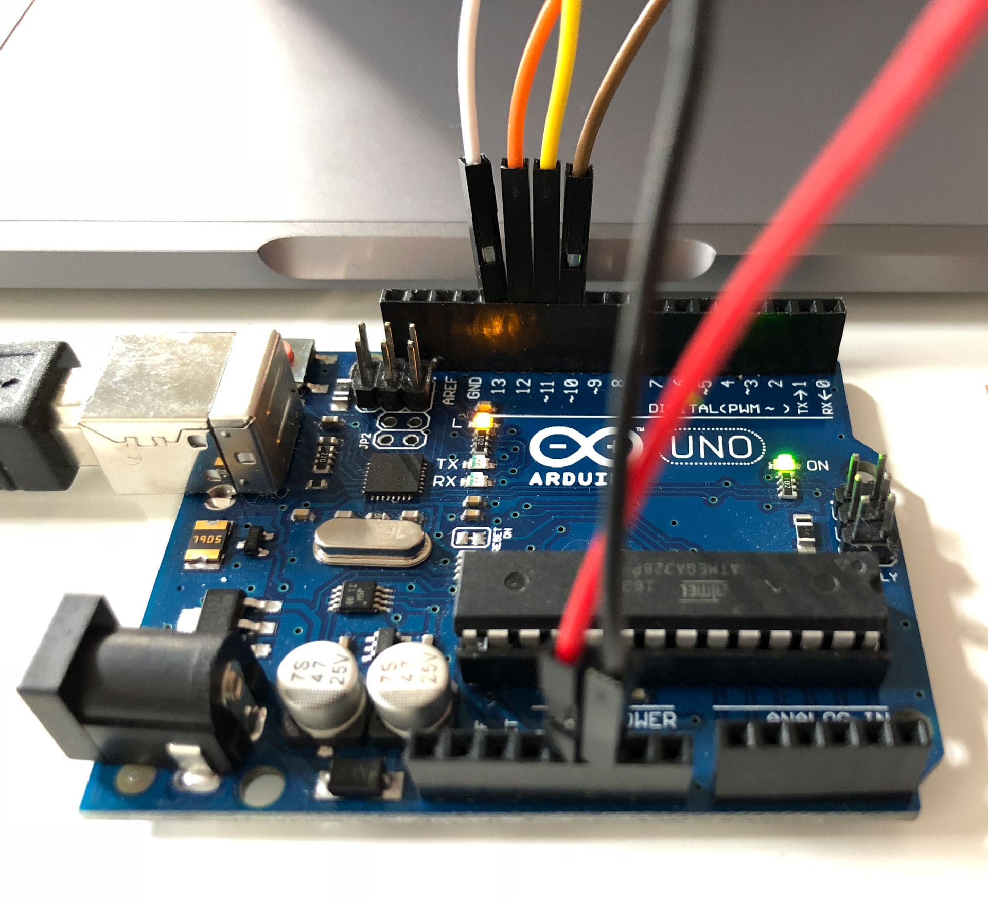
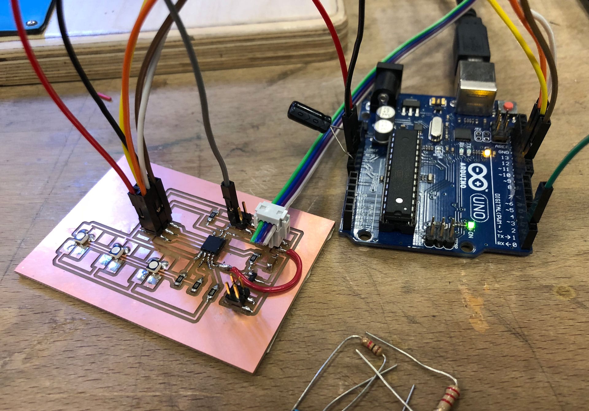
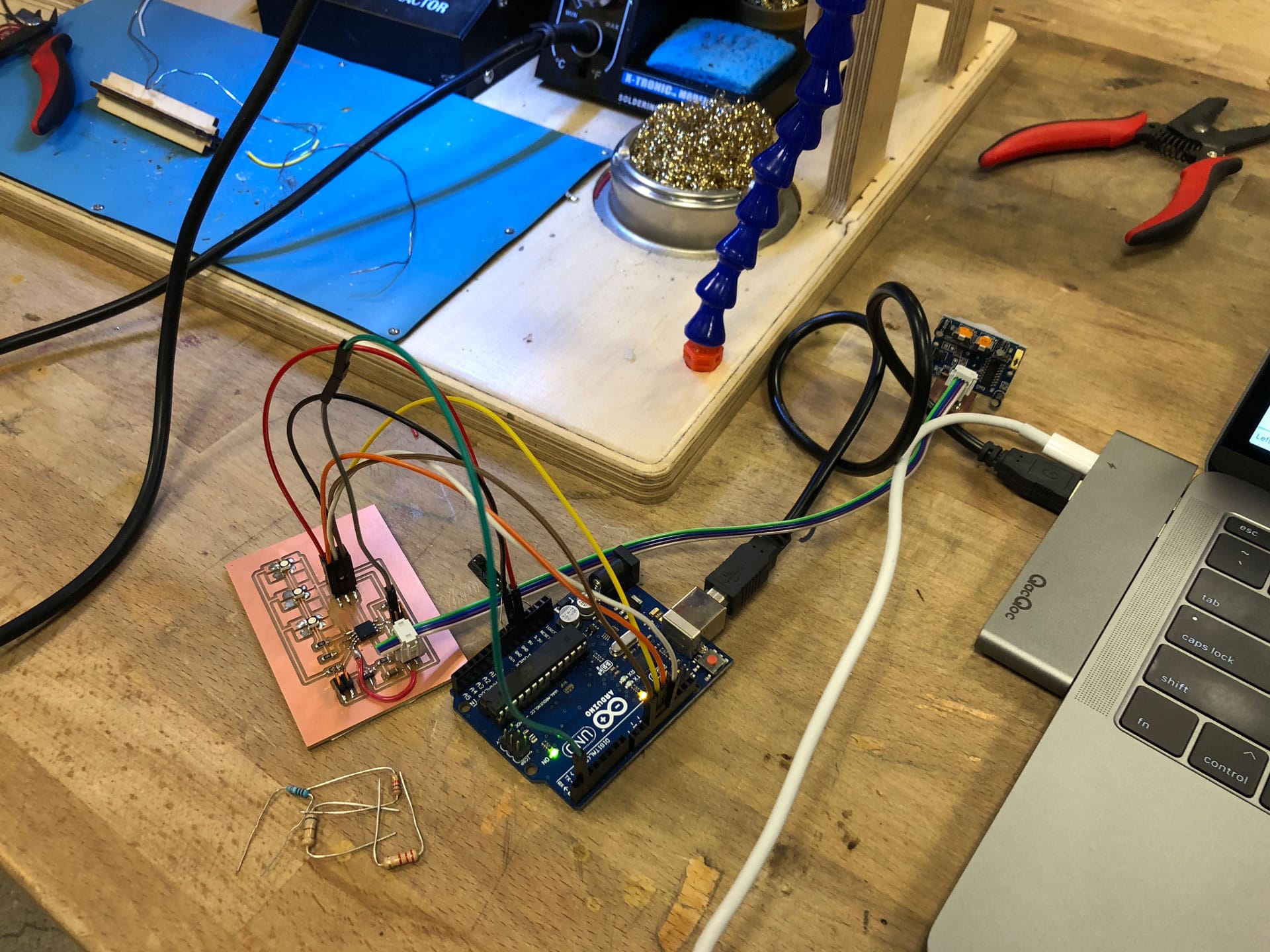
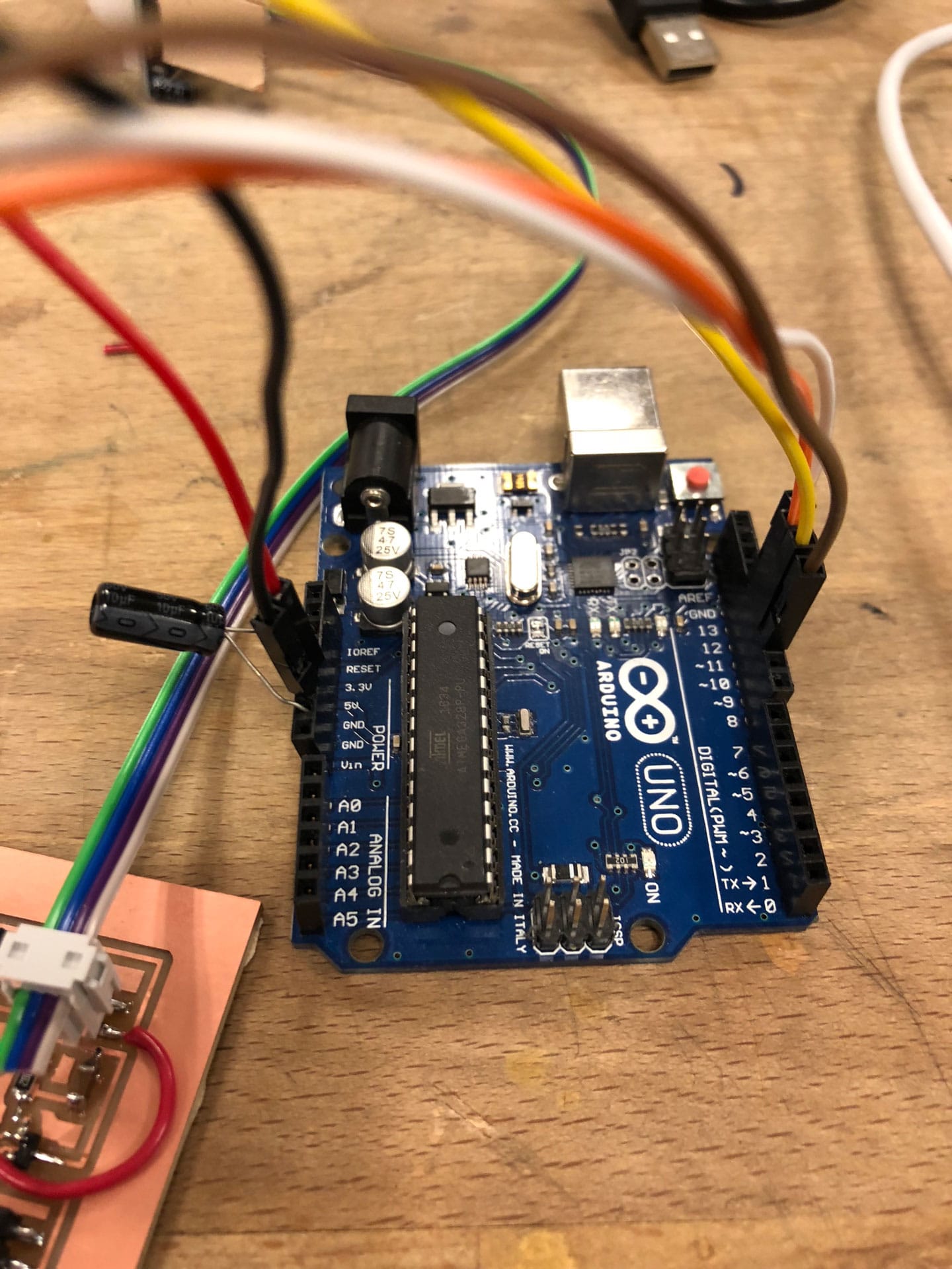
The final part was programming my board for both input and output. I first found the mapping diagram for the ATtiny45 to Arduino pins. I used the Arduino IDE and Arduino as ISP to program my board. Unfortunately, my first try at burning the bootloader onto my new board failed.
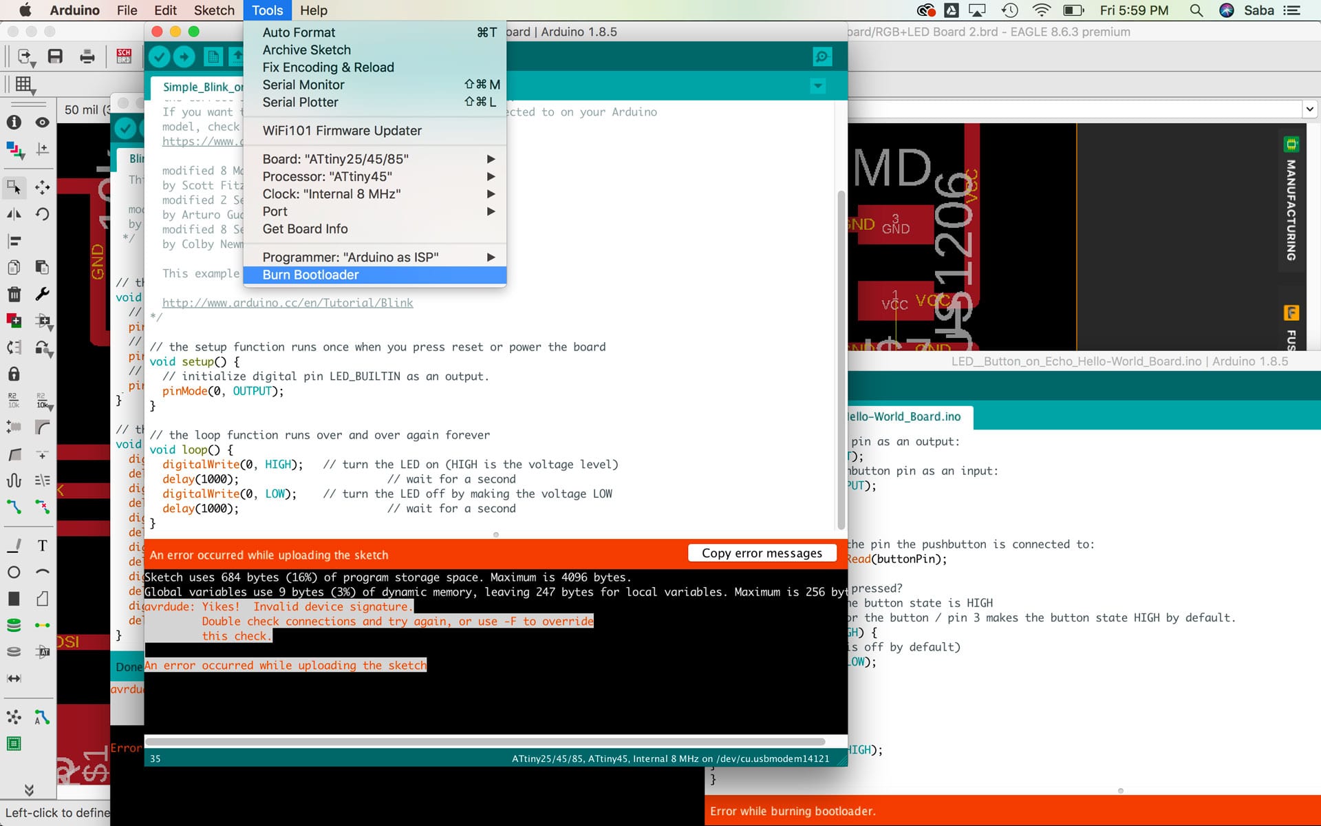
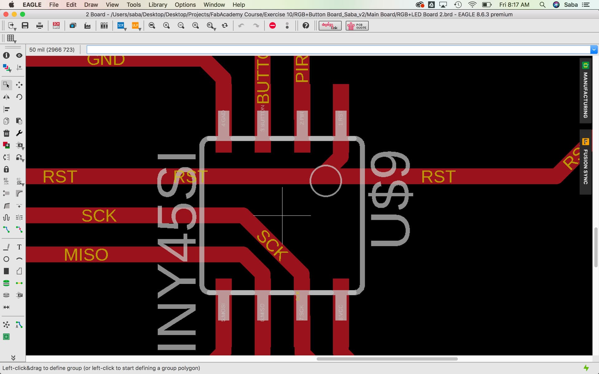
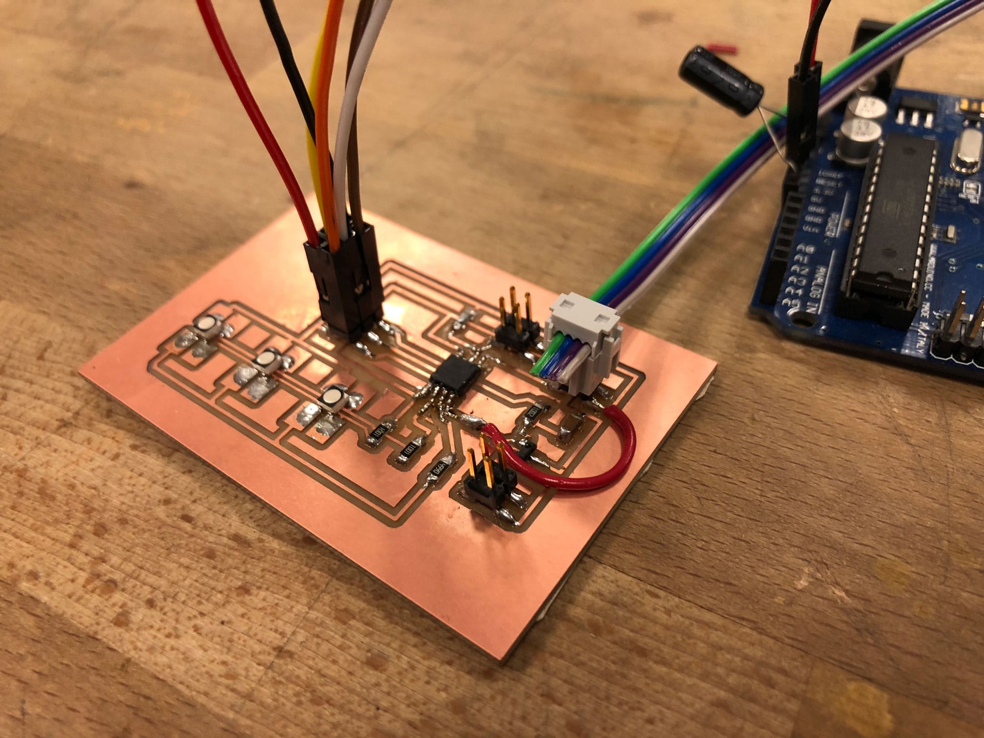
I began to troubleshoot, and after hours discovered 2 vital errors. The first error was a lack of connection between my VCC pin on the ISP header and my PIR sensor header VCC out. I soldering a wire connection between the traces (this was shown as an error on my eagle schematic that I overlooked). The second issue was a milling issue, where two traces were being connected when they should not have been, leading to a short. I searched for a long time until I discovered that the issue was directly under my microcontroller chip! I was able to use my documentation to verify this before I did surgery on the microcontroller to undo one side of solder and Xacto blade the connection apart. After fixing these issues, I was able to burn the bootloader!


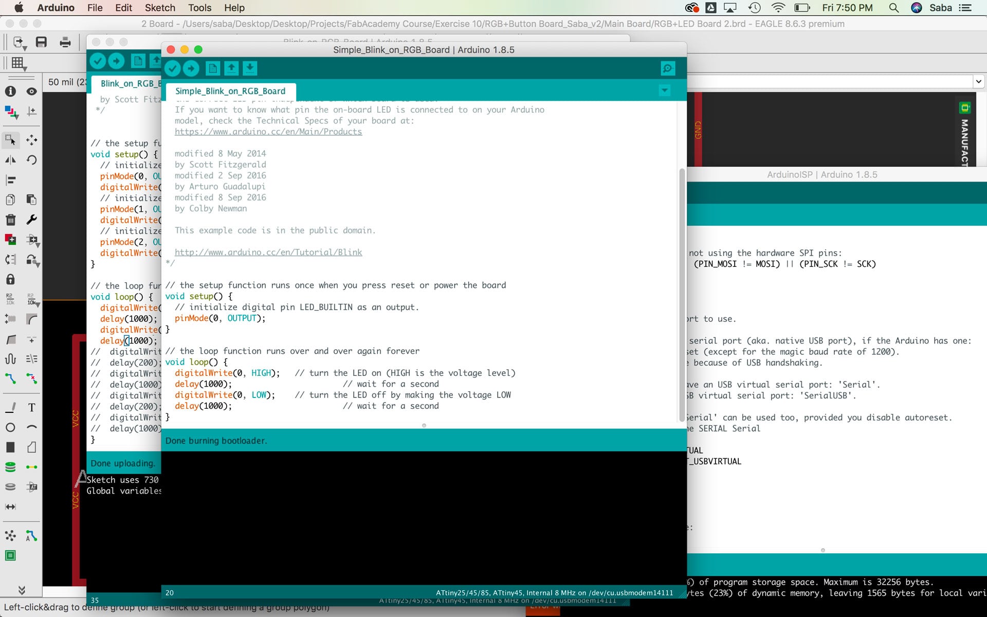
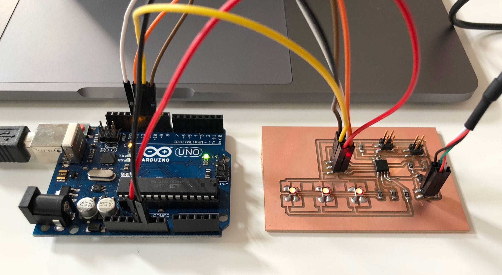
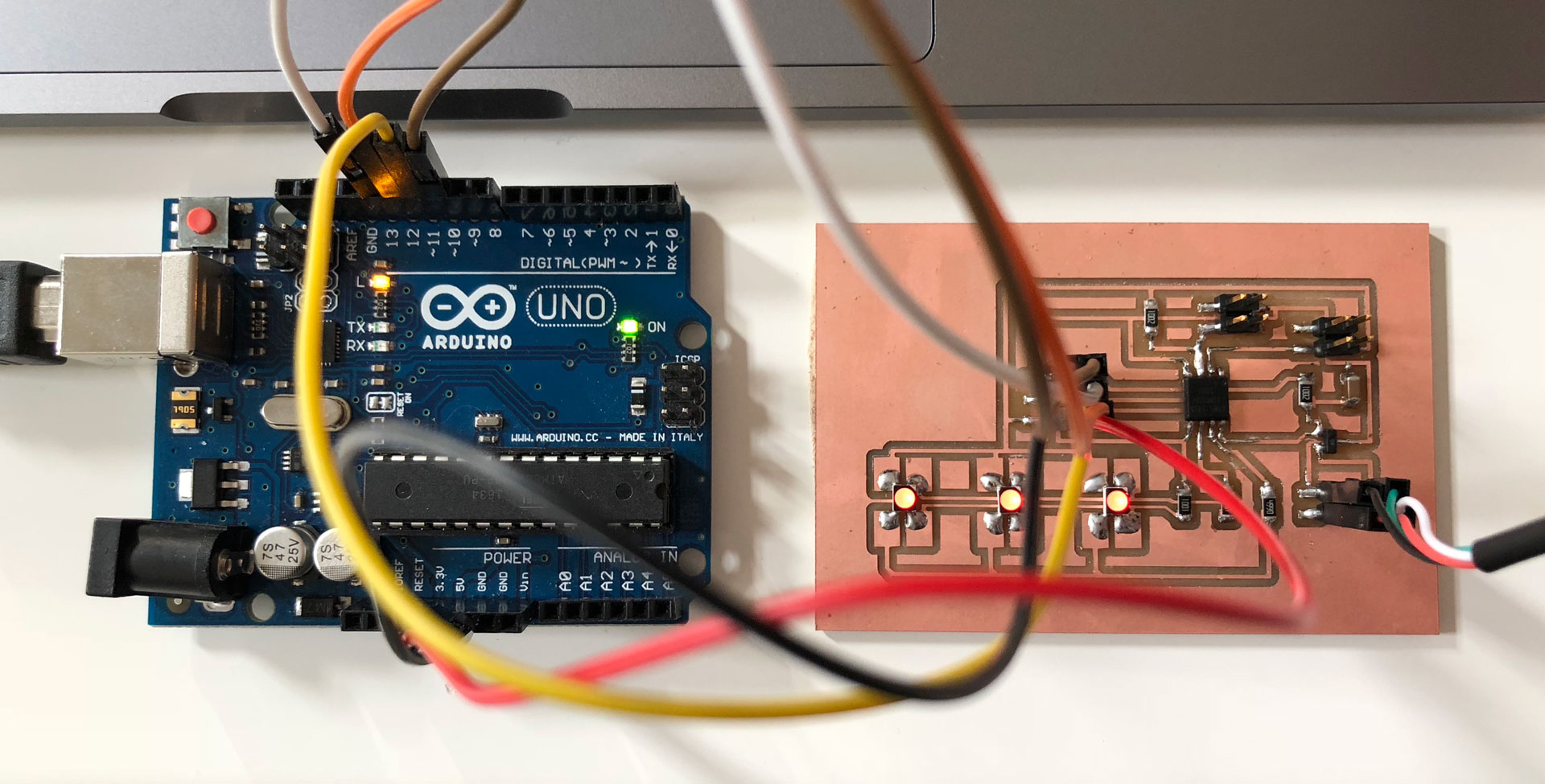
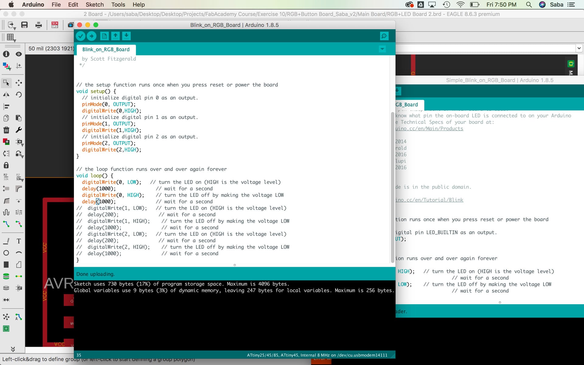
I then wrote a program to blink the 3 LEDs on my board, and it worked great. I noticed that the color of the blue mode for the LED was not quite right and tested a few registers to see if something was wrong with my resistor selection. I finally came to the conclusion that it was likely an error of having burned out one of the LEDs.

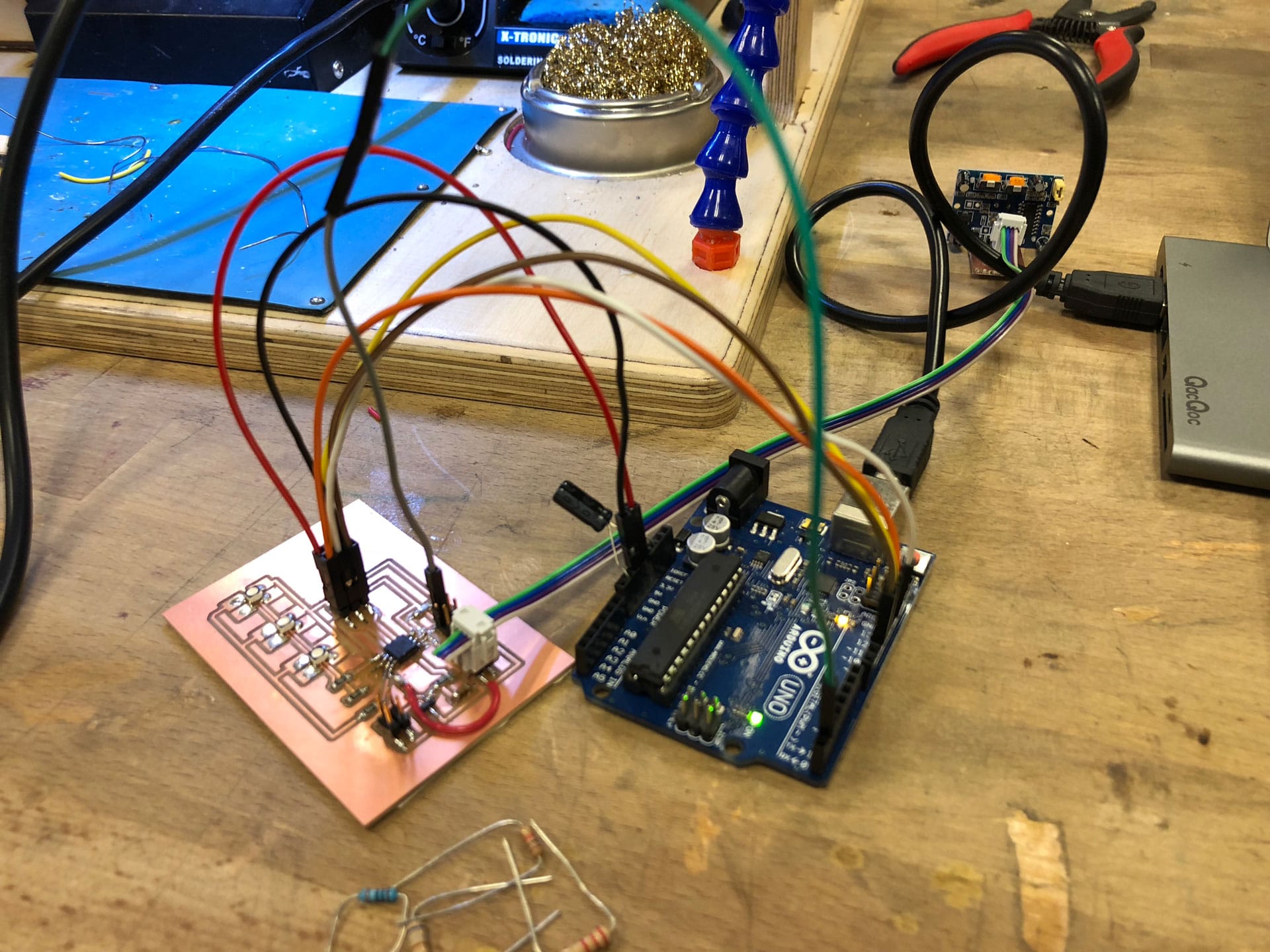
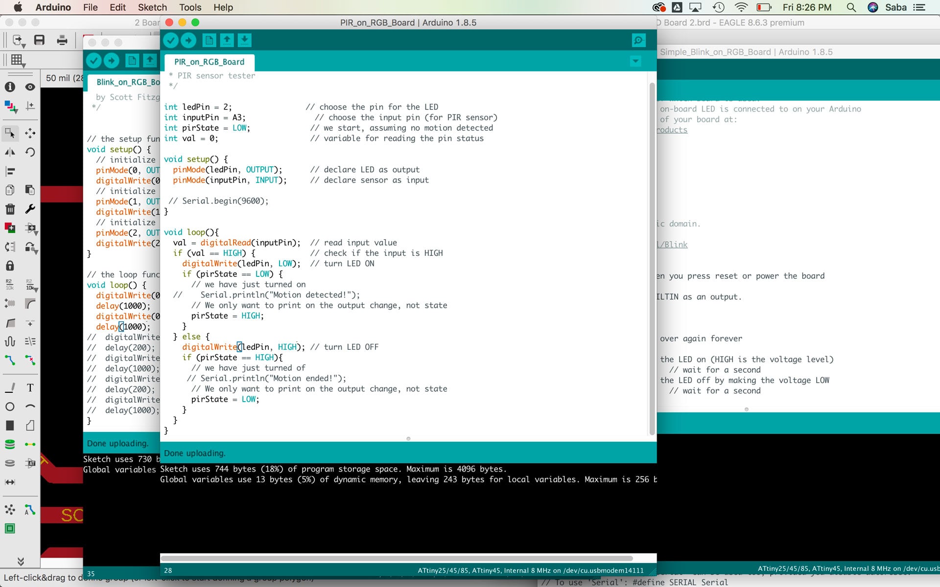
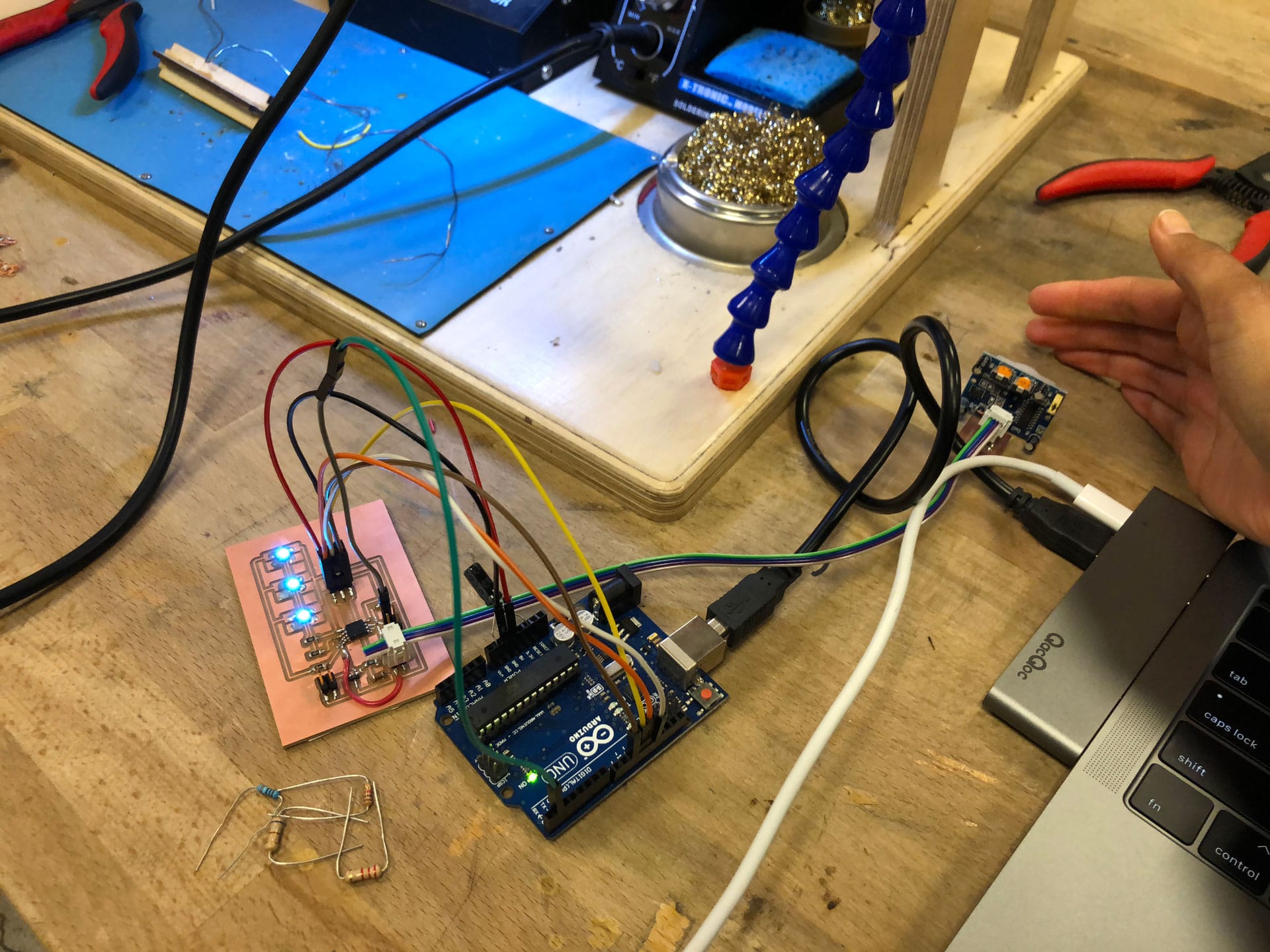
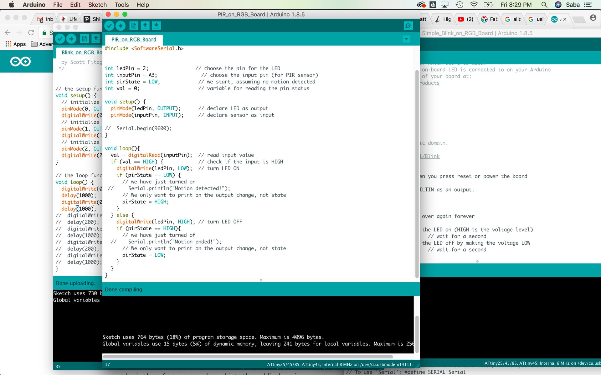
I then created a program to have the LEDs turn on when the PIR sensor detects movement. This worked great.
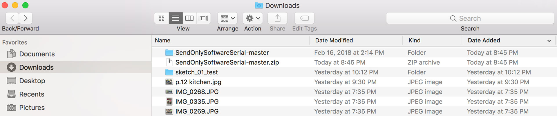
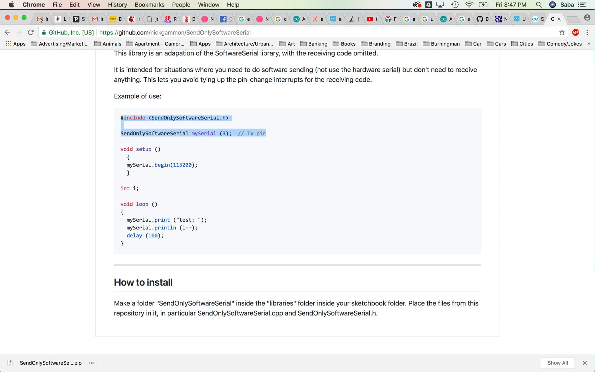
I tried to be able to get data from the Serial Port to read in the Arduino IDE, but couldn’t get this to work. Since I have only one Tx pin available on my board, I found a Send Only Software Serial library online and tried to use this, but it still didn’t work. This is something I will have to return back to to troubleshoot.
Programming Continued
:: May 1, 2018 ::
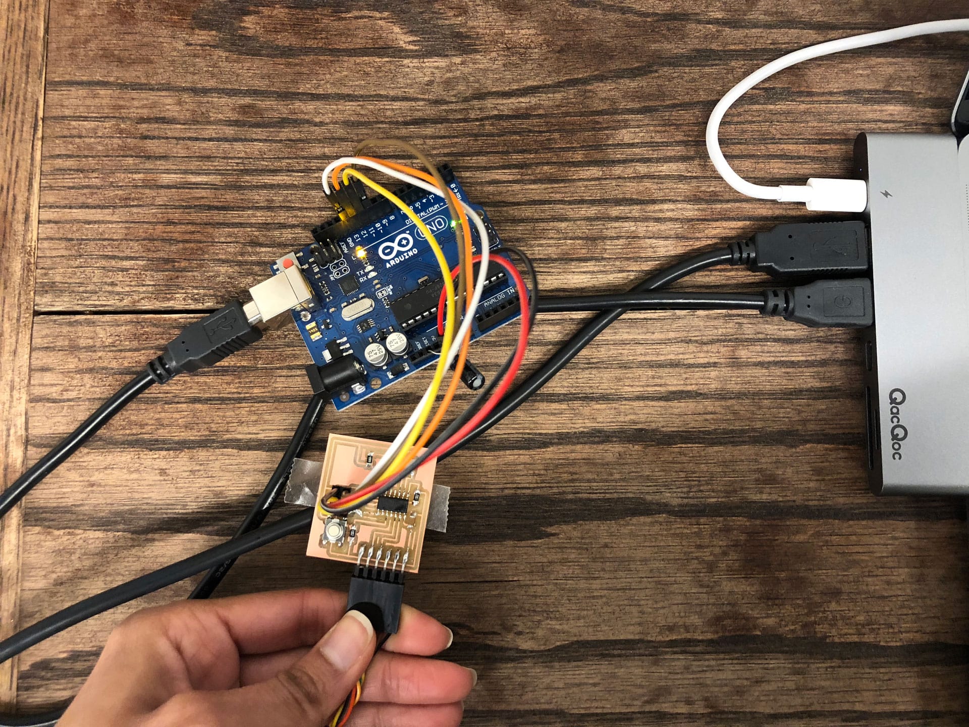
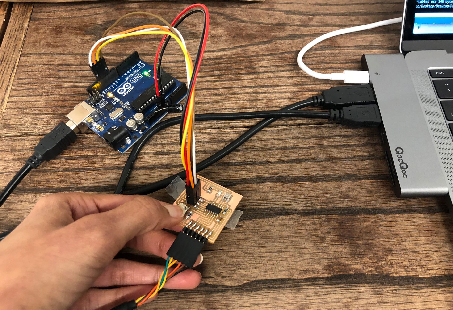
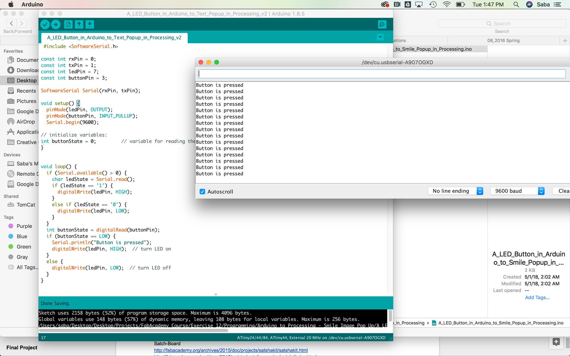
Here’s an exciting update. I finally found success in programming my LED-Button Board using my serial monitor. This is something that I have been trying to achieve for the last 2 weeks, unsuccessfully, and I finally got it to work!
I wanted to use my LED-Button board and serial communication and created a program to do just this. The Arduino program consists of declaring the values for the pins that will be used (rx and tx pins for the serial communication and then the pins of the LED and button). The LED is an output and the button is an input. The loop portion of the code allows for receiving of data through serial communication. It will also check on the state of the LED. If the LED’s state is equal to 1 it will set the LED to high, otherwise it will set it to low. When the button is pressed, a message will be sent to the serial “Button is pressed.” So when the button is pressed on my board, this action lights up the LED on my board and my serial monitor states “Button is pressed.” There were a few issues in this process that I finally was able to troubleshoot. I was using Arduino as an ISP. The first major issue was that I was using the port connected to my Arduino after uploading my code. I needed to use the port connecting to my LED-Button Board for my serial monitor. So once I uploaded the code, I needed to switch the port from the “usbmodem-XXX (Arduino)” port to the “usbserial-XXX” that was connected to my LED-Button Board. The second issue was that I had the Rx & Tx pins reversed in my code. The pins were configured to the setup of my micro controller, however, in this scenario, the two pins needed be reversed (Rx is pin 0, and Tx is pin 1) given that my serial monitor is doing the opposite: receiving the data transmitted from my board and transmitting data for my board to receive. Once I had corrected these two major errors, my serial monitor was showing the button state when pressed.
Resources
Here are some of the resources that were helpful for me.
Download the Eagles files for RGB+LED Board, PIR Sensor Board, Button Board, Traces, Outlines, and Arduino “Blink_on_RGB_Board” sketch.
Click to download Eagle .sch file.
Click to download Eagle .brd file.
Click to download Main LED+Button Board Traces .png file.
Click to download Main LED+Button Board Outline .png file.
Click to download PIR Sensor Board Traces .png file.
Click to download PIR Sensor Board Outline .png file.
Click to download Button Board Traces .png file.