

Project Development
This week is about developing final project and to use your previous work and learning skills of past week in your project , here i am using laser cutting , 3d printing ,electronics production , embedded programing , vinyl cutting , interface and application in my final project
I am starting by answering few questions related to progress of project development
What tasks have been completed, and what tasks remain?
Task completed
1 Project ideation - It was done in week 1
2 Electronics production - 1 Circuit Design
2 Electronics production- milling and soldering
3 Programing , interface and communication - communicating board with mobile application
using bluetooth
3 Frame development - Development of omni wheel
1 Omni wheel made of laser cutting and 3d printing
- cad designing
- laser cutting and 3d printing
2 Omni wheel made by 3d printing only
- Development of chassis including casing for electronics circuit
- Cad designing ,laser cutting and assembly of chassis , vinyl cutting
- Development of end factor
- Design 1 , Designing and laser cutting of end factor attachment 1
-Design 2 , esigning and laser cutting of end factor attachment 2
this things are arrange in order of there development with time
Task pending
1 developing more end factors for omni bot - done in end of the week
2 Making app for controlling bot - currently i am using open-source app for controlling bot - done in the end of week
status- this task are completed sucessfully
Deadline and reaming time
deadline for completing the work is 11 june for pushing weekly work including project development , and for final project we have to submit by 15 ,i have 3-4 days remain for completing my pending task
How will i complete remaing task in time
AS i have figure out the new designs for end factor attachment just because of limited time i was unable to compete that so i will complete that task in 2-3 days and for mobile application i am making app using mit app inventor which i have done in previous week but still need to figure out its motion properly
What was worked what not
things regarding movement of bot ,omni wheel are moving fine , attachemnt for fixing motor , battery , circuit is properly figure out and implemented attaching cleaning end factor on bot work but making universal end factor for bot is still not achieved
What question still need to answered
question regarding movement of bot in any direction using mobile app still need to answerd as i have only figure out geometry and programming of bot require for x-y movement for mobile app
What i learn
The most important aspect I have learned is system integration as i understand how you can use different digital fabrication to make one complete product
Files for final project
2 png files of final board for milling
3 Motor driving shield eagle files
4 Png files for motor driving shield for milling
6 Omni wheel roller file design 1
7 Laser cutting file for wheel hub
8 3d printed omni wheel stl and gx file
10 Chassis design with motor holder
13 End factor attachment design
14 Clip design
Project Ideation
Project Ideation was Planed in week 1 and some modification in design are done in coming weeks ,
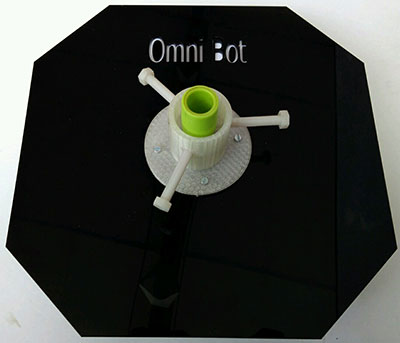
Project Idea is of omni bot , Which is a host bot with multiple end factor end factors attachment holder having utilities in floor cleaning and lot more as per user need, you can use it with some modification for random drawing on surface and lot more , Refer my week 1 assignment and week 18 for more details about its features and
Electronics production
Omni bot have two electronics boards one is modified shashakit board and another is motor driving shied with power supply , this is design with keeping functionality of omni bot require and future scope of development in this board as using moduler circuit you can add more functions to bot
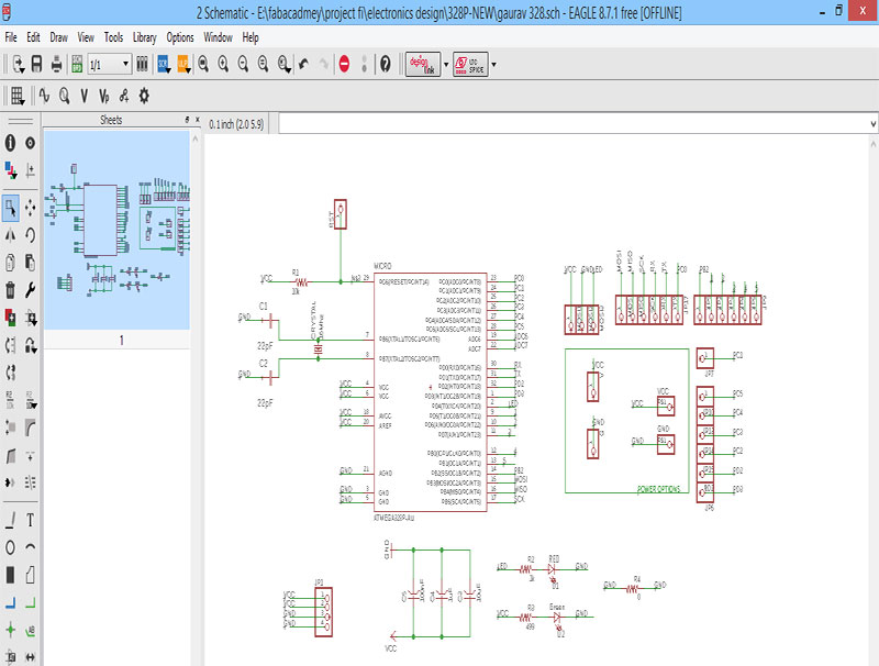
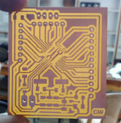
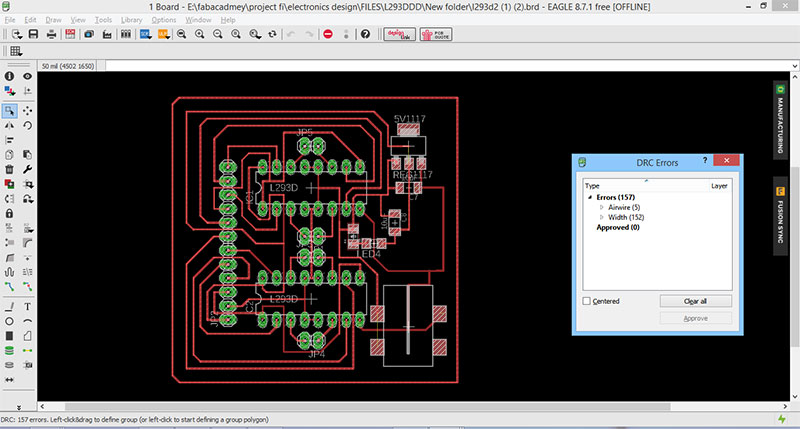
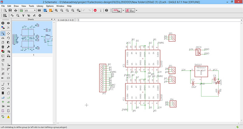
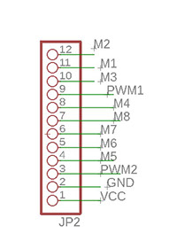
Eagle design of final board
This is schematic of my final board in this i have given 12 pin strip in one side to connect with 12 pins of the shield in which 8 pins are for motor connection and two pwm pins and 2 pins are for vcc and ground and i have given 4 pins for connecting bluetooth on serial pins and give jumper on remaining input output Arduino pins which i can be use in case when i need to attach any sensor or any output device to it ,as i want to make it moduler so can be used for any other purpose so i made motor driving shield separetely than board .
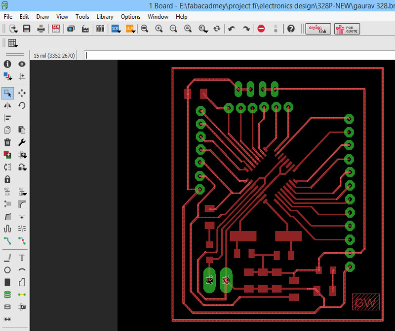
final board design
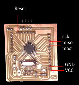
Connection diagram for Programing this board
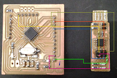
for programing any board you need this pins i have attach female jumper on this pin you can connect fabisp with this pins to program the board
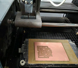
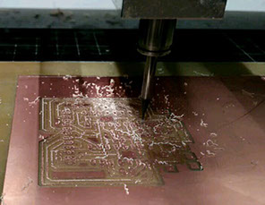
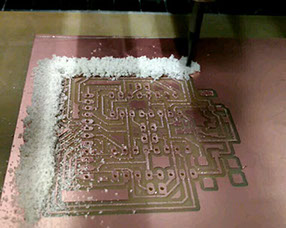
Milling Process
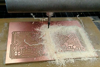
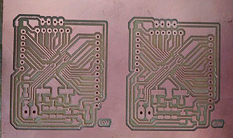
I milled two board together as i have enough space left on my pcb board and i want to utilize it properly , you can also do this if you are sure that your two board fits in one board
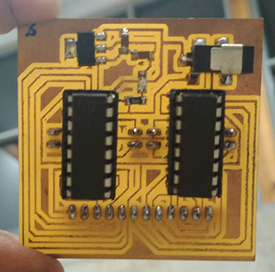
Soldering Process
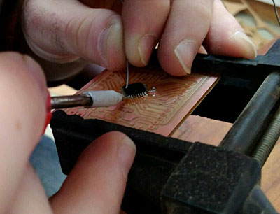
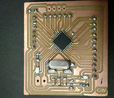
soldering the board you need to take care more about soldering ic of board
Designing shield for final board
For designing the shield i used 2 l293d IC for pins of which connect to 12 pin jumper which i fix on my final board and i gave lm117 as a voltage regulator and it convert 12v into 5v to supply power to my circuit and capacitors in its circuit , for 12 v power supply i gave dc jack and 2 pin jumper which is connected with lm117 circuit , i made similar circuit in week 11 using attiny 44 you may refer that also ,
Milling the shied board
Tracing board
Drilling Operation
Cutting Operation
You can get the png files for this in top
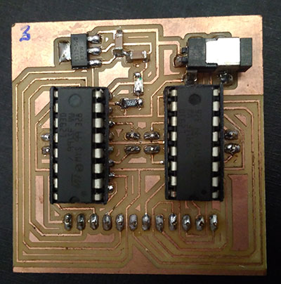
Here i am using pin hole l293d ic as smd ic is not avaliable in market and i can't procure it but you should use smd ic iwhile making this circuit
Connection between board and shield and bluetooth
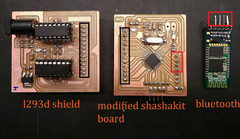
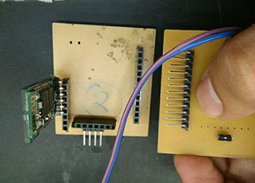
i used 3 things in my project the connection diagram for them are as follow
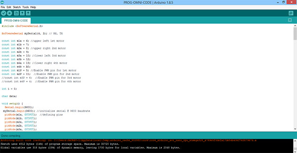
Programing Code and interfacing
Frame development
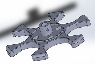
for development of frame major challenge for me is to figure out geametry for omni wheel as this are important part of my project for this i also design complete assembly of omni wheel in single part in week 6 , i can't use that assembly for my final project as in that my roller are moving on plastic rod and on loading it will break so i need some metal rod to hold my roller so i start designing wheel in assembly
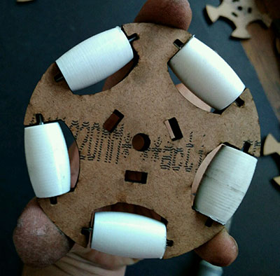
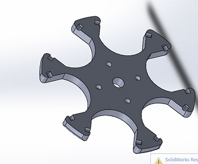
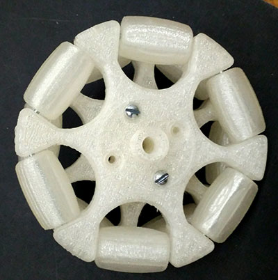
Omni wheel made of laser cutting and 3d printing design 1
this is the first prototype i made for using laser cutting hub and 3d printed roller
what is good about this
this wheel are made using laser cutting hub as this cost you less than fully 3d printed wheel and they are functional
Limitation of this wheel
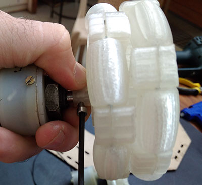
1 As it is difficult to fix motor on this wheel as motor slips on it without proper mounting for attaching motor so ihave not use tihis in final project
2 they are heavy than 3d printed wheel
3 you cannot give fillet on its edges so not smooth edges
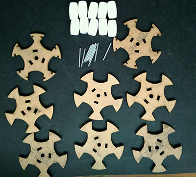
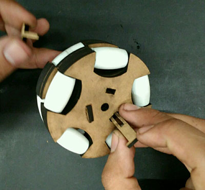
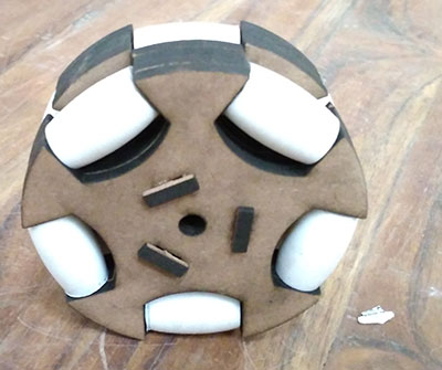
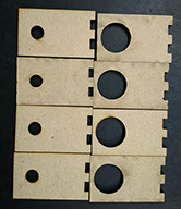
Process of development omni wheel
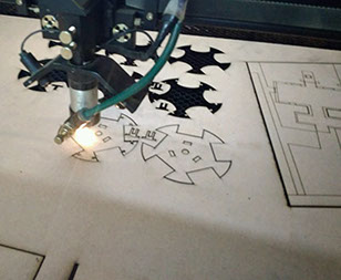
laser cutting hub parts and 3dprinting roller as ,I 3mm pieces which i join together using press fit laser cutting clip
Doing assembly of Wheel
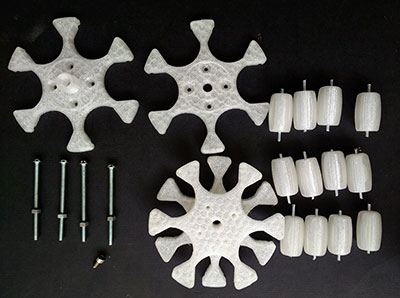
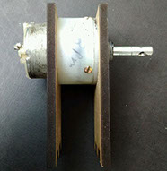
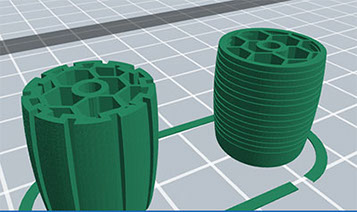
Making 3d printed omni wheel design 2
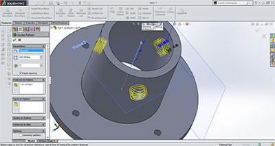
for making 3d printing omni wheel i decided to make that in 3 parts for which i design them first in solid-works and generate stl file to print this i printed using pla material and i finally use them in my final project as it overcome the limitation which i have in design 1
Desiging cad model of onmi wheel in solidworks
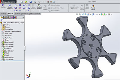
Left side part
Right side part
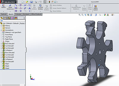
Cental Part
Back view of right side part
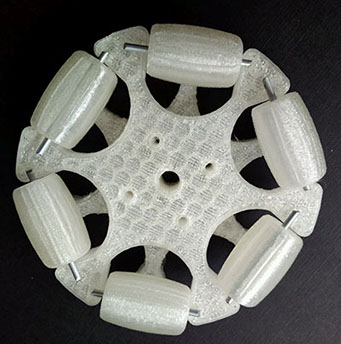
This is final design of omni wheel , it comes after 2-3 iteration in which i did dimension changes in size of hub and roller as i need the roller to touch the ground and hub periphery part to remain in air while moving than only my wheel move properly .
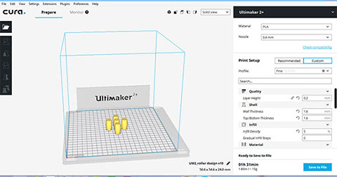
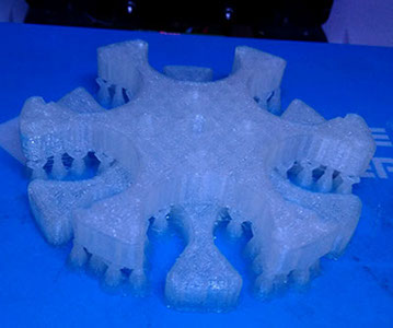
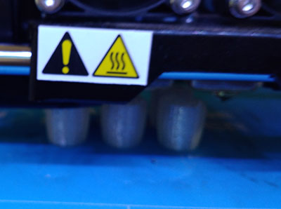
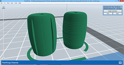
3d printing omni wheel
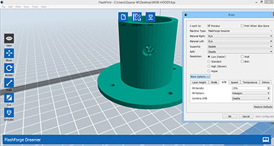
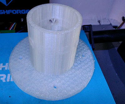
i printed the omni wheel in flash-forge dreamer 3d printer , i printed this in transparent color material as this is available in extra in our lab
Here are different print setting i used in printing wheel hub in flash-forge dreamer
Printing Wheel in flashforge dreamer
Assembling omni wheel
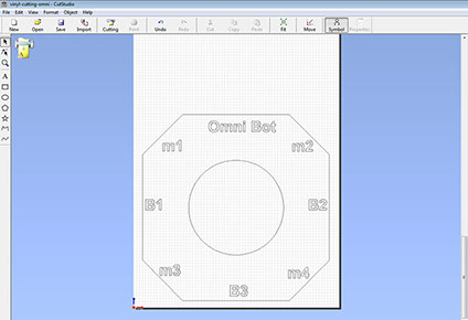
Designing chassis of the bot
for chasis desiging i made 3d design in week 3 start with designing in 3d cad model in solid-works so that i may get an idea of omni bot This i used for reference , as i am making this using using laser cutting so i start designing its 2d cad files
Things i design for my model of Chasis
1 Chassis with motor holder attachment so i can fix 4 motors on my chassis
2 Electronics circuit casing , i need to fix my electronics board to my chassis base so i made press fit box attached with my
chassis and have hole for wires etc
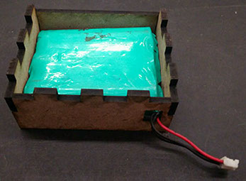
3 Battery casing - i need casing attached to my bot for this i made casing from which you can easily remove and add your battery to it
4 Attachment for holding mob - as i am using this bot for cleaning purpose so need attachment to chassis of my bot where i can attach cleaning attachments
i started designing each thing one by one and testing its fitting and finalizing it for final project as you can also adopt this approach of step by step development
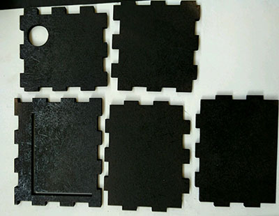
Designing chassis base with motor holder attachments
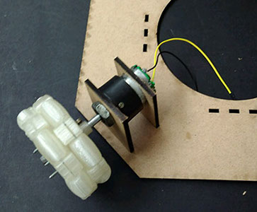
for the first phase of designing i just design motor holder attachment in chassis base as it need to figure out its geaometry and see that as press fitting is good for holding motor or not and yes it work for me i made press fitting attachment for holding motor in final chassis design
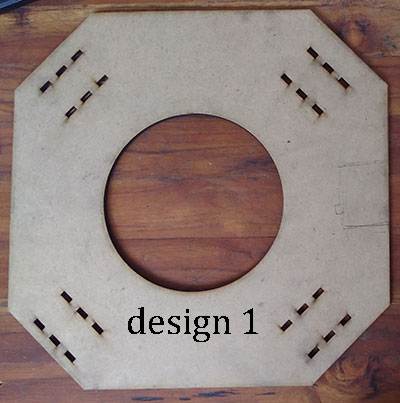
this is my first design of chais in this i have only given slits for fixing motor this is essential to find press fitting and i used 4.5 mm mdf sheet in this and you can tight nut to fix motor properly
Design 2
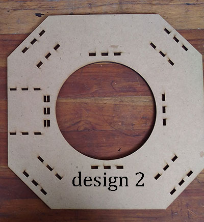
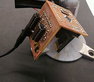
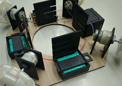
in design 2 ,i have designed slot for fixing electronics circuit
my circuit have 2 boards and one bluetoooth module and the are perpendicularly connected with jumper so design a box for to it permanentely fix it on base of chassis
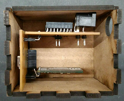
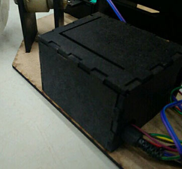
i used this in prototype 1 of my bot
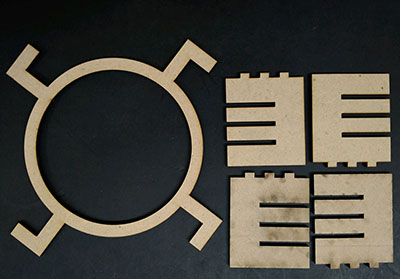
Designing attachment for fixing mob for this
what good about this design
1 this is good attachment as you can easily attach and remove mob
2 diffrent heights for setting mob
limitation of design
1 In this design the disc is coming out of slots
2 this is not strong enough
Modification in design for final bot
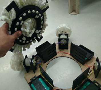
in this the disk have lock which is gona fix in one side thus avoide problem of disk coming out of slot and it is more tight you just need to move disk and take to wash it and fix again into it , in this picture you , here you see wires out which i fix in final model
Design 3
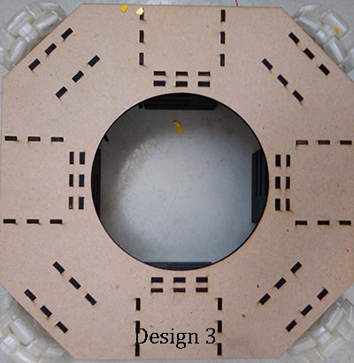
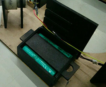
In design 3 i have give attachment for fixing battery holder as here and a sliding bar to close it and remove battery easily and design 3 is the final design of bot as this slider you can take out for removing battery
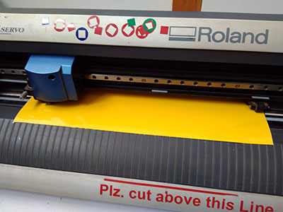
Vinyl cutting the top part
I want indication on top of my bot for motor M1,M2,M3,M4 and battery as B1,B2,B3 for this i design the vinyl cutting file , as i have created dxf format file for laser cutting ,
challenges in vinyl cutting
i used the same file and export it as jpg for vinyl cutting as i face a problem there that it will convert the single line into double line while extracting contour lines and they form ploy lines so difficult to delete one line so i made file in adobe illustartor than i reduce stroke size to export it than i get currect
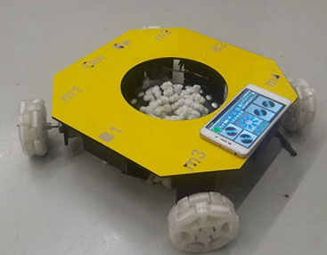
Prototype 1 Chassis top and bottom view / hero shot
Final Prototype development
Considering limitation of prototype 1 ,i decided to improve my bot to take it to next level in this
Things which work in prototype 1
1 Movement of wheel - as wheels are moving fine on floor but traction factor of wheel can be approved
2 motor attachment as in prototype 1 motor are fixed perfectely as i can use them for final prototpe
3 battery and electronics board casing work as my batteries fixed properly and electronics board also fits properly inside casing
Things need to be improved in prototype 1
1 end factor attachment in prototype 1 need to be improved considering strength and attachment fixing is not proper
as get me loosen up on moving bot
2 considering aesthetic look of bot need to be improve
Designing the end factor attachment for bot
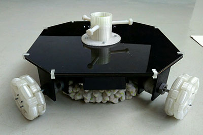
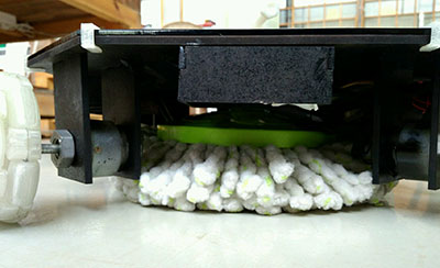
for designing the end factor of bot ,i need first the end factors which i am gonna fit in my bot as i bought 2 mob which can be fixed in my bot and easily available in local market so anyone who is using my bot for cleaning can use those attachment and replace them
Cad Designing of end factor and 3d printing the end factor
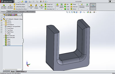
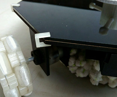
i design that model in solid-woks and print that using the flash forge dreamer printer also i attached it to acrylic sheet which i clamp on bot using 3d printed clamp and i used the prefabricated 8mm plastic screw in this which are available in our lab as per that screw as 3d printing screw will break along the layes so i used casted threaded screw
Improving Aesthetic look of bot
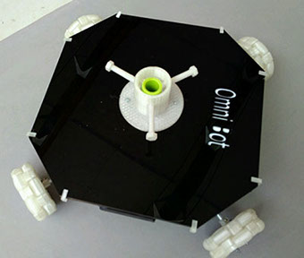
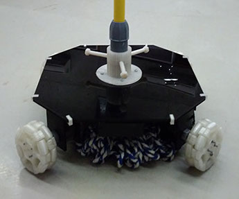
For improving aesthetic look of bot i attached an acrylic sheet on the top of bot and fix the end factor attachment on topand painted the bot black so it look cool
Hero shot of final bot
Developing App for controlling bot
In prototype 1 i am controlling bot using open source mobile application bluetooth rc controller through this app i got an idea of controlling bot and and in this app on pressing button it sends a character value as "F" for foward , "L" for moving the car on left side as this is code for rc car i need to write a program on basis of this character for omni bot for which i find very good reference on intractable i used that and modified that as per my requirement and i made my own app using that logic and did modification in programing code
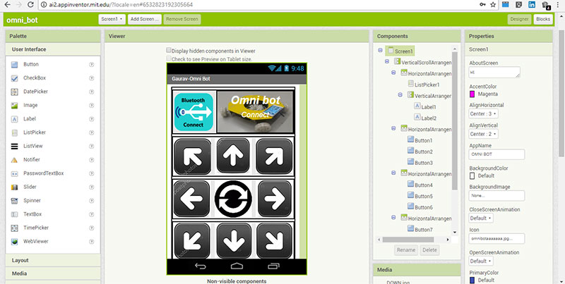
Developing App using MIT app inventor
As i have prior experience of making App in MIT App inventor in week 14 , so i design the final project app using the same software here i use press up and press down buttons for controlling bot with which when you press down the button it send character let say F and on press up it send another character s which is for stop everything else everything is same about making bluetooth application as i explained in week 14 and week 13
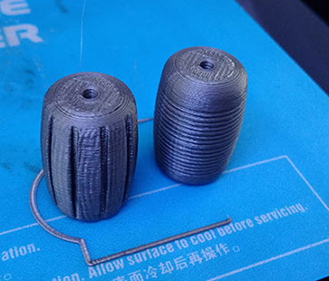
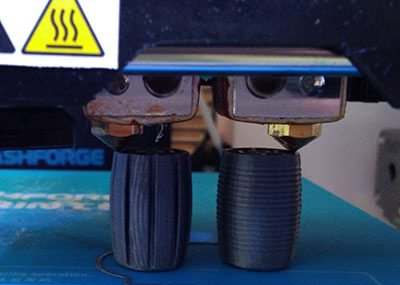
Improvement in Roller of wheels
During my Presentation with nils, i get suggestion from nils to design topography over roller which will help to increase the friction with surface considering changes suggested i Design 2 rollers design on which i have given two different type of topography ,i design them in fusion 360 and print them using flash-forge dreamer but when i tested them find that they are not good as it create lot more jerk in movement of wheel and this topography will get eroded on moving wheel as rubbing of such surface on floor will damage the pattern made on roller periphery
Coating rubber on Rollers
i also tried coating the wheels roller using rubber as liquid rubber as it is available in nearby area , where they use it for making mold of goddess statue ,i used the same for coating on roller as this thing will help in improving the traction with surface and move more smooth movement of roller but this practice is unsuccessful as rubber is not sicken properly on PLA also uneven coating result in jerk in movement of roller so i did't use it
Process of coating
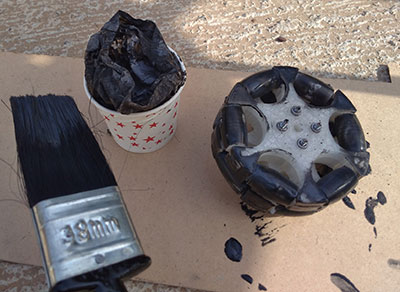
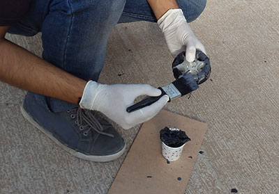
For coating rubber you need to coat layer by layer as coat one layer than let it dry than coat another layer than wait for 2-3 minute and let it dry in this way you can coat rubber layers on roller as ,i am coating in whole wheel as extra rubber layer you can easily remove by simply cutting it out and pull it , as i was doing this for testing may be this is not best practice to do this work
Conclusion
it was really challenging when you have to integrate everything you learned and put them in making one single product but doing this exercise will help you to understand key concept of prototyping and making any product , also you have to do everything in particular set time so you need to decide what is important and how much time i can give to one thing and sometime while making your final project you need to do things parallel but its fun doing this ,i am happy as my project is working fine.

This work by Gaurav wadhwa is licensed under a Creative Commons Attribution-NonCommercial 4.0 International License.