Welcome to the page containing the behind the scenes for my fab academy final project! ENJOY!
At the start of fab Academy, I was in my final year at Unviersity, with my final year project due date around the same time as my fab lab final project. Because of this, I intially aimed to tie the two projects together. My University final year project was to be a game that I was planning making myself, and I wanted to pair it by creating a controller for the game in fab academy. However after slightly altering my University final project, my fab academy final project changed too. Now it is based on my passion for dance. I came about my wearable LED shirt after performing some dance routines I had come up with during my transit to and from the lab to Luiz, and he suggested doing something related to dance...one thing led (no pun intended) to another and voila! The Dance of the LEDs was created.
As of recently, I am having to change my final project idea as my university final project is no longer a game but will be a radio piece in the form of an audiobook. I guess you could potentially call it an audiogame?
So far one of my ideas is to create a lamp that when lit portrays star-like constellations on surfaces. But as this is still too easy, I need to either figure out how to develop the idea OR think of something else...
06.06.2018 - Sat down with Luiz and wrote out all the things that my project includes (weeks wise) and which weeks that I'm missing I can incorporate. I had done some research, or attempted to do some on the gyroscope board now that it is here, but unfortunetly, everyone seems to either be using an arduino, a flora board, or their writing is basically latin in my eyes. So I've shared my findings, the ones that look like they might yield some helpful advice or hints in directions to take with Luiz in the hopes that he can make sense out of them.
This project involves the following weeks:
There was these cool kinetic motion reactive led gloves that, well, looked pretty cool: https://futuristiclights.com/products/kinetic-motion-reactive-led-glove-set They sort of remind me of Kelly's gloves even though they have different functions...
Being a music student, of course this appealed to me a lot; an LED music visualizer:
Poppy share this with me - it's based off/inspired by the Old Spice commerical that features Terry Crews creating music by flexing his muscles: https://blog.arduino.cc/2018/06/04/making-music-with-your-muscles/
And being a dancer, I thought this was cool too. Thought only for a while, because then it got boring and repetitive.
For this project I will require:
For this board I will require:
Most in the list are double to account for the second board.
I got myself a white shirt. Whilst I was in the store I tested to see whether my phone's torch could shine through and if so, by how much. Lukcily it was fine so I could only assume (and when I later tested I was correct) that the LEDs would shine through just fine. Initially by that stage I wasn't sure about the placement of the LEDs. All I knew is that I wanted them to "wrap" around my arms. I felt that if they were just a long strip down my arm, if I moved my arm in certain places, the LEDs would be out of sight. This way there would be some LEDs always in sight.
I then brainstormed about how to incoporate them best. One thing I needed to keep in mind was cleanliness and what would look best visually (what would be aesthetically pleasing). I came up with 3 ideas:
I went for the last one in the end because I felt it was the most clean and cool looking one.
Unforunetly, it's been a while since I used LEDs, as my last few projects have been with RGB ones, and before that, simply soldering them on. My breadboard days of the simple LED life were temporarily forgotten. Luckily this guy was a huge helping in revamping my memory:
I downloaded the gyroscope's library from website: LSM6 Arduino Library and installed lms6 pololu library in arduino
        /*
The sensor outputs provided by the library are the raw
16-bit values obtained by concatenating the 8-bit high and
low accelerometer and gyro data registers. They can be
converted to units of g and dps (degrees per second) using
the conversion factors specified in the datasheet for your
particular device and full scale setting (gain).

Example: An LSM6DS33 gives an accelerometer Z axis reading
of 16276 with its default full scale setting of +/- 2 g. The
LA_So specification in the LSM6DS33 datasheet (page 11)
states a conversion factor of 0.061 mg/LSB (least
significant bit) at this FS setting, so the raw reading of
16276 corresponds to 16276 * 0.061 = 992.8 mg = 0.9928 g.
*/

#include <Wire.h>
#include <LSM6.h>

LSM6 imu;

char report[80];

void setup()
{
  Serial.begin(9600);
  Wire.begin();

  if (!imu.init())
  {
    Serial.println("Failed to detect and initialize IMU!");
    while (1);
  }
  imu.enableDefault();
}

void loop()
{
  imu.read();

  snprintf(report, sizeof(report), "A: %6d %6d %6d    G: %6d %6d %6d",
    imu.a.x, imu.a.y, imu.a.z,
    imu.g.x, imu.g.y, imu.g.z);
  Serial.println(report);

  delay(100);
}
I attempted to use this "instructables link" to hack and use my own gyroscope, but unfrotunetly I was not able to because the file was referencing other files, meaning that I could not simply hack and replace the gyroscope in use. At least not to my knowledge.
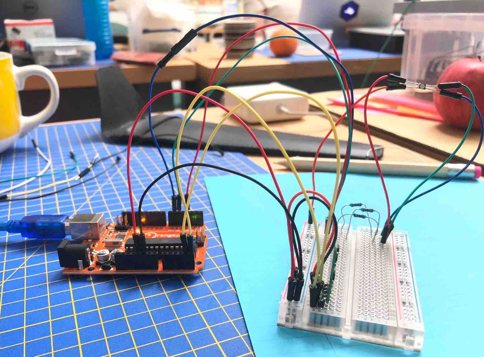
I moved on to my first proper test. As my RGB LED strip was yet to arrive, I used a small SMD RGB LED and soldering jump wires to it, and using the Orange pip Kona328 (as a substitute for the arduino). It worked but the red LED was considerably weaker than the other two colors. To ensure this was an issue with the LED and not the soldering or perhaps having fryed, another one was soldered. But the same thing happened.
I then attempted to hook up two RGB LEDs to the bueno board I made a while back. At first it did not work. The only thing that worked was the LED on the bueno board. I still do not know why though. I couldn't get assistance, I was told to trouble shoot, even though I had spent 30 minutes troubleshooting. I was told to make a diagram of how it would be connected. Although I didn't see the purpose in doing so and still do not, I made one anyways. I suppose it's good to have a reference point? I decided to break things down. I reconnected the bread board to the arduino and the light powered on, which worked. So I'm not sure where I went wrong. Initially the second RGB LED refused to go on, which led me to believe it was no longer working. Especially since I tried to directly connect it. I then attempted to switch out the red jumper wire on the first RGB LED for the second one's, which for some reason worked. But when I tried to connect it on its own again it went back to not working. I decided to just try and ignore this because I knew I was not going to get any help and just be told that it's "simple". I almost gave up but deicded to give things one last shot. I rehooked everything (not including the second RBG LED) back the bueno board, and it worked. I'm not sure why, but at least it works. I did however notice that some of the pin out headers were not alligned nicely enough to make it obvious which was which when referring to Luiz's diagram, this is something I intend to make better on my own latter version, however this was not the inital problem. I know this because this time only one color worked. But when I got the outputs correct on arduino it was better.
I think tried to hook up the second one carefully using my diagram whenever I got confused. I made sure to simply copy the first boards layout. For ground for the second board, I used the other ground form the oin header 3x2. Everything else I used jumper wires to connect the boards. For example since the bueno board only has one place to input for VCC, SCL and SDA, I used jumper wires to share the connection from one board to the other.
When I ran this through arduino, all LEDs powered on. Unfortunetly, I think that because power is being shared, it is messing up the first RGB LED as it keeps "jumping" /"flickering" between colors once in a while (see video). And the second RGB LED does not change color when I move the breadboard around. I intially thought I setup the read on ardunio incorrectly, but as you can see in the video, it recognizes that the gyroscope is rotating. So I am not sure why it does not change color. This is something I will have to look into. Although I must also recognise that now that my RGB LED strips are ready to be collected, this might not be an issue I need to face.
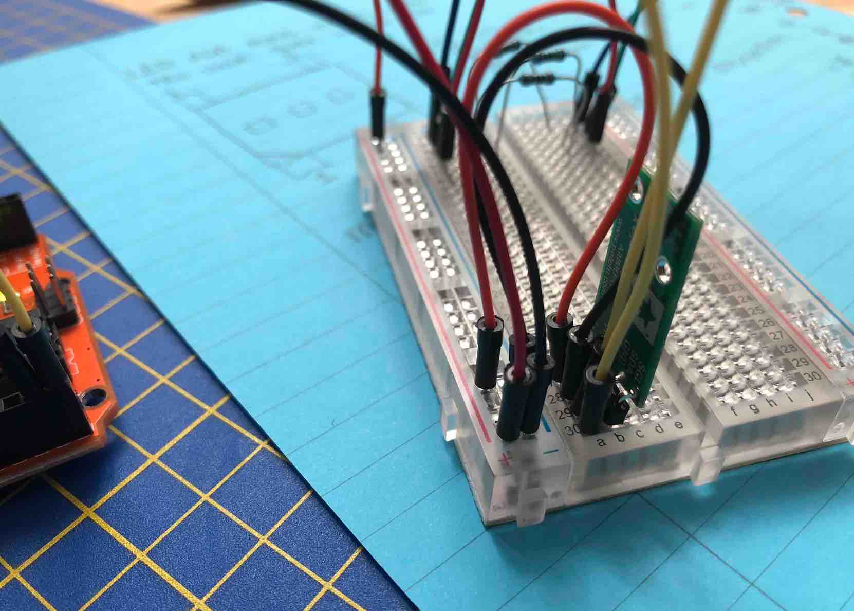
After reciving my LED strip, I got to testing it.
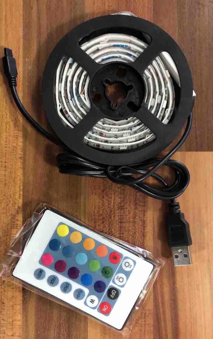
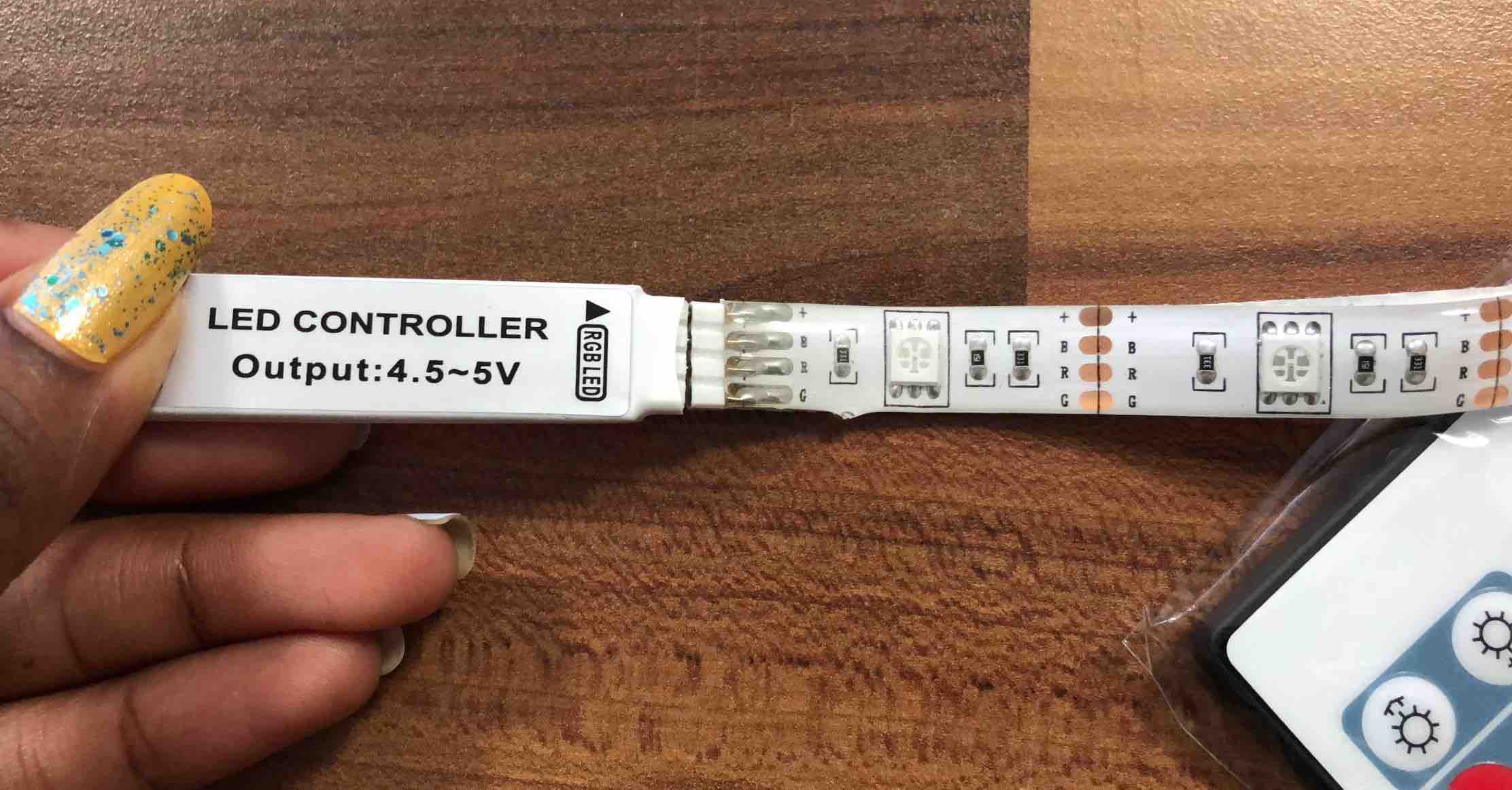
To my luck it works fine. I did not need to reconstruct anything other than simply soldering some jump wires to the LED strip I had cut. I decided to cut two off, because I wanted to see if it would work with multiple, but also to sort of get an idea. I would have done more but if this plan were to fail, I would have stood the chance of wasting 1 meter of LEDs. Not the plan.
Actually having the LED strip has helped me better visualize what the final product could be like. This is just me again reaffirming the fact that I work with tangile things not theories. Things do not always make sense to me until it's actually infront of me happening. I am currently looking towards instead of having a straight line, have the LEDs "curl" or "wrap" around my arms to my shoulder. I think this is better because then when I move my arms, no matter the direction (other than behind my back), the Leds will always be visible. Also, whilst writing this, I have realised that instad of having the gyroscope on my shoulders or back with the bueno board, it should strategically speaking, be placed on my forearm area. This is because this is where the most movement can be registered. On my shoulder, only movements detected will be my shoulder. Same applies to if it were on my back. On my bicep, it will record shoulder movement and bicep, but if I were to move my forearm, little to no detection will be made. However, having it on my forearm, I predict will record my whole arms movement.
Once it was working, I set to something I've been wanting to do/control: the colors. I think it would be cool to be able to control what colors are being outputed.so I looked into these sites codes...:
I attempted hack them by intergrating them both into my LSM6 code:
           /*

The sensor outputs provided by the library are the raw

16-bit values obtained by concatenating the 8-bit high and

low accelerometer and gyro data registers. They can be

converted to units of g and dps (degrees per second) using

the conversion factors specified in the datasheet for your

particular device and full scale setting (gain).


Example: An LSM6DS33 gives an accelerometer Z axis reading

of 16276 with its default full scale setting of +/- 2 g. The

LA_So specification in the LSM6DS33 datasheet (page 11)

states a conversion factor of 0.061 mg/LSB (least

significant bit) at this FS setting, so the raw reading of

16276 corresponds to 16276 * 0.061 = 992.8 mg = 0.9928 g.

*/


#include <Wire.h>

#include <LSM6.h>


int ledR = 6;           // the PWM pin the LED is attached to

int ledG = 9;           // the PWM pin the LED is attached to

int ledB = 10;           // the PWM pin the LED is attached to


int ledR_a = 5;
int ledB_a = 13;


//int brightness = 0;    // how bright the LED is

//int fadeAmount = 5;    // how many points to fade the LED by


LSM6 imu;


char report[80];


void setup()

{


  pinMode(ledR, OUTPUT);

  pinMode(ledG, OUTPUT);

  pinMode(ledB, OUTPUT);


  pinMode(ledR_a, OUTPUT);
    pinMode(ledB_a, OUTPUT);


  Serial.begin(9600);

  Wire.begin();


  if (!imu.init())

  {

    Serial.println("Failed to detect and initialize IMU!");

    while (1);

  }

  imu.enableDefault();

}


void loop()

{

  /*
  setColor(255, 0, 0);  // red
  delay(1000);
  setColor(0, 255, 0);  // green
  delay(1000);
  setColor(0, 0, 255);  // blue
  delay(1000);
  setColor(255, 255, 0);  // yellow
  delay(1000);
  setColor(80, 0, 80);  // purple
  delay(1000);
  setColor(0, 255, 255);  // aqua

 */

  imu.read();


/*snprintf(report, sizeof(report), "A: %6d %6d %6d    G: %6d %6d %6d",

    imu.a.x, imu.a.y, imu.a.z,

    imu.g.x, imu.g.y, imu.g.z);

   Serial.println(report);

*/


int gyroX = imu.a.x;

int gyroY = imu.a.y;

int gyroZ = imu.a.z;


int gyroX_a = imu.a.x;
int gyroY_a = imu.a.y;
int gyroZ_a = imu.a.z;


gyroX = map(gyroX, -20000, 20000, 0, 255);

gyroY = map(gyroY, -20000, 20000, 0, 255);

gyroZ = map(gyroZ, -20000, 20000, 0, 255);


gyroX_a = map(gyroX_a, -20000, 20000, 0, 255);

gyroY_a = map(gyroY_a, -20000, 20000, 0, 255);

gyroZ_a = map(gyroZ_a, -20000, 20000, 0, 255);


// Serial.println((imu.a.x), (imu.a.y), (imu.a.z));

Serial.print("GyroX:");
Serial.println(gyroX);

Serial.print("GyroY:");
Serial.println(gyroY);

Serial.print("GyroZ:");
Serial.println(gyroZ);


Serial.print("GyroX_a:");
Serial.println(gyroX_a);

Serial.print("GyroY_a:");
Serial.println(gyroY_a);

Serial.print("GyroZ_a:");
Serial.println(gyroZ_a);


  // set the brightness of pin 3, 5, 6:

  analogWrite(ledR, gyroX);

   analogWrite(ledG, gyroY);

    analogWrite(ledB, gyroZ);


      analogWrite(ledR_a, gyroX_a);

   analogWrite(ledB_a, gyroY_a);

    analogWrite(ledR_a, gyroZ_a);


 // change the brightness for next time through the loop:

//  brightness = brightness + fadeAmount;


  // reverse the direction of the fading at the ends of the fade:

//  if (brightness <= 0 || brightness >= 255) {

//    fadeAmount = -fadeAmount; }

  // wait for 30 milliseconds to see the dimming effect

//  delay(30);


  delay(100);

}


/*
 void setColor(int red, int green, int blue)
{
  #ifdef COMMON_RBGLed
    red = 100 - red;
    green = 155 - green;
    blue = 255 - blue;
  #endif
  analogWrite(ledR, red);
  analogWrite(ledG, green);
  analogWrite(ledB, blue);
}

*/

void mapColor(int red, int green, int blue)

{

// #ifdef COMMON_RBGLed
    red = 100 - red;
    green = 0 - green;
    blue = 0 - blue;

//    yellow =
  int gyroX = imu.a.x;


  if (gyroX = 225)
  {

    analogWrite(ledR, red);
     analogWrite(ledG, green);
     analogWrite(ledG, blue);

  }
  //else
   // analogWrite(ledR, red);
   //  analogWrite(ledG, green);
   //  analogWrite(ledG, blue);
}

Sophie Kiarie, Fab Academy 2018
Unfortunetly, this got me nowhere. So I tried to edit this a bit...
Here the results of this code:
        /*

The sensor outputs provided by the library are the raw

16-bit values obtained by concatenating the 8-bit high and

low accelerometer and gyro data registers. They can be

converted to units of g and dps (degrees per second) using

the conversion factors specified in the datasheet for your

particular device and full scale setting (gain).


Example: An LSM6DS33 gives an accelerometer Z axis reading

of 16276 with its default full scale setting of +/- 2 g. The

LA_So specification in the LSM6DS33 datasheet (page 11)

states a conversion factor of 0.061 mg/LSB (least

significant bit) at this FS setting, so the raw reading of

16276 corresponds to 16276 * 0.061 = 992.8 mg = 0.9928 g.

*/


#include <Wire.h>

#include <LSM6.h>


int ledR = 6;           // the PWM pin the LED is attached to

int ledG = 9;           // the PWM pin the LED is attached to

int ledB = 10;           // the PWM pin the LED is attached to


int rVal = 0;   // Variables to store the values to send to the pins
int gVal = 0;
int bVal = 0;

int gyroValX = 0;
int gyroValY = 0;
int gyroValZ = 0;


//int brightness = 0;    // how bright the LED is

//int fadeAmount = 5;    // how many points to fade the LED by


LSM6 imu;


char report[80];


void setup()

{
  pinMode(ledR, OUTPUT);

  pinMode(ledG, OUTPUT);

  pinMode(ledB, OUTPUT);


 // pinMode(ledR_a, OUTPUT);
 // pinMode(ledB_a, OUTPUT);


  Serial.begin(9600);

  Wire.begin();


  if (!imu.init())

  {

    Serial.println("Failed to detect and initialize IMU!");

    while (1);

  }

  imu.enableDefault();

}


void loop()

{

  imu.read();


/*snprintf(report, sizeof(report), "A: %6d %6d %6d    G: %6d %6d %6d",

    imu.a.x, imu.a.y, imu.a.z,

    imu.g.x, imu.g.y, imu.g.z);

   Serial.println(report);

*/


int gyroX = imu.a.x;
int gyroY = imu.a.y;
int gyroZ = imu.a.z;


int gyroX_a = imu.a.x;
int gyroY_a = imu.a.y;
int gyroZ_a = imu.a.z;


gyroX = map(gyroX, -20000, 20000, 0, 510);
gyroY = map(gyroY, -20000, 20000, 0, 510);
gyroZ = map(gyroZ, -20000, 20000, 0, 510);


//gyroX_a = map(gyroX_a, -20000, 20000, 0, 255);
//gyroY_a = map(gyroY_a, -20000, 20000, 0, 255);
//gyroZ_a = map(gyroZ_a, -20000, 20000, 0, 255);


// Serial.println((imu.a.x), (imu.a.y), (imu.a.z));

Serial.print("GyroX:");
Serial.println(gyroX);

Serial.print("GyroY:");
Serial.println(gyroY);

Serial.print("GyroZ:");
Serial.println(gyroZ);


/*

Serial.print("GyroX_a:");
Serial.println(gyroX_a);

Serial.print("GyroY_a:");
Serial.println(gyroY_a);

Serial.print("GyroZ_a:");
Serial.println(gyroZ_a);
*/


  // set the brightness of pin 3, 5, 6:

  analogWrite(ledR, gyroX);
  analogWrite(ledG, gyroY);
  analogWrite(ledB, gyroZ);


 // analogWrite(ledR_a, gyroX_a);
 // analogWrite(ledB_a, gyroY_a);
 // analogWrite(ledR_a, gyroZ_a);


 // change the brightness for next time through the loop:
 // brightness = brightness + fadeAmount;


 // reverse the direction of the fading at the ends of the fade:
 // if (brightness <= 0 || brightness >= 255) {

 // fadeAmount = -fadeAmount; }

 // wait for 30 milliseconds to see the dimming effect

 //  delay(30);


gyroValX = analogRead(gyroX);   // read the potentiometer value at the input pin

  if (gyroValX < map(gyroX, 0, 310, 200, 300))  // Lowest third of the potentiometer's range (0-340)
  {
    //gyroVal = (gyroVal * 3) / 4; // Normalize to 0-255

    rVal = 0;  // Red from full to off
    gVal = 0;        // Green from off to full
    bVal = 0;             // Blue off
    delay (50);
  }

  else  if (gyroValX > 200)// Upper third of potentiometer"s range (682-1023)
  {
    //gyroVal = ( gyroVal-20) / 4; // Normalize to 0-255

    rVal = 0;    // Red from off to full
    gVal = 0;    // Green off
    bVal = 255;  // Blue from full to off
delay (50);
  }
}


/*gyroValY = analogRead(gyroY);   // read the potentiometer value at the input pin

  if (gyroValY < map(gyroX, 0, 310, 100, 200)))  // Lowest third of the potentiometer's range (0-340)
  {
    //gyroVal = (gyroVal * 3) / 4; // Normalize to 0-255

    rVal = 0;  // Red from full to off
    gVal = 0;  // Green from off to full
    bVal = 0;  // Blue off
  }

  else  if (gyroValY > map(gyroX, 0, 310, 100, 200)))// Upper third of potentiometer"s range (682-1023)
  {
    //gyroVal = ( gyroVal-20) / 4; // Normalize to 0-255

    rVal = 0;   // Red from off to full
    gVal = 0;   // Green off
    bVal = 255; // Blue from full to off

  }

  gyroValZ = analogRead(gyroZ);   // read the potentiometer value at the input pin

  if (gyroValZ <= 100)  // Lowest third of the potentiometer's range (0-340)
  {
    //gyroVal = (gyroVal * 3) / 4; // Normalize to 0-255

    rVal = 0;  // Red from full to off
    gVal = 0;  // Green from off to full
    bVal = 0;  // Blue off
  }

  else  if (gyroValZ >= 100 )// Upper third of potentiometer"s range (682-1023)
  {
    //gyroVal = ( gyroVal-20) / 4; // Normalize to 0-255

    rVal = 0;   // Red from off to full
    gVal = 0;   // Green off
    bVal = 255; // Blue from full to off

  }


  analogWrite(ledR, rVal);   // Write values to LED pins
  analogWrite(ledG, gVal);
  analogWrite(ledB, bVal);
}


//  delay(100);

//}


/*
 void setColor(int red, int green, int blue)
{
  #ifdef COMMON_RBGLed
    red = 100 - red;
    green = 155 - green;
    blue = 255 - blue;
  #endif
  analogWrite(ledR, red);
  analogWrite(ledG, green);
  analogWrite(ledB, blue);
}


void mapColor(int red, int green, int blue)

{

// #ifdef COMMON_RBGLed
    red = 100 - red;
    green = 0 - green;
    blue = 0 - blue;

//    yellow =
  int gyroX = imu.a.x;


  if (gyroX = 225)
  {

    analogWrite(ledR, red);
     analogWrite(ledG, green);
     analogWrite(ledG, blue);


  }
  //else
   // analogWrite(ledR, red);
   //  analogWrite(ledG, green);
   //  analogWrite(ledG, blue);
}
*/

Sophie Kiarie, Fab Academy 2018
As you can see in the video below, the colors aligned, but it was not always consistent and it would suddenly change color instead ofgradually changing color. Having that would eventually end up "hurting" the eyes of viewers.
I tried to read into this page: "https://playground.arduino.cc/Code/BiColorLED" to find out more about controlling them but I only saw things that I had seen in other codes (terms), and I felt like I was going nowehere.
After a few more failed attempts, with the help of Kyle, I started upon a newer method - setting up intergers that contained the colors I wanted to use which could be called upon when certain "angles" are reached. I already know that
But i wasn't sure about the other colors. So I used this site which has a color wheel to help me figure out the RGB for the colors:
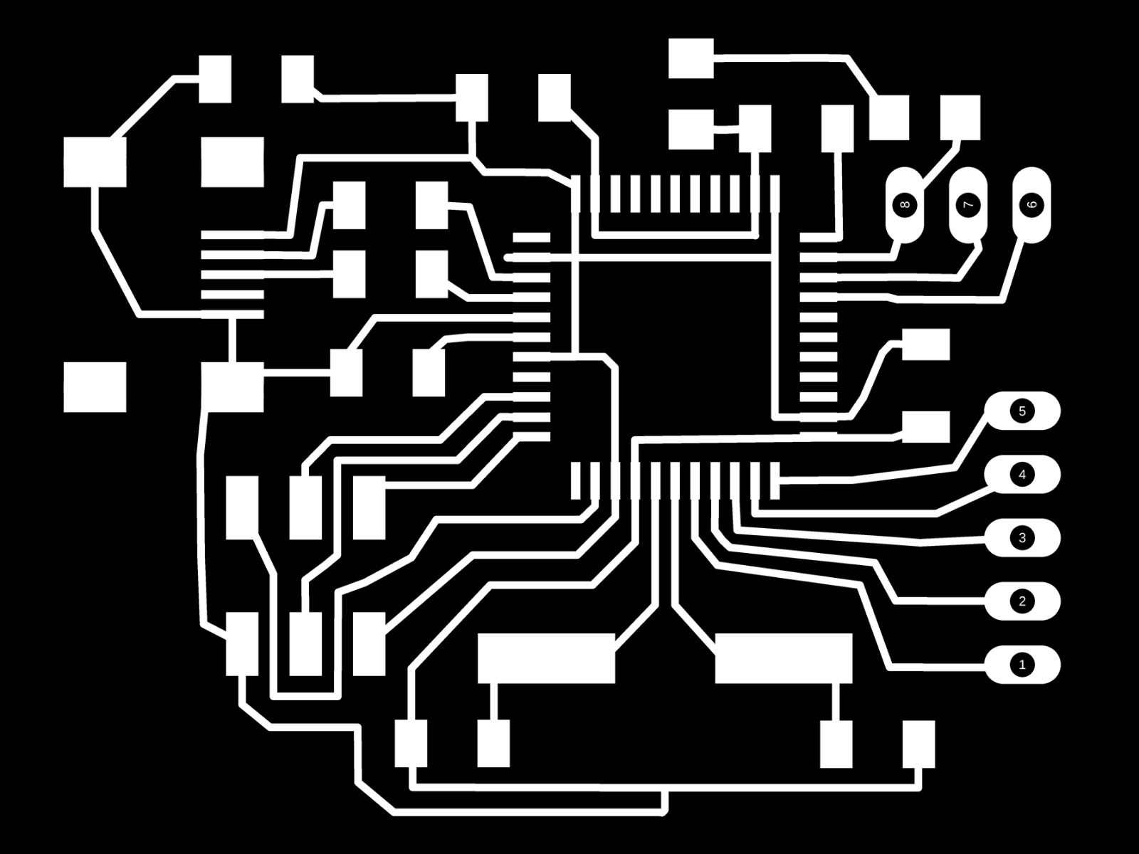
I noted from previously doing Luiz board that the traces surrounding the Atmega were really small and therefore a real pain to solder. So for mine I made sure to make the traces slightly longer so that I wouldn't have to spend ages trying to make sure solder wasn't flowing on to other traces or simply even just getting the sodler onto the pag and the chip leg.
I intially created 3 different boards. I started off by using my echo world board as my starting point and developed it from there, including the thigns I would need (like the 7 pin headers) and removing things I wouldn't need (such as the switch button). I kept the LED on because it would serve well when I'm troubleshooting my board so I can see if the problems lie with the LEDs or something else.
However, after showing my board to Luiz, he pointed out that having an attiny 44 might not be a great idea as the LSM6 library might not support it. So I then went on to use the same Atmega 32u4 chip he had in his bueno bboard and somehat replaced all the traces with the new chip.
Luiz then pointed out that it might not work because of a VCC issue. Although I have some speculation that it might be because he recreated an arudino board and mine is a simple version of it, it might not be the case. He suggested using his Bueno Board and simplfying it. What I ended up doing was using his to simplfy, but also made the VCC connection he pointed out. Which is how I ended up with 3 different boards made in the span of a day, something I would not have been able to even closely achieve before. Having made a board practically from scratch including all the other versions I've made has helped me become more familiar with Eagle. That being said, Eagle can be EXTREMELY annoying and had it not been for it crashing my computer once in a while or it's near impossible screen navigation, I might have come further or finished this step faster.
My next issue was in illustator. I am still not great at it simply because the only times I use it are in the lab if it's related to me making a board that isn't "normal". Since the lab is my only way of using illustrator as I do not personally have it or Photoshop. That set me back a lot. Luckily I had the help of Kyle to figure things out I could not otherwise have, and I am now better at Illustator, but I still don't particularly care for it. I prefer Photoshop..but that's a story for another day.
I was surprised to see that my board was bigger than Luiz's, but I suppose perhaps it is because of the space I created in the end with the jumper resistors.
After that came the NEXT issue.... -.-
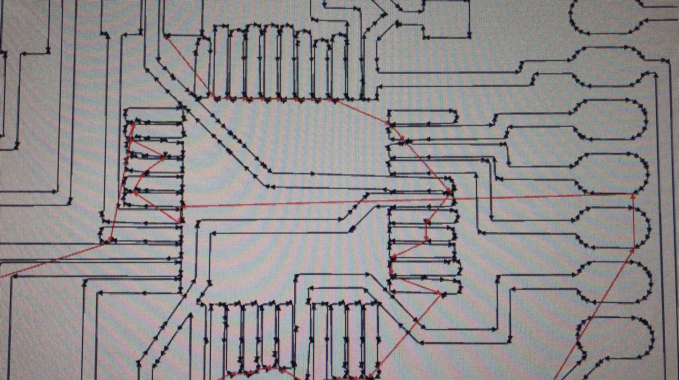
I had issus in fab mods. When I was trying to upload and calcualte my image, because of the miniscule size of the atemga 32u4's legs, it had a hard time calculating them in. It was almost as if the legs were too thick, but I know they were not (and I had my classmate Paul check), because on Eagle they are well spaced apart. I even went ahead on Illustrator and cleaned some legs out that I thought might be an issue. Luiz came to the rescue as he had experience. He suggested milling with a 0.4 drill bit and and offset of 4, then afterwards milling with a drill size 0.2 and an offset again of 4. This worked well to separate a majority of the legs but as you can see in the below image, not all of them were. I was initially going to reduce the Z value on the milling machine by 0.01, but Luiz suggested that that was not the best idea and stated I would be better off using a knife. I almost cut off an important trace!! That was close.
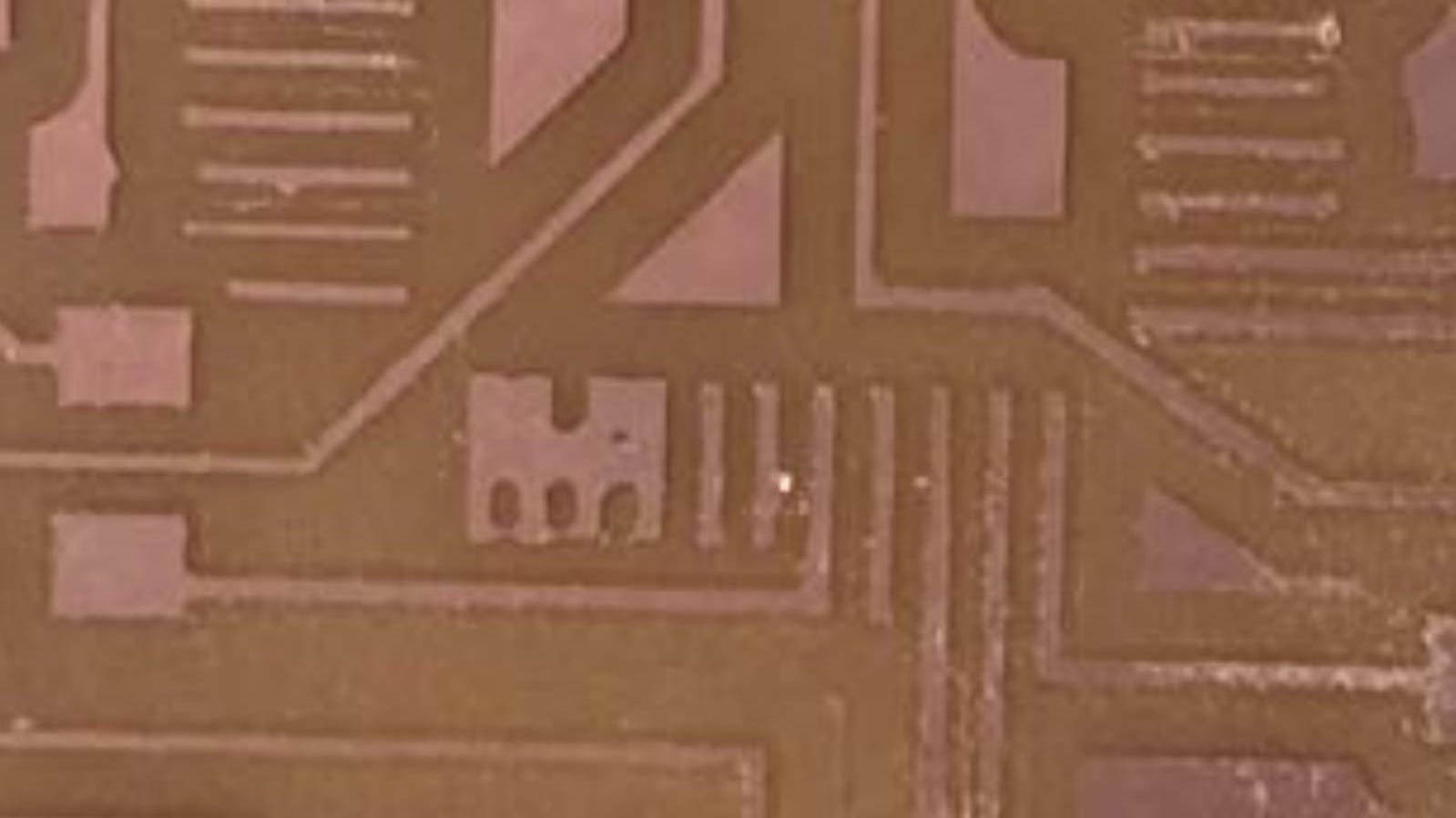
When I was milling the first time with the 0.4 drill bit, I noticed that at the top of my board, the copper had not been milled out well at all. It was way too much to use a knife, so I reduced the Z by 0.02. This was effective. I am not sure why that was even a needed step, but my guess is that the board was not placed on well or the wood needs to be surfaced again.
Once everything was milled I began to solder. Unfortunetly, not for long...
Whilst attempting to solder the traces to the Atemga's legs, I oversoldered accidentally resulting in two legs getting joined. I attempted to "desolder" it by "smoothing out" the solder evenly but this did not work. Next I tried using the solder gun. It worked to remove it atemga but then...one of the traces came off. As the traces and the legs are so thin and so therefore so fragile, I couldn't even fix this swith a wire.
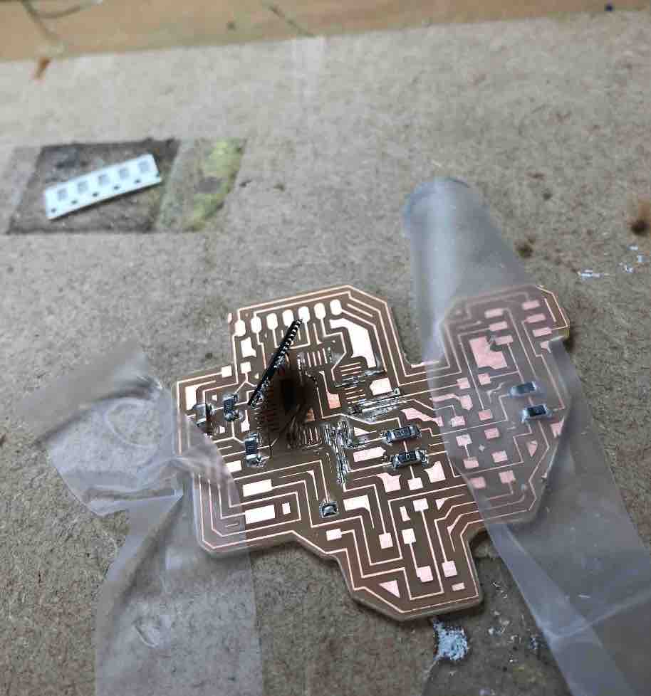
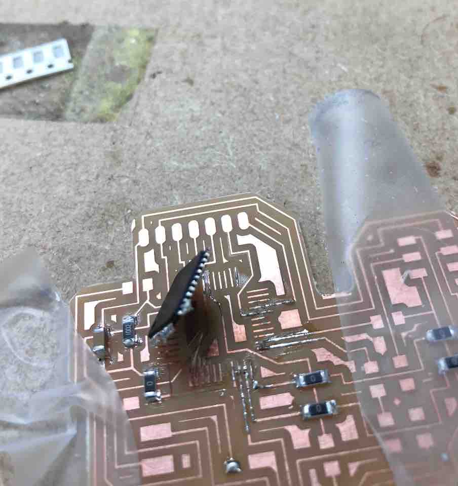
So I milled another board. This board came with it's own set of milling issues, first under-milling then over-milling to a point where traces had been removed. This of course meant another attempt was needed. It worked, and I had a few minor bumps along the way (such as part of the board chipping off (entirely) and me realizing that I had forgotten a trace in Eagle, but there were fixed with wires for the missing trace, and super glue combined with soldering for the chipped bit. Despite all of this though, it was when I got down to burning the board in Arduino, I realized that because I did not have a usb port on my board, it was basically useless. I had left it out to allow me leway to choose the method I was going to power my LEDs. So I had to give in and mill out my modified version of Luiz's "Bueno Board".
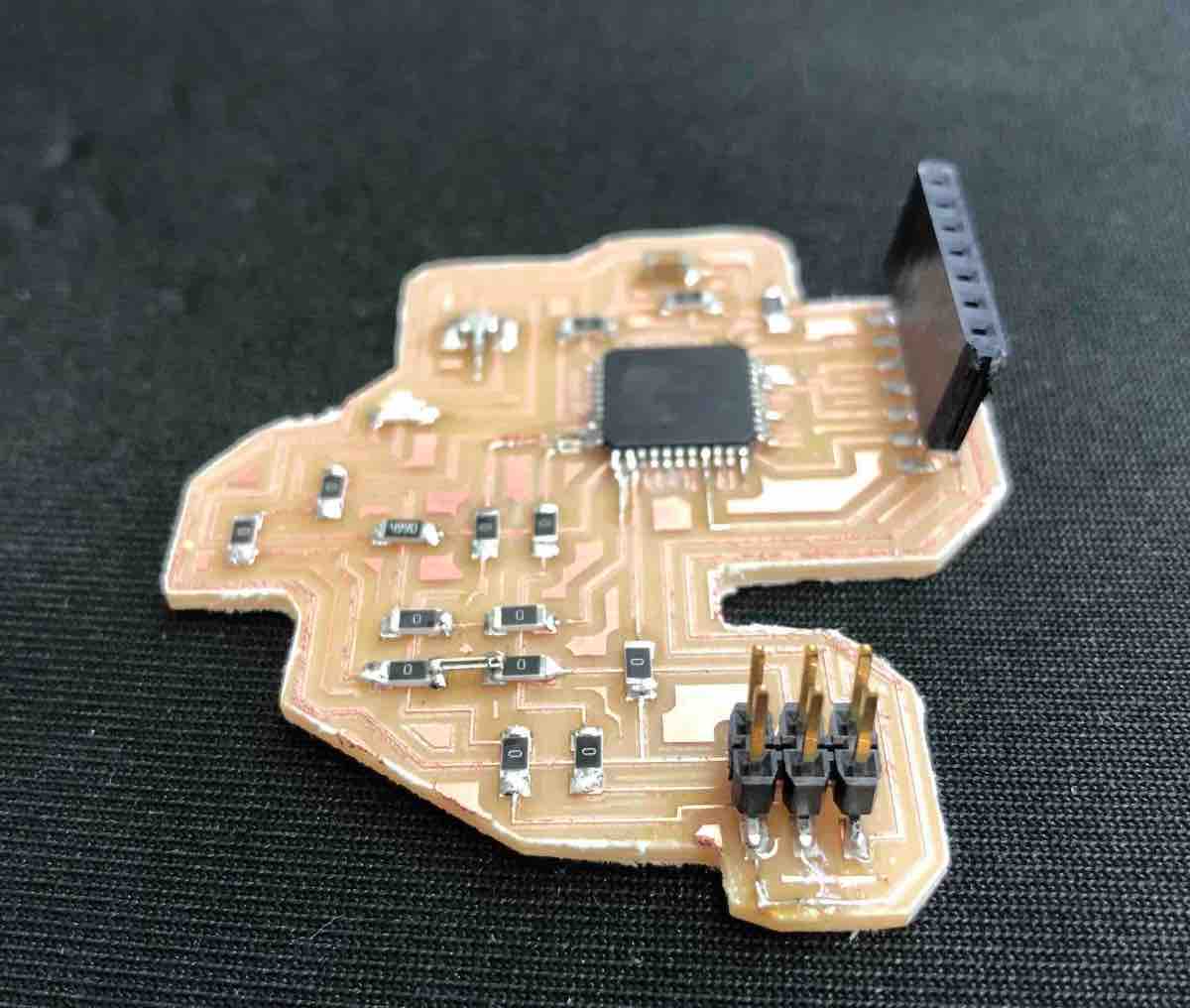
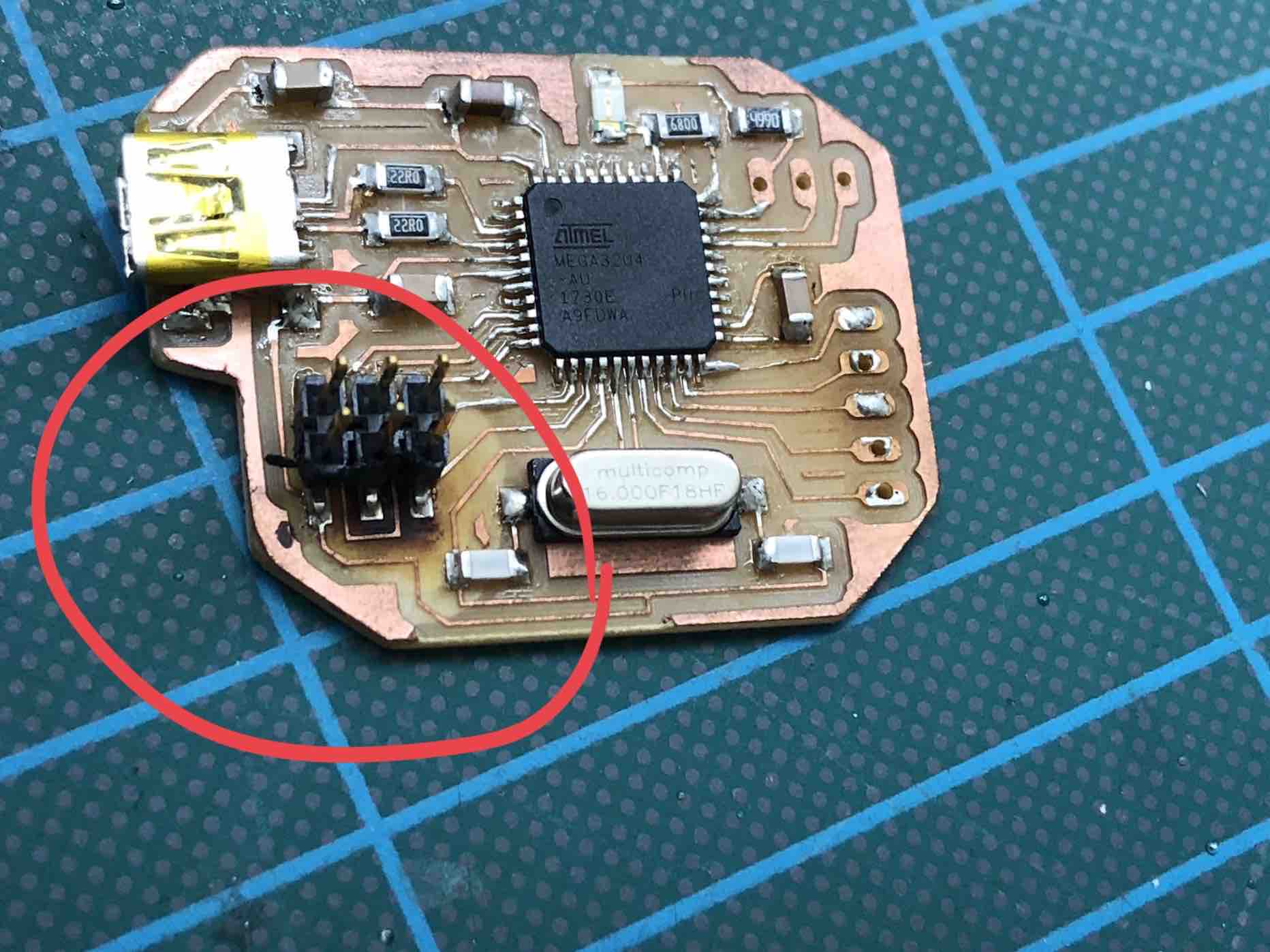
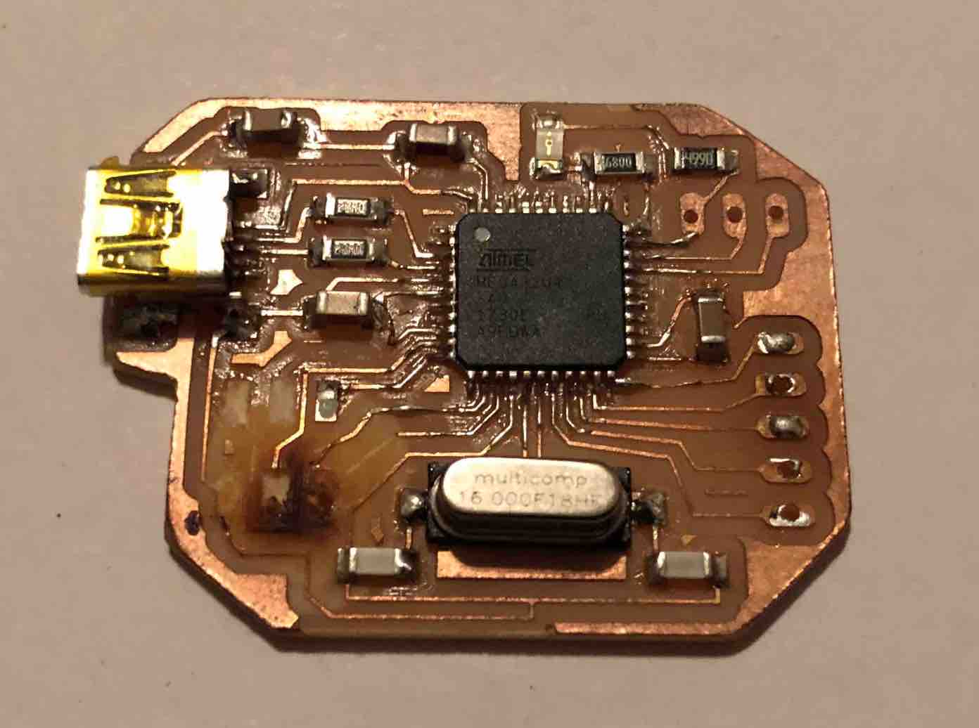
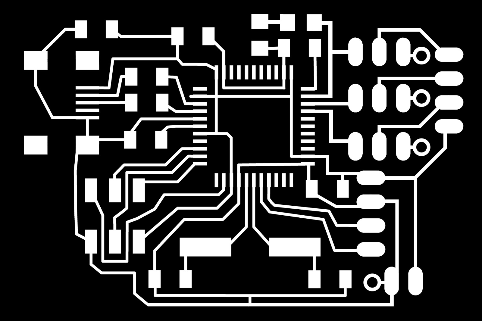
HOWEVER!....I foolishy did not consider the battery, rendering the board useless. In the end, I took Luiz's bueno board and altered it one last sucessful time. Meet the Mini Bueno Board version Sophie.
To make this board I needed to sit down and analyze the Bueno board and figure out firstly, what pins and connections I truly needed and which ones I could throw out (delete) from the eagle board. The next step was then to condesnse everything spacially as much and realistically as possible.

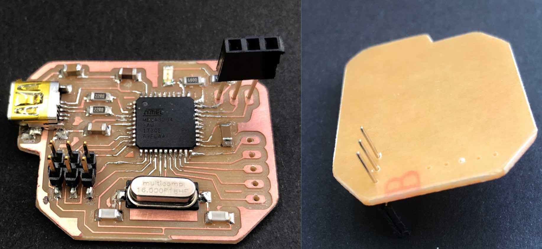
comparison image!!!!
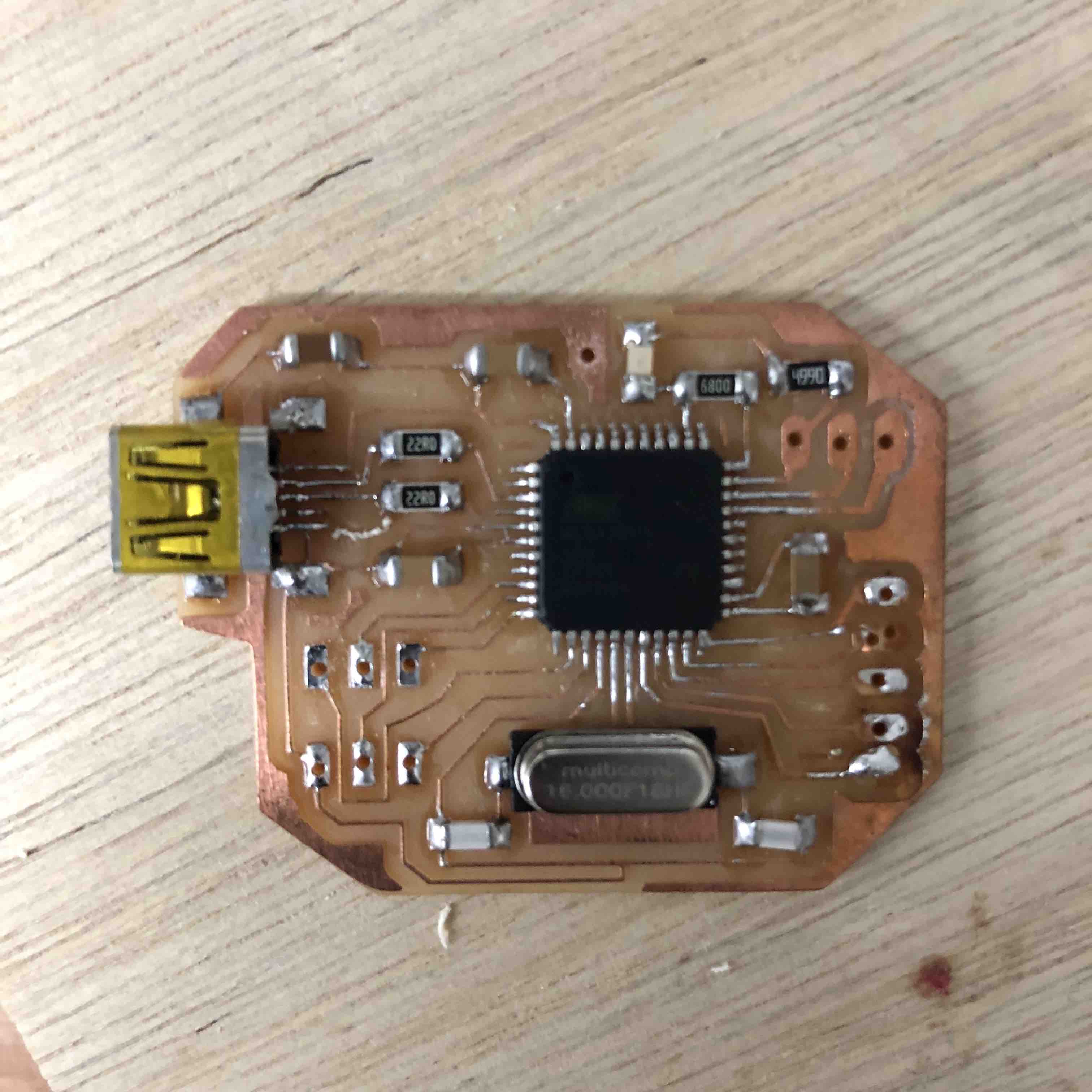
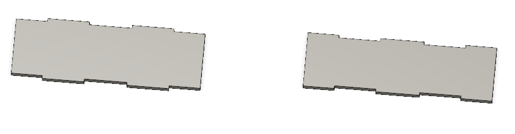
As you can see, the size difference is massive. It is so small it fits on my wrist either way with space left over, which is great because I don't want the board to show up much. It shouldn't copletley steal the attention.
It worked PERFECTLY. However, thanks to my global evaluator, I realized I was missing some vital points which are just future problems that could really harm my board.
This redesign required the following additions/alterations:
This was a suggestion made my Bas. However I did not understand why. So of course the way to find out why is to do research.
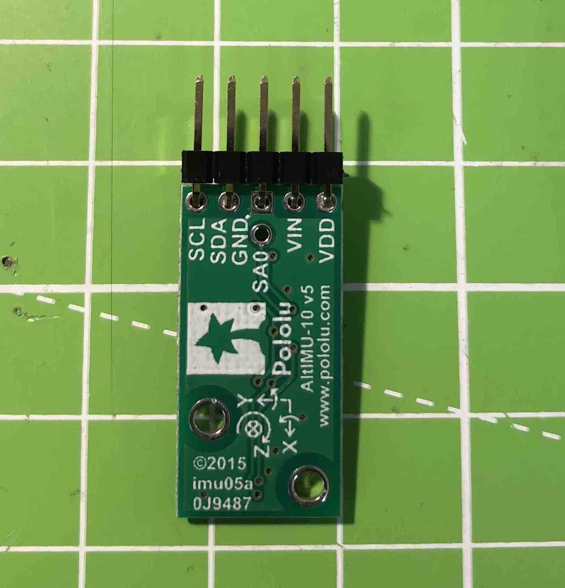
Upon doing my research I stumbled onto this site and after reading through it I hit the gold mine. There was the pinout diagram where it lists each pin out and describes it.
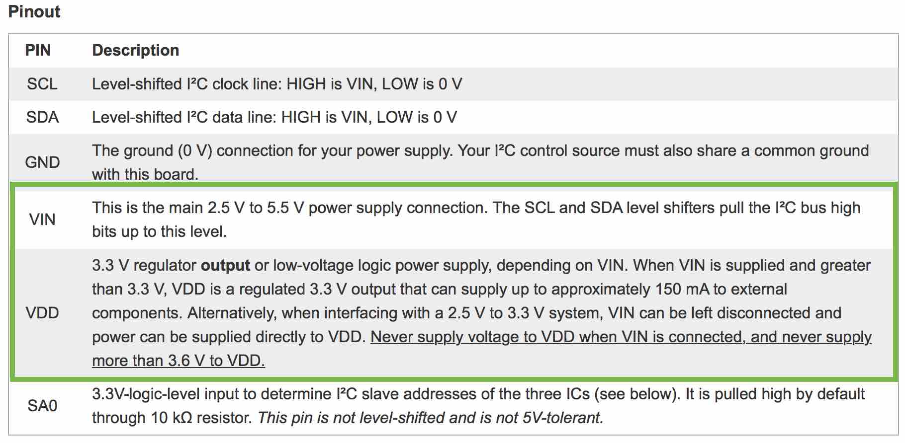
I noticed that because I am supplying more than 3.6V to my IMU, I cannt connect it directly to power, I have to connect it to VIN instead of VDD. This would have been ok though if it were 3V or less.
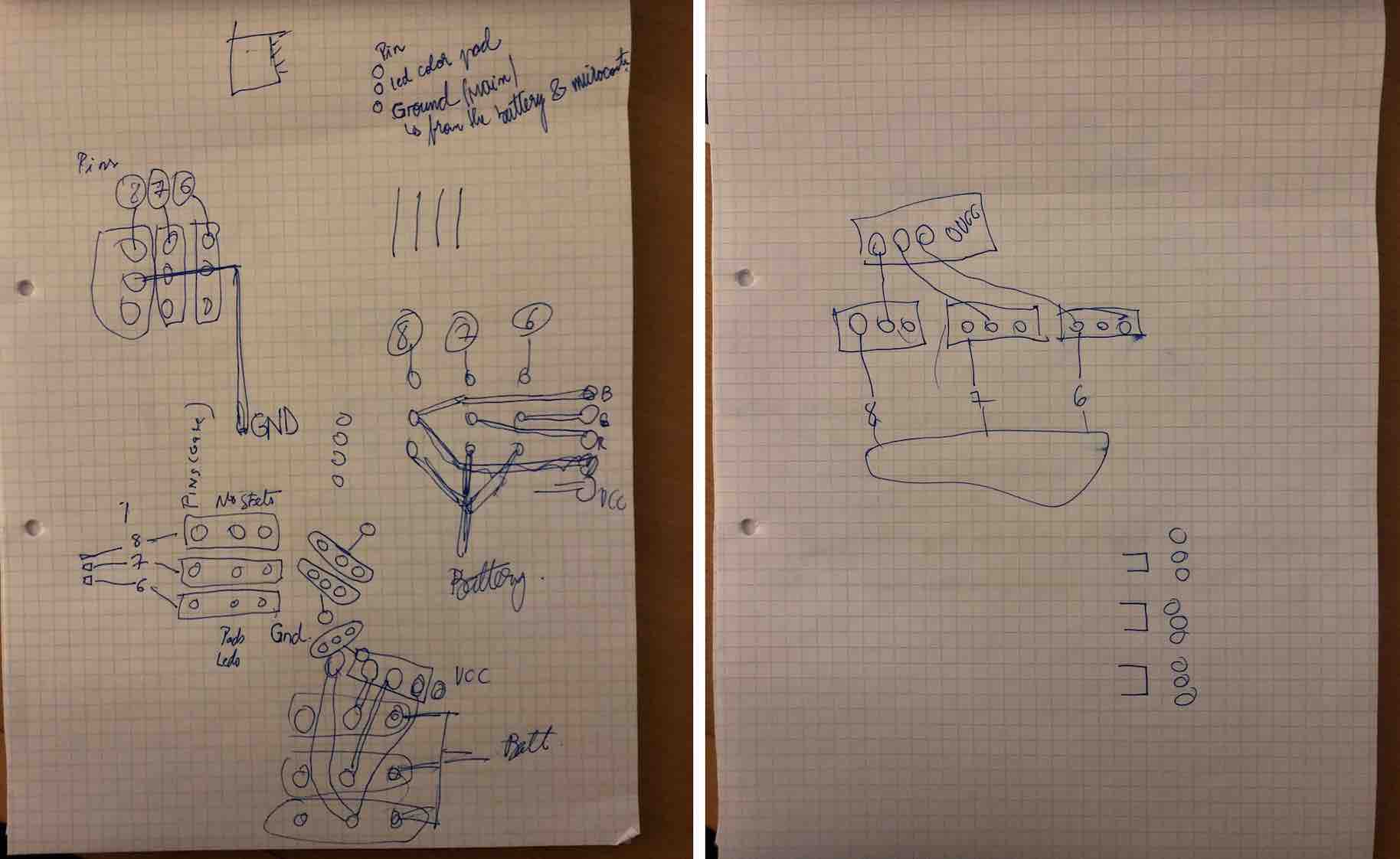
This redesign was tricky as the board was already perfectly small, so adding things would mean it getting bigger and that isn't what I want. So the aim was to keep things as logical as possible whilst still retaining as much of the previous size as possible. This was done by shifting pads and components placements around to make space for example the mosfets. The mosfets were the hardest part to redesign onto the board because of constantly being in that locked in moment where one method would would until the traces would be locked into one another.
This was designed in Photoshop as I already had the png of the previous board from eagle designed. Knowing the sizes from before of most of the components are researching helped. The aim would be then to do the same thing and drill holes through.Behold, the new design!
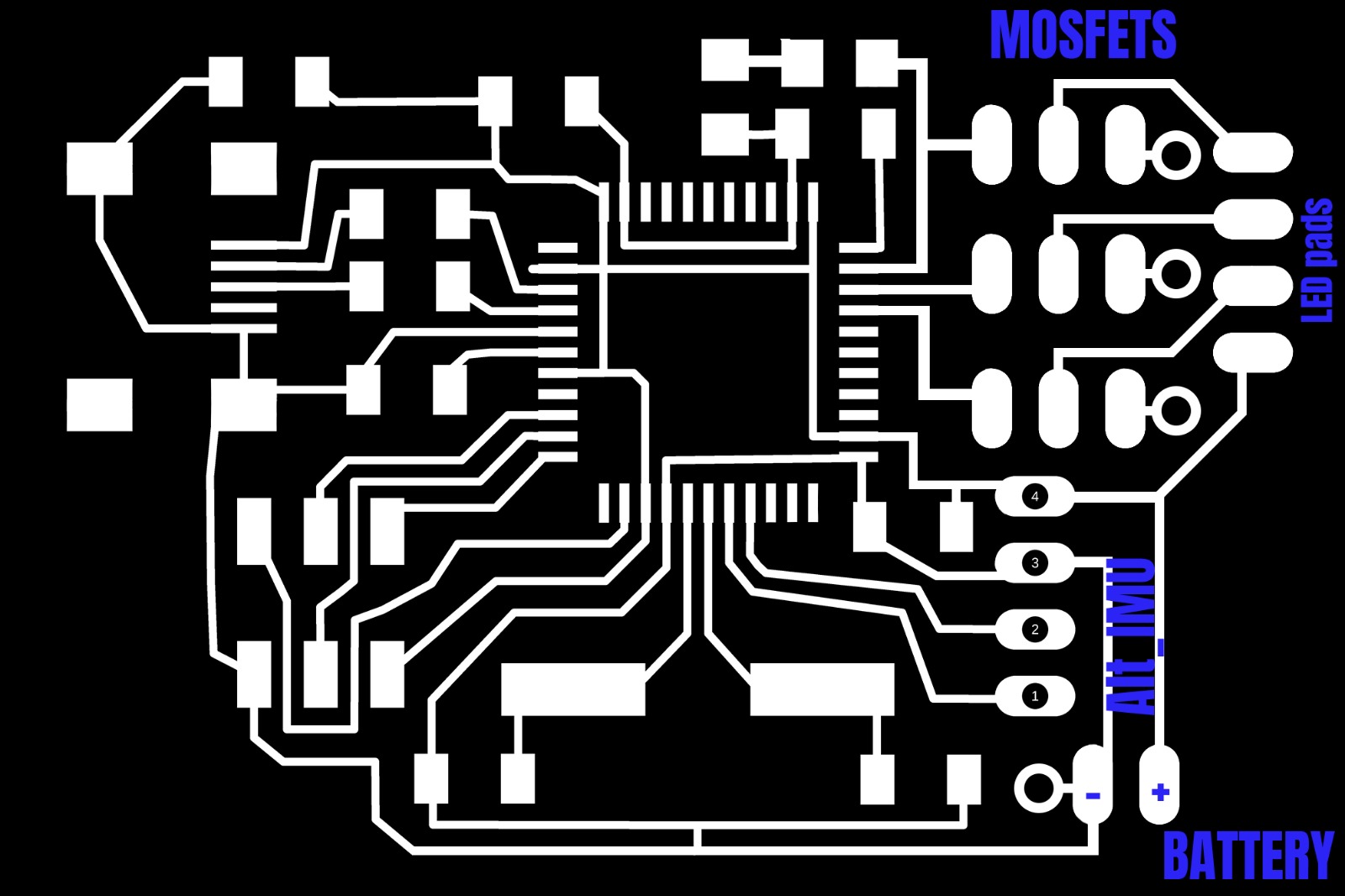
In the diagram above, the circle bits next to the battery and mosfet are places to drill to then ground them. This then requires some double sided copper.
Before starting, I needed to rid all the components I no longer needed off of my board and drill holes instead. This was a hard task and I lost one of my boards in the process. I am not very good at taking components off or desoldering. I did try using the heat gun, desoldering using the soldering iron and even with some solder, AND the wick, but alas, I had to say goodbye to one board. The other thankfully survived with a few minor battle wounds. You can see where the damage was from the board. I tried to get my friend Michael to help but the damage I had done was already beyond repair and he couldn't help me either. See images below.
But the other one survived thankfully...
So this means I will be using the bigger board in its place because I have no access to a lab to make another nor time. I am lucky I have a board that works at all, but it will mean that now it's "Make or Break".
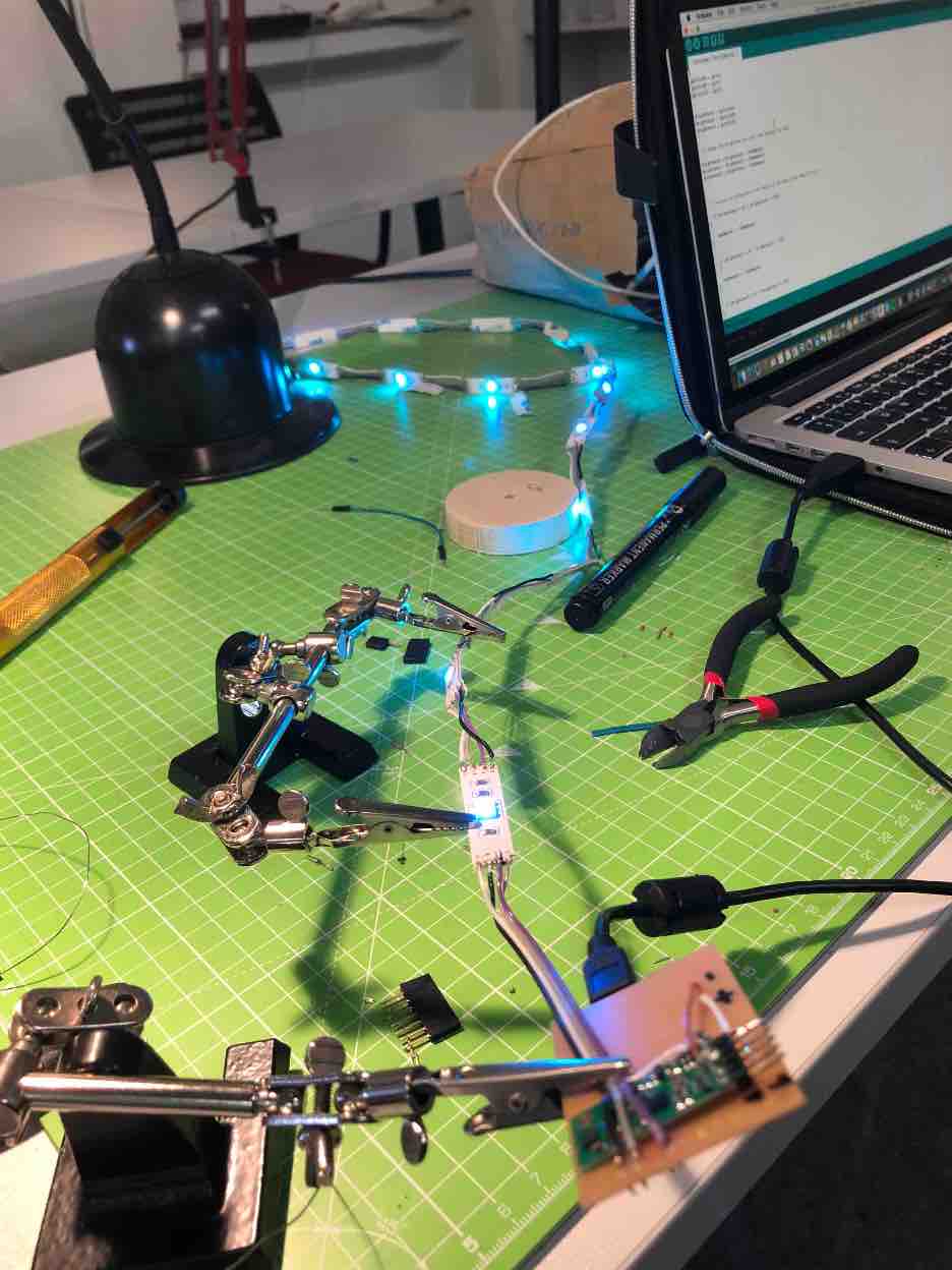
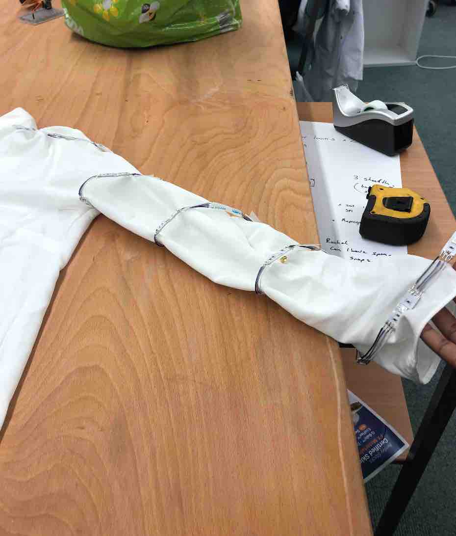
This was probably the MOST tedious task of them all. The first arm took forever to do. But in the process of making them I learnt better and more efficient ways to get it done, having made the second arm in a days worth of work.
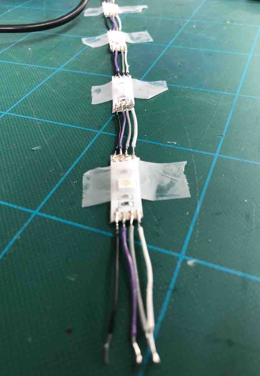
I discovered the best ways to solder the wires to make them stick on and not rip off like they were at the begining a lot - if I give the wire enough space, add on a blob of solder and stretch the solder from the LED to the wire, it became more durable. Another thing I learnt was how much time I saved by first cutting and separating the wires from each other, as well as taking off the plastic from the LEDs first, then soldering them all together. It meant that I wouldn't need to constantly stop one task to do the other or turn off the soldering iron to then separate the wires from each other. Basically I turned it into a full on factory process of doing things in groups instead of one at a time. I am not sure why it took me so long to think to do it but I got there in the end.
In oder to get an idea for how long the LED strip should be, I would check its length every so often to then also guesstimate how many more were required. I would do this by holding one end with my chin on my shoulder, then proceeding to wrap the LEDs around my arm, ensuring that there aren't too many LEDs but just enough so that no matter which way my arm faces when I wear them, a bunch will be visible.
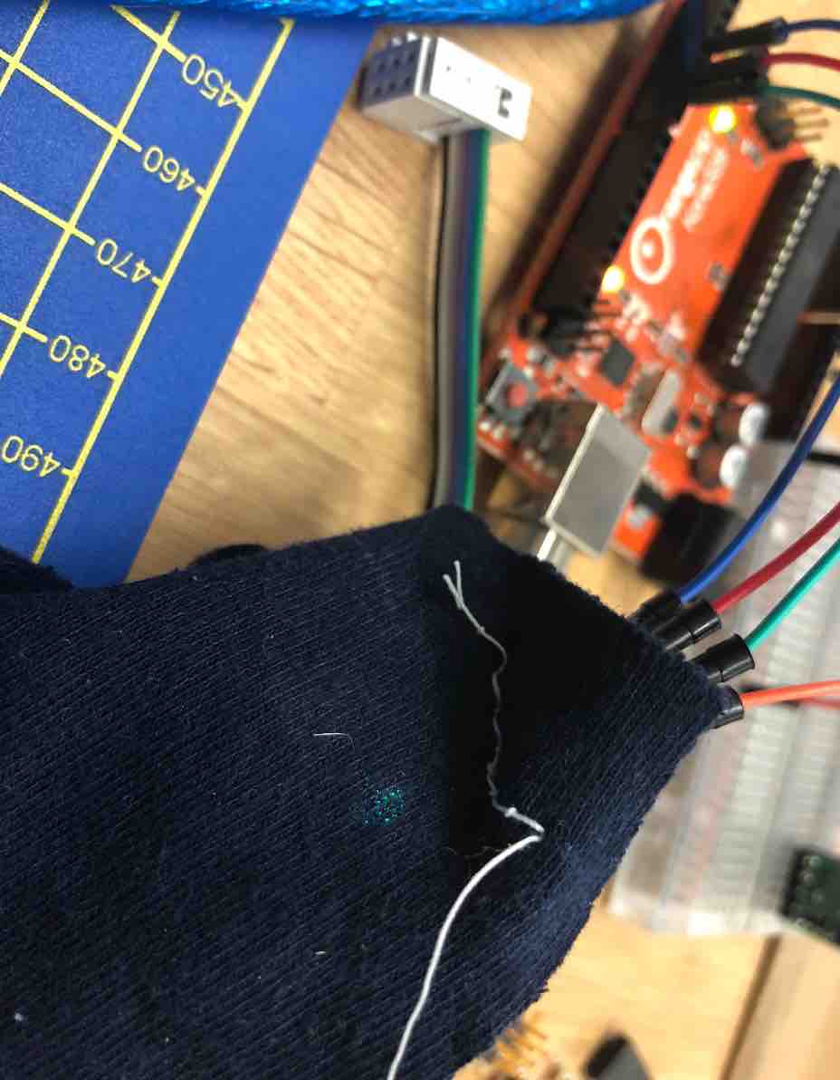
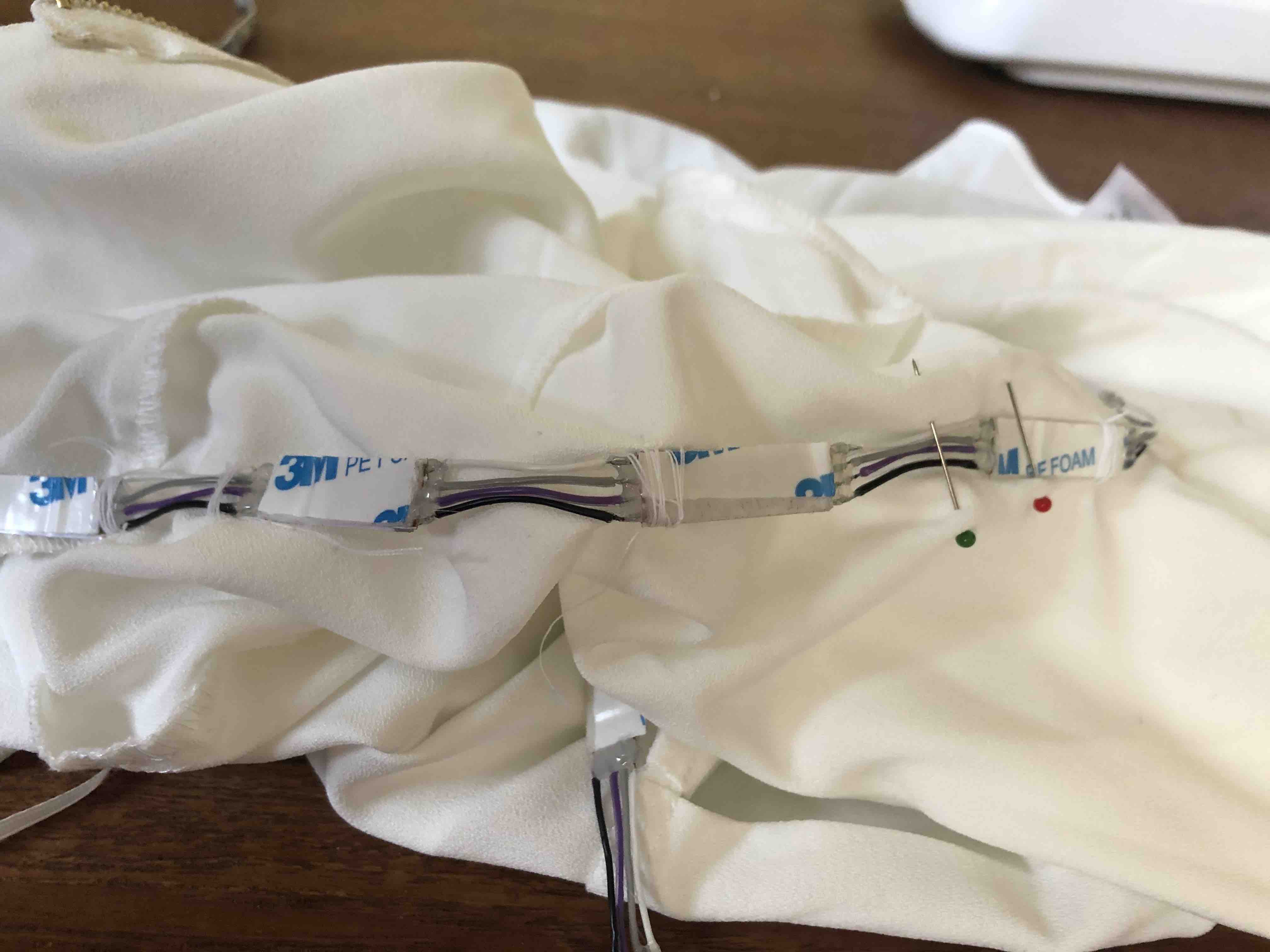
I did run into issues such as the LEDs being soldered on the wrong way round, or a wire breaking...but they were all fixable problems. Just annoying when they happened.
At the makerspace in Bonn, I was recommended to try using a glue gun to help ensure the LEDs wires did not break as they were quite fragile the way I made them. So I got to doing that before I sewed them onto my shirt. It turned out to be super helpful because as I was doing so, I instalty saw points that looked like they could break and after putting on the shirt and turning it inside out after finishing the sewing it made me realize how important that step was.
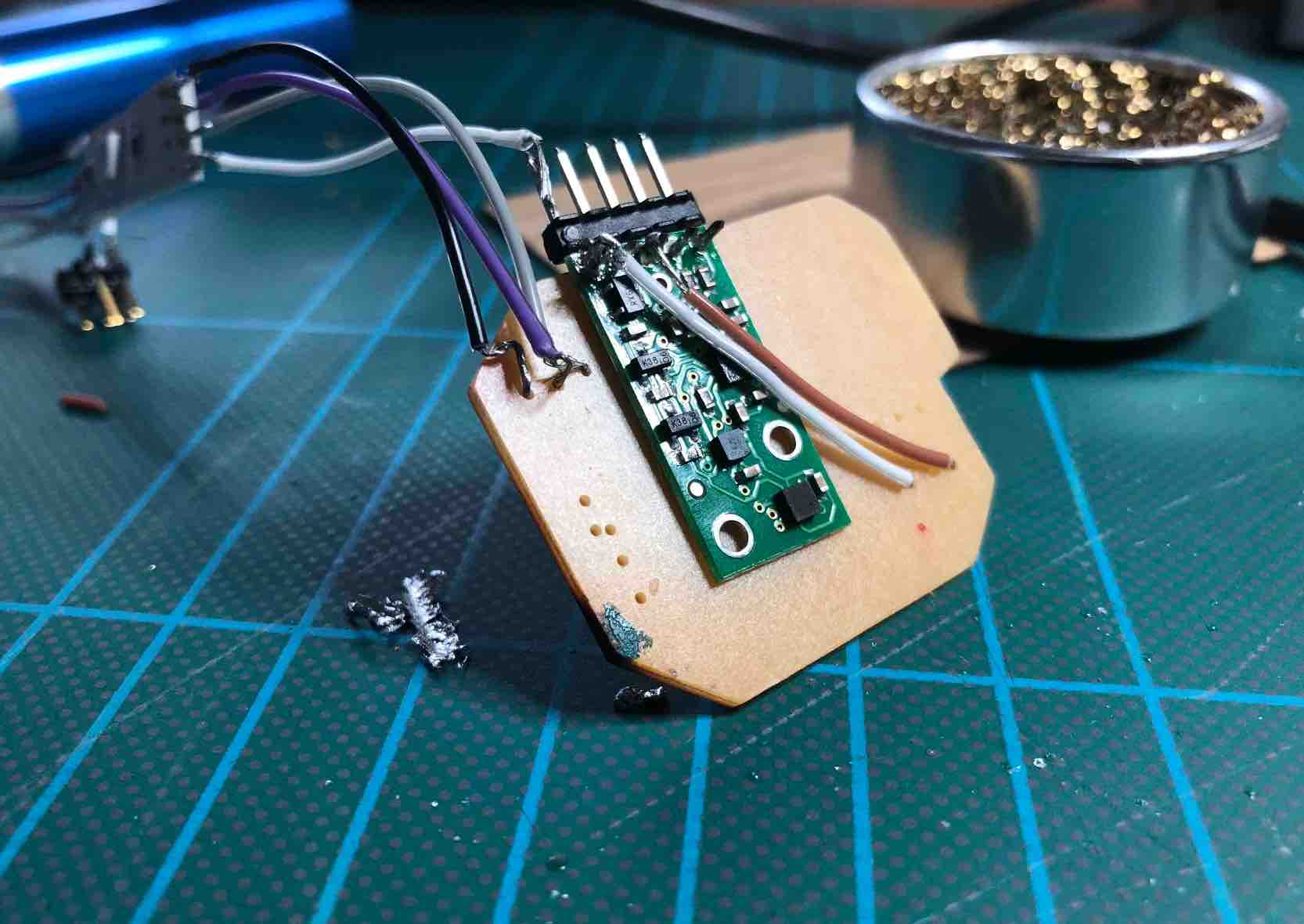
This. Was tricky. Because it required me to think twice as hard about best placement as well as how best to solder without breaking a trace. I eventually discovered I could just put it on the back of my board and solder it on that way, using the wires to sort of not only just connect but wrap it into place. I did this successfully on one board. But then my other board broke when I was trying to remove a component. So I had to use my old big bueno board as I no longer had access to a milling machine to make a new board! But at least I had something at my disposal. I visited a newly setup maker lab in Bonn, Germany, and there I met Stephan who graciously helped me to some of the tools the lab had to offer, along with some tips and tricks to make sure my soldered items remained soldered.
And thankfully, despite the boards being different, with a bit of creativity and flexibility on my side and the boards side, I got the bigger board soldered too!
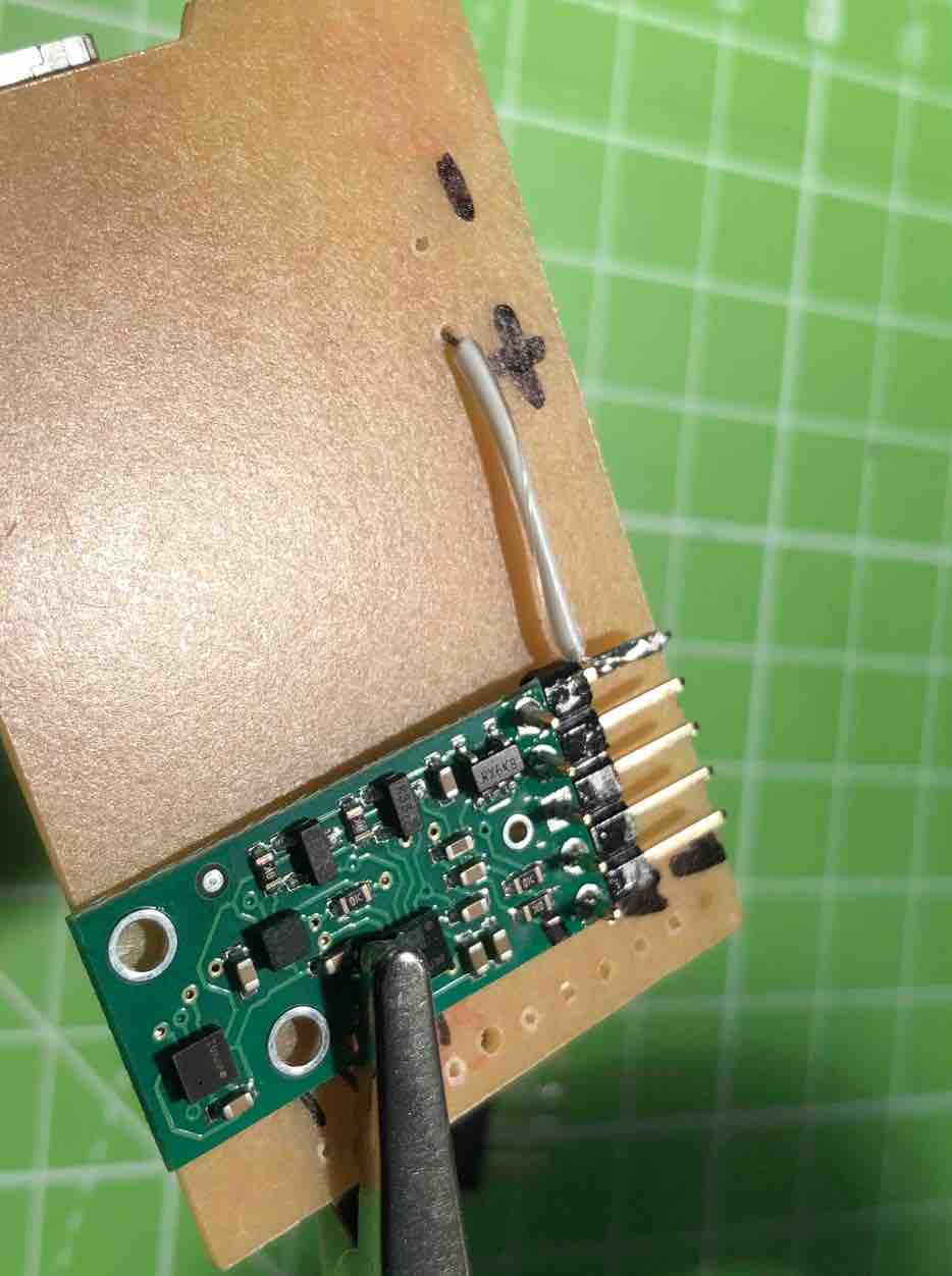
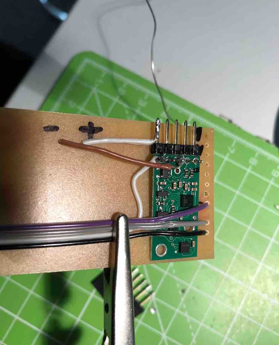
I had to take a picture of the gyroscope though to make sure I did not accidently solder things the wrong way around as the gyroscope was turned around so I could not read where things belonged. This was a super helpful thing to do! I think I had to use it 80% of the time to make sure things weren't going wrong or going wrong for the wrong reasons.
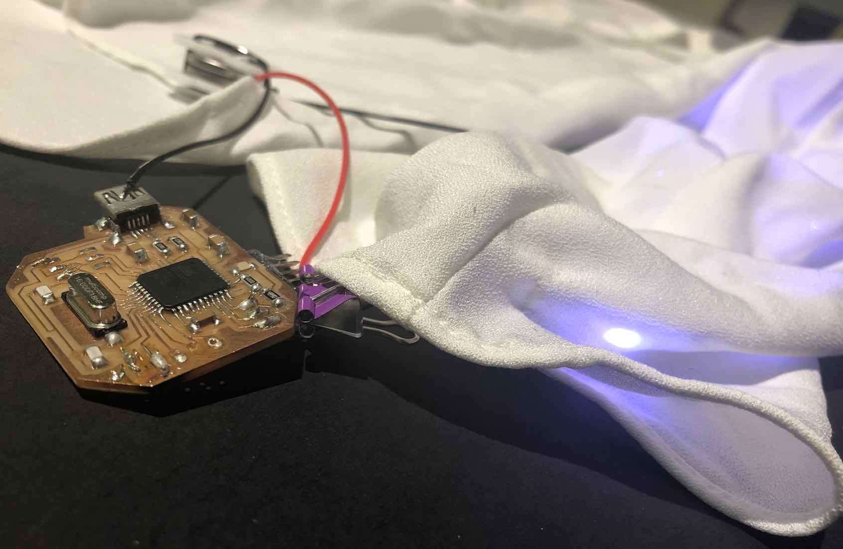
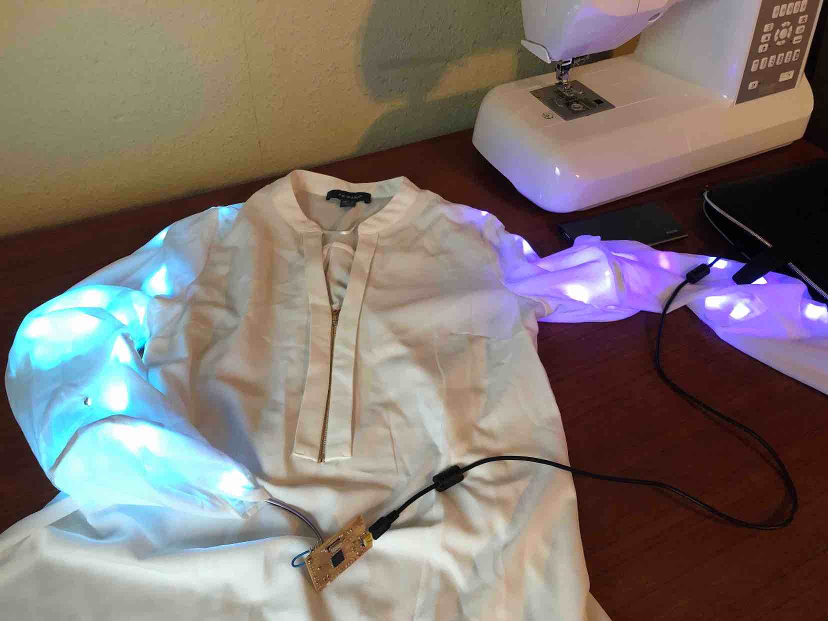
This is the final outcome of soldering the big board. It works :) And kind of looks like christmas lights (check out video if you aren't convinced)
Whilst I was milling my boards, I tested out our sewing machine. We are all assigned lab coats here, so using the SPAFF sewing achine we have, I took the color of my lab coat and began testing out the various stitch patterns.

After this, I tested to see if I could sew through my LED sections to see what options I had at my disposal in order to decide what method would be best to sew the circuit to my shirt. To test this I took off the tape off of the back of the LED, wetted it a bit to remove some of its stickyness to prevent the neddle getting stuck. I then used some pins to outline the area I wanted to sew so that I would not accidentally damage to LED or the resistor, crossed my fingers and began to sew.
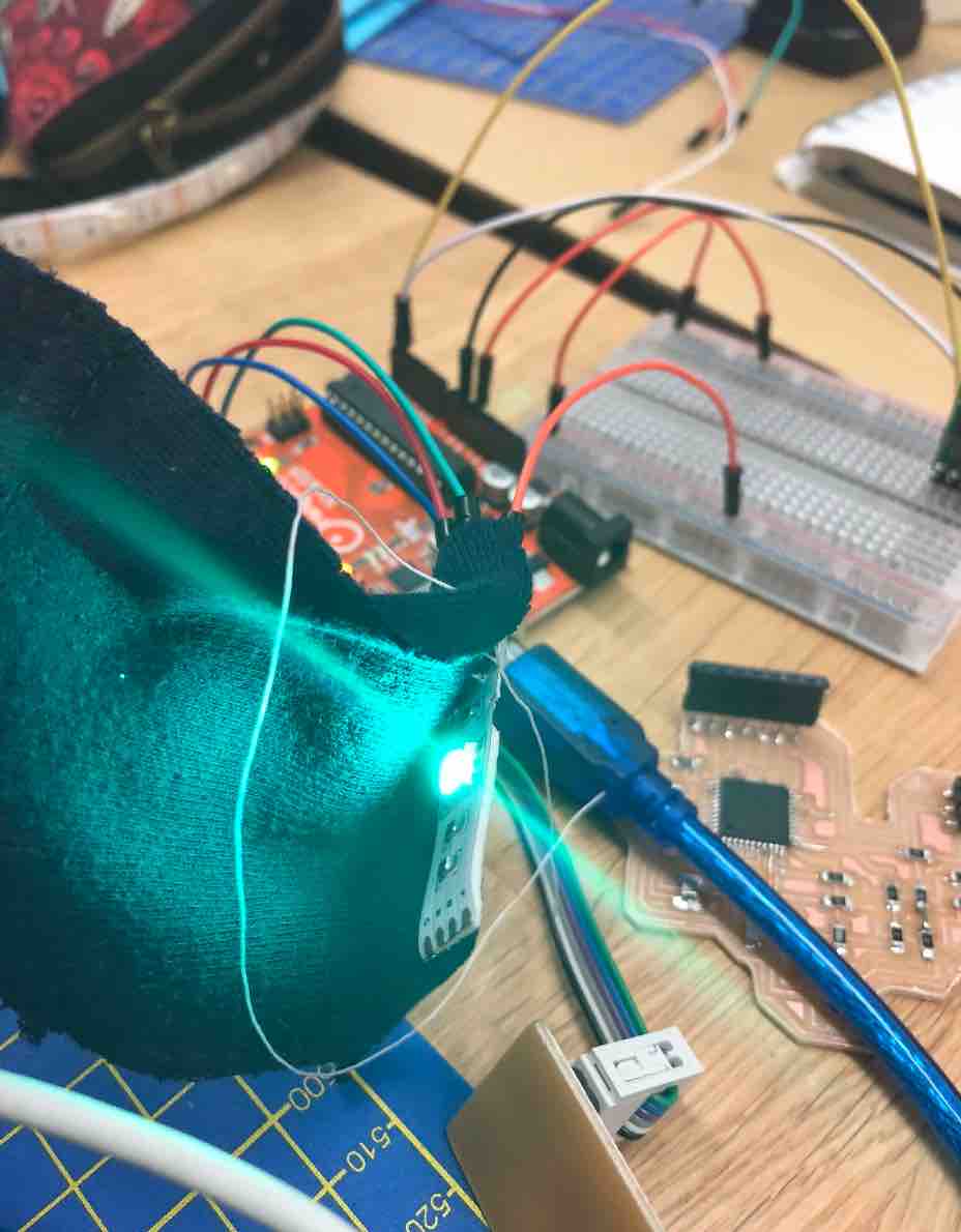
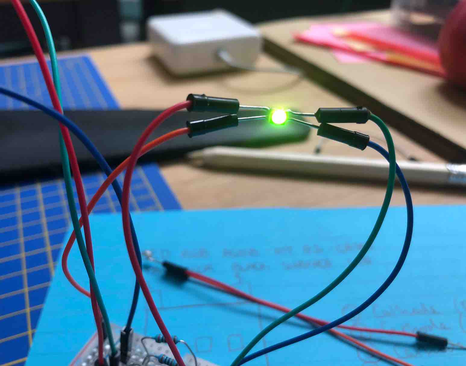
Luckily it wet smoothly and my LEDs are sew-able. The next step was to test if the LED was still functional. This I did by soldering jumper wires to the LED and hooking the LED up to the circuit previously setup. And yay! It worked just fine no issues. Rotated gyroscope and the LED responded accordingly, so this was great news.
To get a better idea of how long it should be length wise, I would solder a few LEDs, then hold them with my chin on my shoulder and wrap it around my arm, and if it it was too short still I would add more. Towards the end I guesstimated how many more I needed to do.
Then to double check but also have a look, I put it up against the shirt...
The next step was to then sew on the LEDs. Final stage!!!
It was as soon as I got here that I quickly realized using the Sewing machine was pointless because I wouldn't be able to actually sew on the LEDs without sewing the shirt shut! So I broke out my needle and thread and rolled up my sleeves and got to work doing it manually. I did have some difficulties.
To ensure they don't move I used a pin and sort of trapped the LEDs in their place. As for the spacing, this helped in turn. To help me when ti came to doing the middle bits as I couldn't fit in my arm to sew at the same time as holding the LED I was sewing in place, I used a bottle which i out through the arm. It helped also because then there is "meat" so when I am spacing it looks more realistic and I can see where I'm heading.
I noted that it was better when I sewed every other LED as then it would allow for more flexibility, less stiffness, which would mean easier to put on. It took time and patience but I got there in the end!
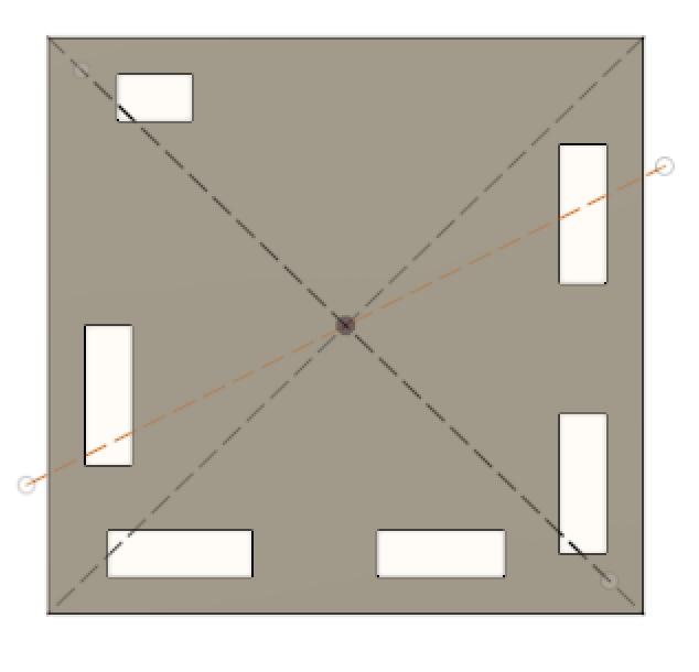
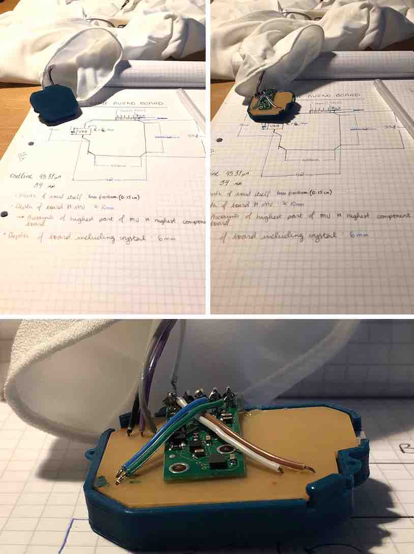
This, was a toughie. because I needed to take time to understand how best to make a case that could also later be removed if I wanted to change something on the board or even replace the board...anything. So it needed to be strong but not permanent.
I went online lookin for inspiration but everytime I found one it wasn't quite what I wanted despite how great some of them on instructables looked like, for example:
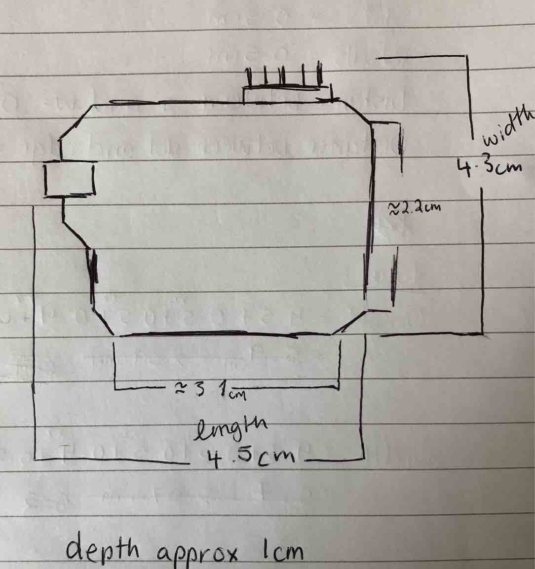
'3D Printed Modular Support (Case) for Arduino and Raspberry Pi - CustoBlocks'So to begin, I first made a sketch on paper of what I wanted the board case to look like, and then I went and implemented it a bit more looking at the bottom part. This case would be two parts together (how else of course would I get the board in?)
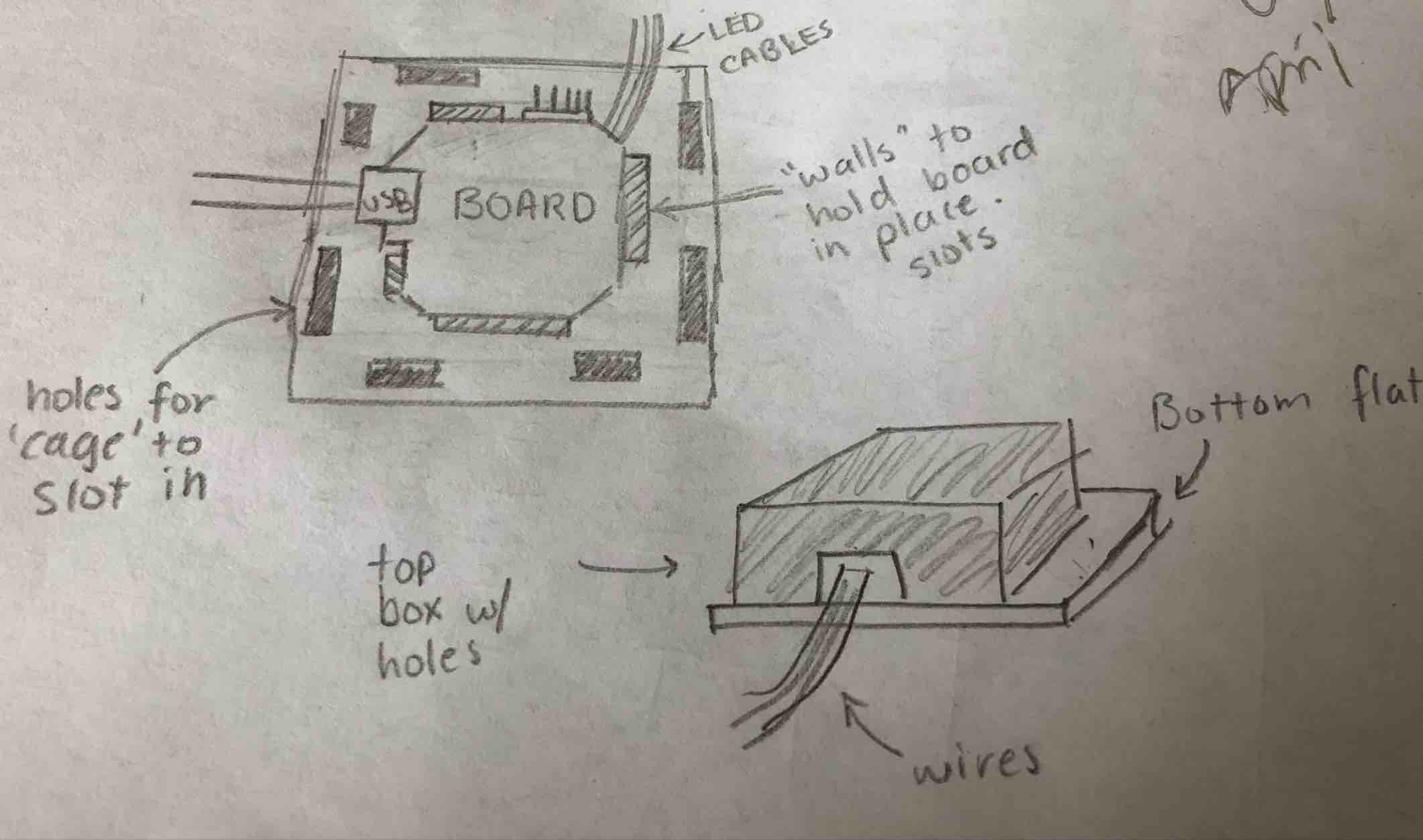
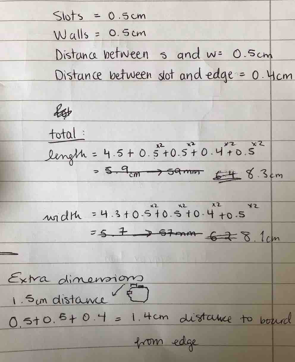
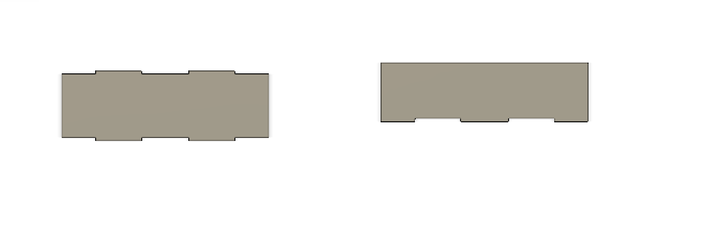
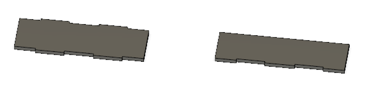
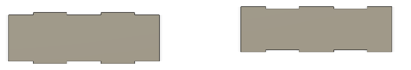
Next bit was taking measurements of the board. So I did a rough sketch of the board, measured the lengths of various parts of it and then wrote them all down. Then I looked into how much longer the flat surface part of the case needed to be in order to not only not be too big but also just about take the board and slot it in place so that it doesn't "jump around". So I set sizes for the slots, the walls, distances between parts, etc.
Then is was onto Fusion.
Then I moved onto creating.
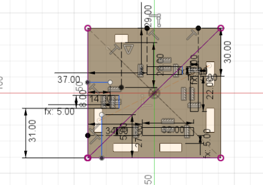
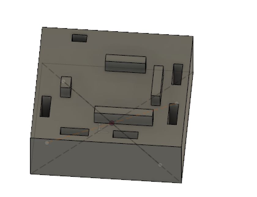
First I started with the bottom and used my table to make all the slots. I have to say once again that working in Fusion can be rough because what I see here is something massive but what it is isn't that big at all! But anyways, then I made the walls to hold the board. After that, I moved onto the top of the case. This one was easier to work with because I wasn't always confusing myself with numbers. It did take a bit of thinking though. In my image sketch above I made the box so that the top is not fully around the bottom so that is what I needed to do here. So I subtrace 0.4 from all sides because this was the "empty space" I wasn't going to be using (the space I had precalculated) and then used the previous sketch of the flat part of the case to work out where the legs of the top case needed to be by using the distance feature in Fusion. Then I would align them as needed and extruded them so that they would not go all the way through the slots but enough that they would go through them. This is in the hopes that they will be removable from the bottom but the wires can still pass through/slide through and I just sit the top on top. As I cannot reach the wires from the inside once the case is closed obviously.
Then I uploaded the file to Cura to make my gcode file to print. See week 5 - 3D Scanning and Printing on how to use Cura.
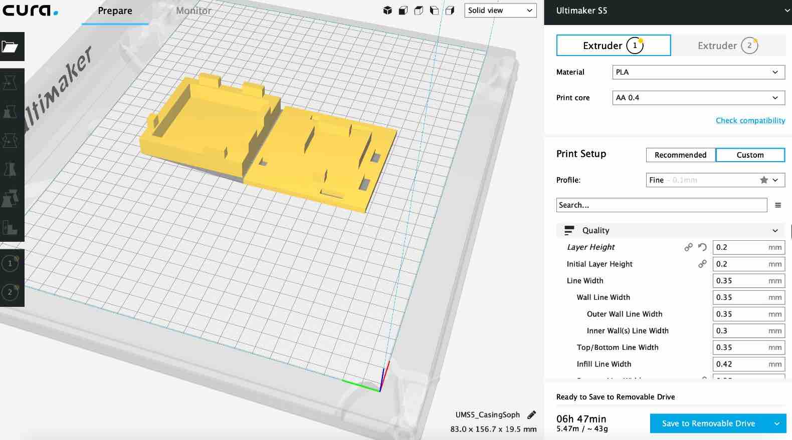
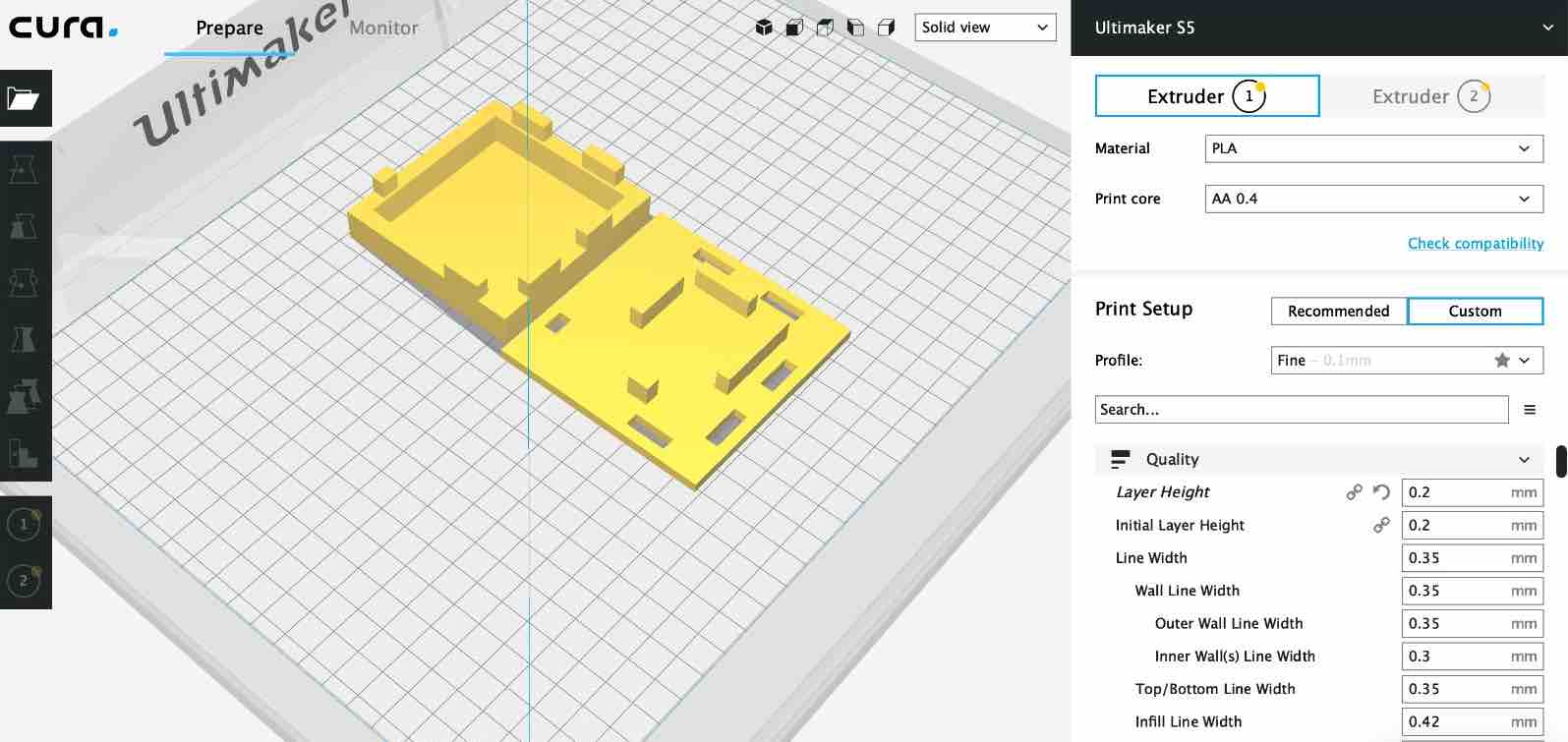
Then it was just a matter of going to the lab in Germany and printing it out.
At the moment the case is being printed so it will take some time, but man oh man check out the video below. The lab in Germany has this crazy sexy 3D printing machine, the UI not only looks amazing but is touch screen and it's got awesome features. The other one in Brighton though very cool too, took a while to heat up which would sometimes be frustrating when you wanted to print something in short time or something small, like when I was printing my servo head for machine week.
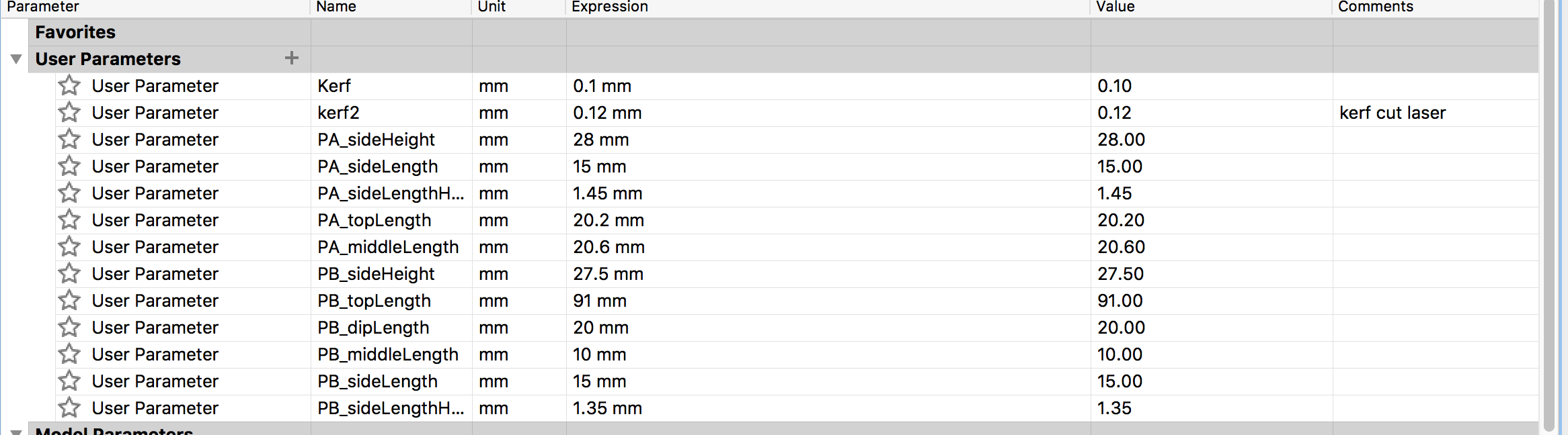
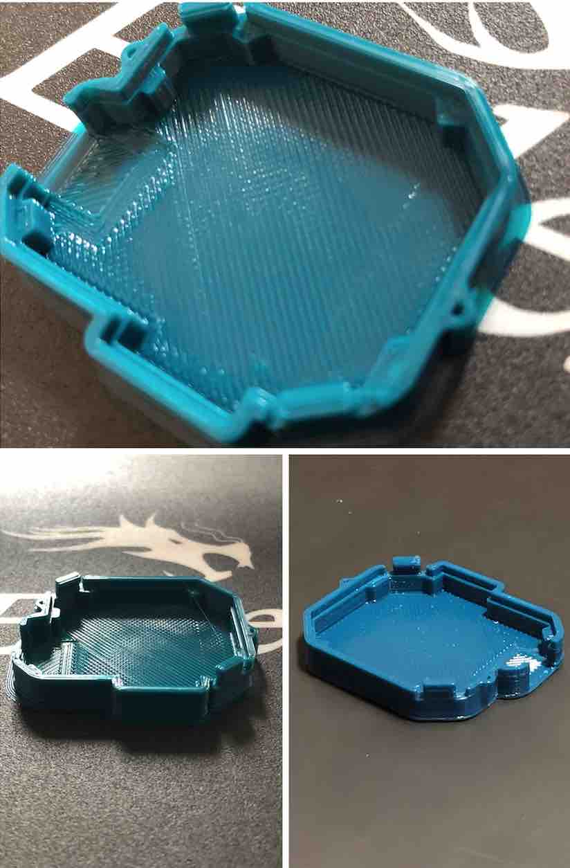
After realizing how gigantic my designed board case was, I quickly realized it was time for a redesign! I will admit fusion still confuses me between numbers, how it looks like on my screen and how it looks like in real life. For this, I had gone to Berlin to get Luiz's assistance and his connections. This time though I designed it in Rhino.
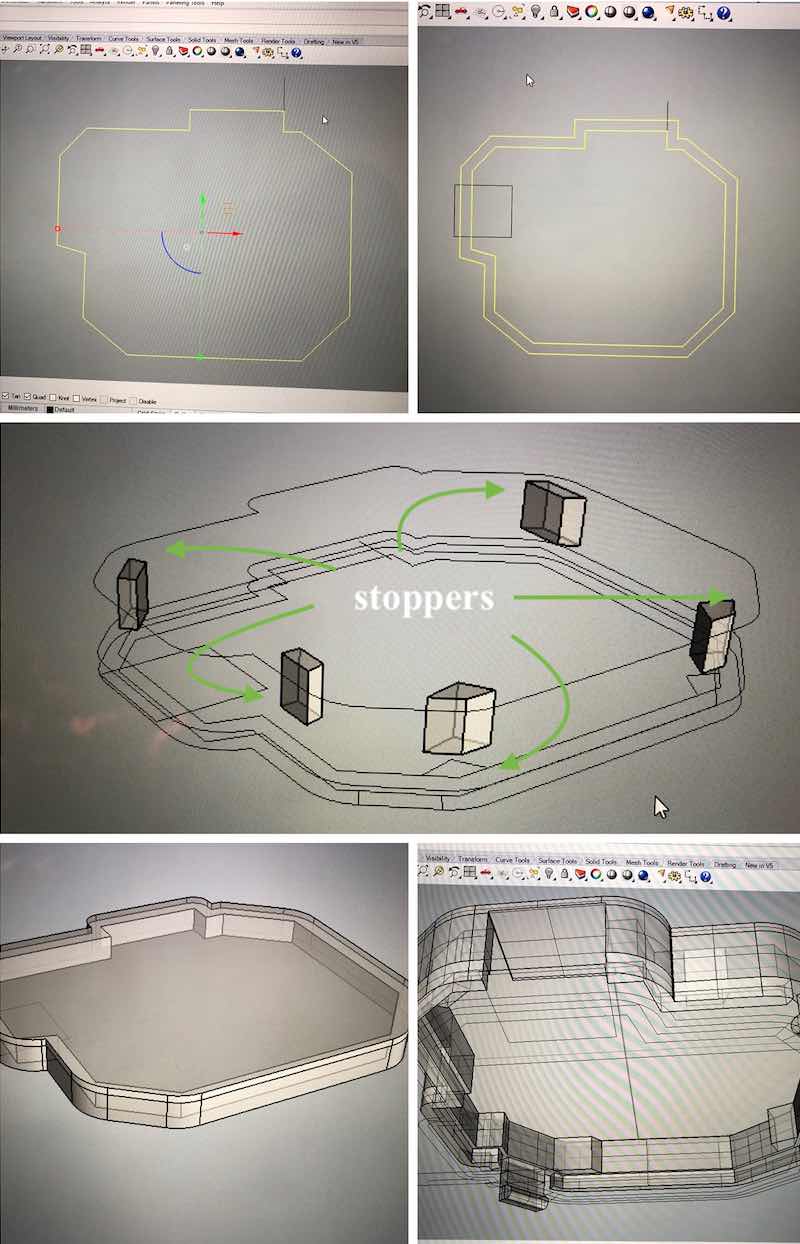
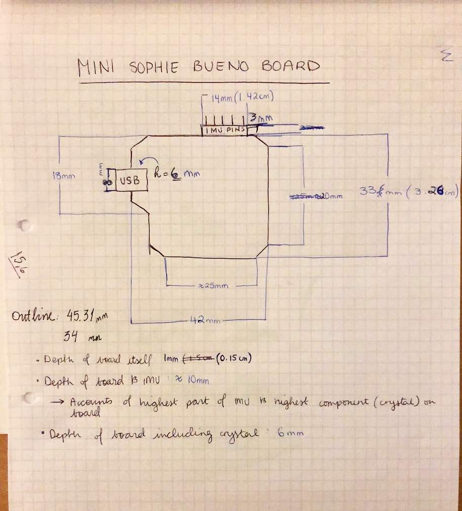
To do this, and avoid another mishap where I make another big board case, I decided to use the board I already had made! Seems simply right? Except last time I only measured the board I had infront of me. This time I measured them exact as possible with a calibar now in my possesion, as well as checking out what the boards actual listed dimensions were using my pngof my board's outline and Rhino. I also measured the size of the biggest components on my board, which where the crystal, USB and the IMU header pins, and documented them to then account for later on when designing the board. I then wrote these all down to use as a reference with a miniature sketch to accompany it. This allowed me to create a more accurate case (much more accurate than last time) and enabled me to find out how big or small to make holes to allow for the wires to pass through and where they needed to be located. I then used my drawn sketch and the measurements to allocae recorded measurements visually.
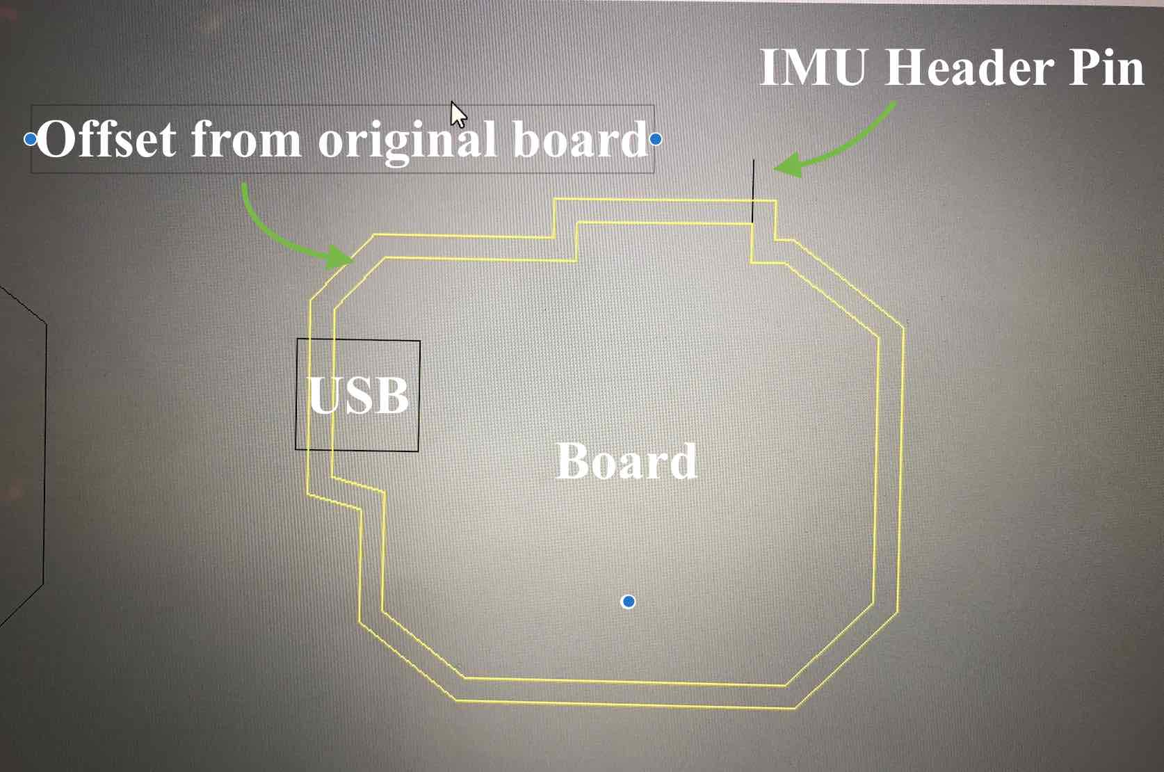
Once I allocated the USB's location and the IMU's header pin, I then added and offset from the original board to account for the material (fillament) and space for the board to fit.
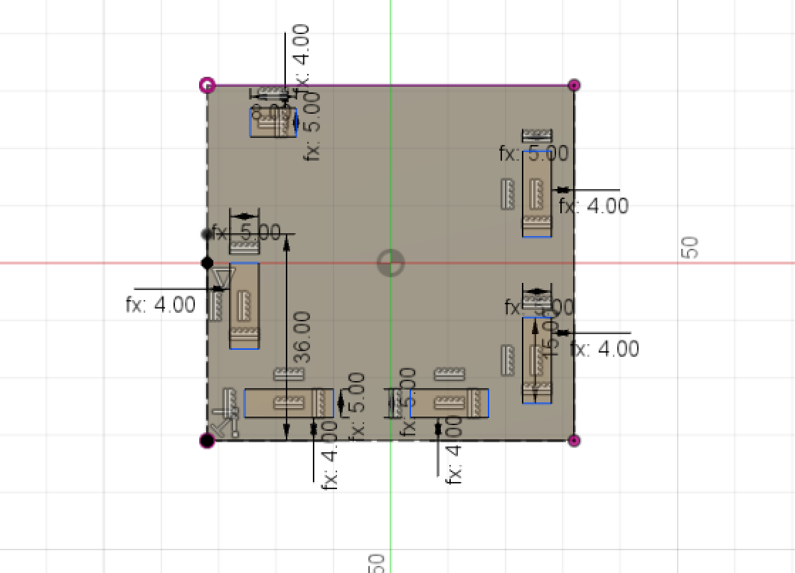
On 5 parts of the case there are stoppers (see collage image above). The stoppers help me so that the board does not "pass all the way through" but instead holds it in a certain place. Then I created the clamps which aimed to hold the board in place with the help of the stoppers. In order for the clamps to properly function as clamps, I made small snippets/holes next to them to allow for flexiblitiy and therefore also not make the casing permanent. This was done on both sides of the board then.
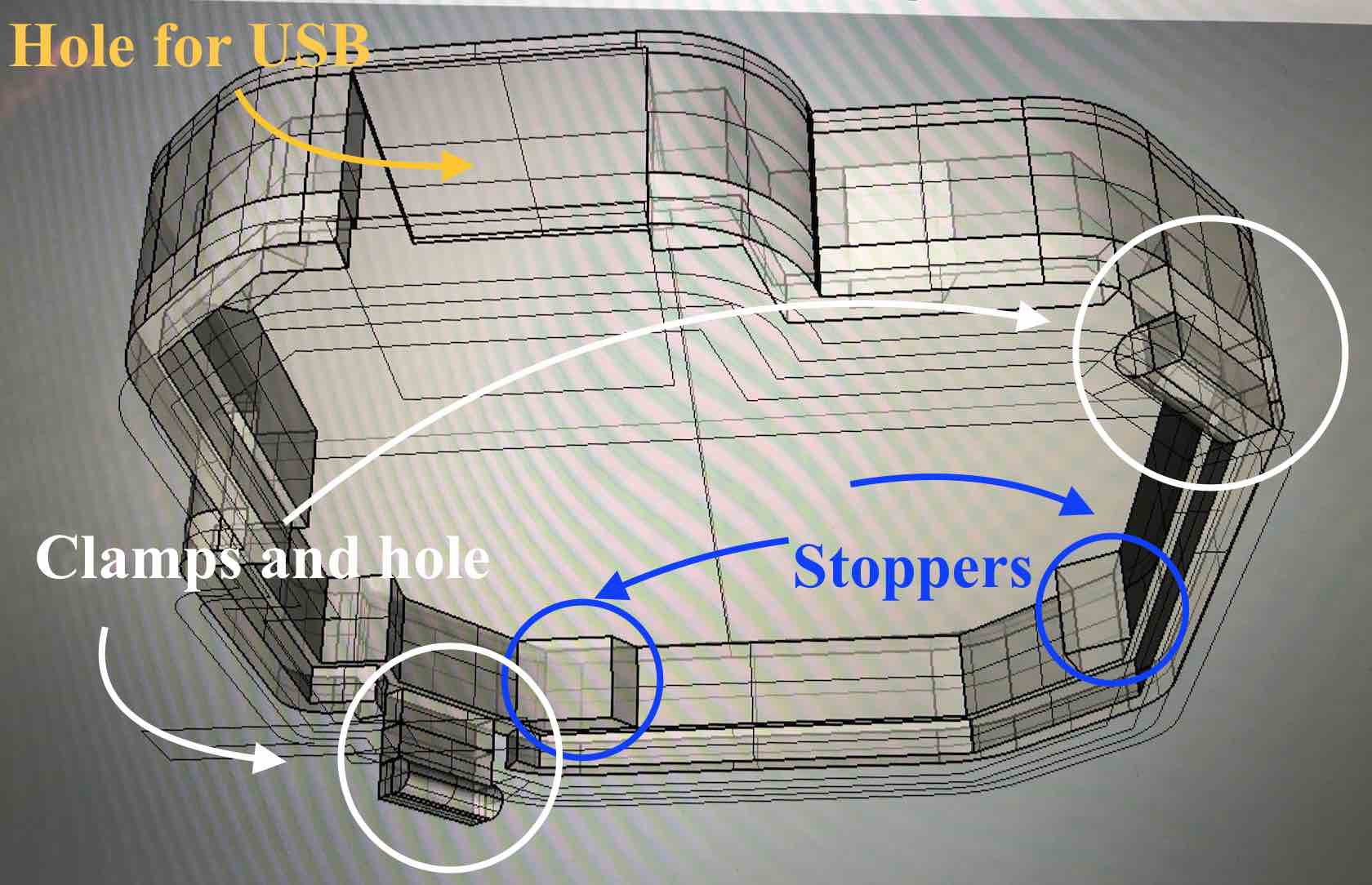
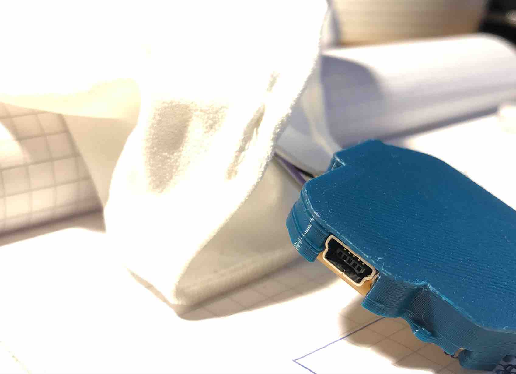
Usually the USB would be desoldered from the board but for the purposes of this project taking into account that I may and probably will want to change the code later on and need to reupload the the code (and that I don't have soldering equipment at hand at home). For consumer purposes though, this part would then be removed as it would be sold as a finished product. Though perhaps a nice touch to keep it open source would be to leave it to allow people to play with the code and create their own twists on the project.
As the previous case was much bigger than anticipated, the new idea or concept was to rid the previous concept of "locking" the board in a case, and do a cage where I "lock" or "click" the board into a case, and the "bottom" of the case would be the fabric. This is more ideal because of comfort. The previous design did not take in account the comfort of the project and its wearability, as well as how seemless it will appear. This one though does. Then with the addition of some holes around the case, it will allow me to sew on the case to the inside of my sleeve making it seemless and hidden (like a magic trick). Then because of the holes, I still allow access to the USB and the wires can still pass through with no issues, which is great because then it does not restrict the shirts flexibility in the wrist/forearm area.
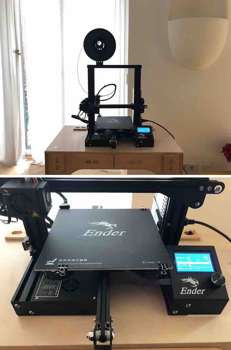
The 3D printer I used for this belongs to Luiz, he kindly allowed me to use it. It has the same functionality like the 3D printer I used in Brighton in 3D Printing and Design week which made it nice to use for me. The printer is called Ender-3. It's nozzle is 0.4mm.
This is a mini demonstration video to show you how to fit it on and how it looks like (as well as the ease for putting it on!)
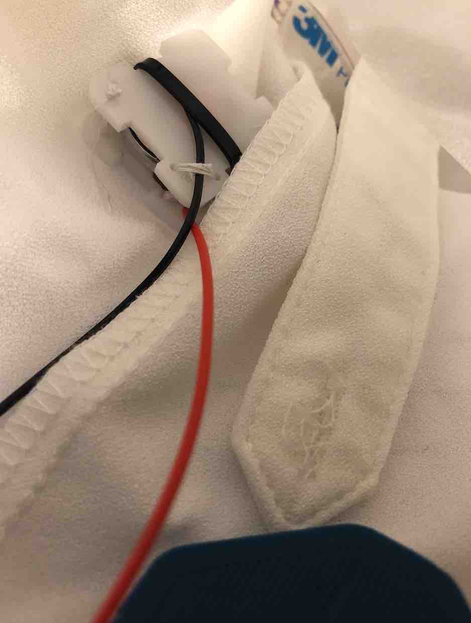
The next step was to ensure the string and needle could actually pass through their allocated holes (they did) and sew them o nto the shirt on the inside of the sleeve, which was a very fumbly job I will admit because of the fabric of my material being very flexible and soft. I made sure the wires of the LED weren't twisted first (to ensure it remained smooth and not bulky, but also to prevent breakage). It also needed to be as close to the endge of the sleeve as possible so that they gyroscope could then "record" as much data and arm movement as possible (as my wrist is the most flexible and movable part of my arm other than of course my hand), whilst still being far up in the sleeve that it would not show or pop out visually at any point when dancing.
Below is are some final looks of the board case before and attached to the board:
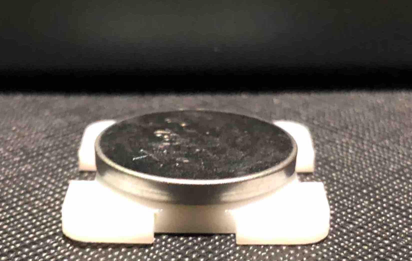
So here I made a battery holder. I was initially going to use a self made battery pack but then after looking at some tutorials online and seeing the potential dangers behind it and knowing my own capabilities as they are right now, I decided the safer thing to do was to use my mini battery packs.
Again it was a matter of taking it's dimensions down and then with the help of my previous projects making something that would hold it in place but then also be cute. However due to time and lack of a lab I am unable to make it into reality. BUT here's the sketch ;)
But then I realized that though it is made tight on the sides, it still won't prevent it from falling out ontop. So I made a top!
The next step is to make a bottom. Because I quickly realized that without one, the poor thing would just slide out...potentially. It also means updating the parameter list.
However, I don't have a very excellent history with that part because I can't quite calculate mathematically how it is supposed to work. And of course even more so without me being able to properly test it with the materials, I won't know for sure but this is what I should look like....
This was also done on my trip to Berlin. Here I got to see a new lab (another lab) - the Motion Lab! Luiz kindly took me there. It very much reminded me of Brighton because the people there seemed like they had formed a mini family, just that it was a much bigger lab space and there were companies within it...but that's all neither here nor there. They kindly allowed us to use their Laser Cutter and their soldering equipment whilst we spent the day there.
First things first, I decided what battery to use
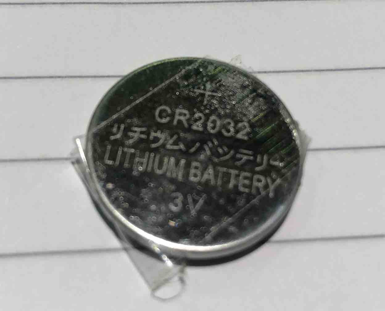
Then I took all it's measurements down for the designing process:
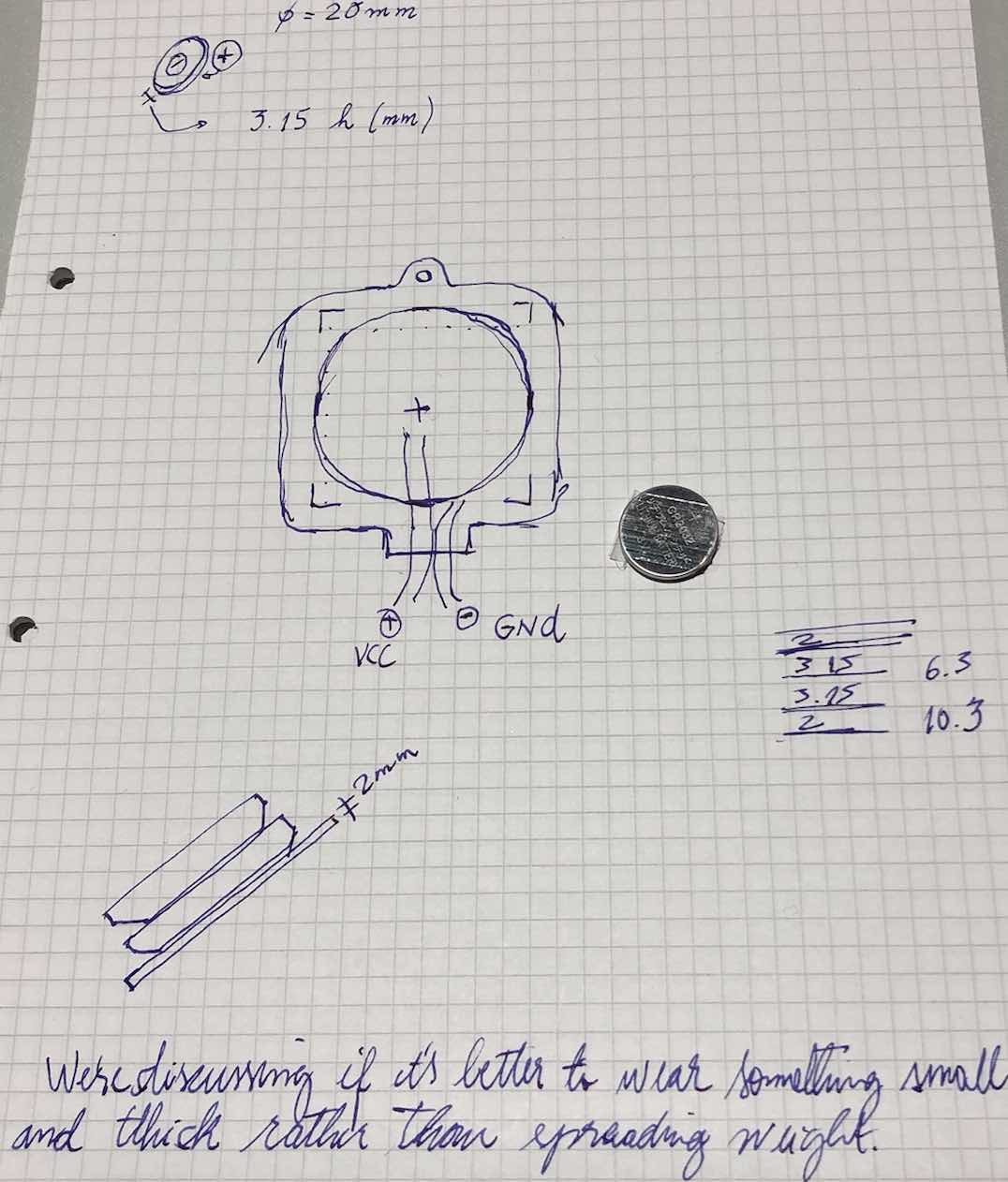
As described below, the battery holder features holes at the top left and bottom right to allow me to sew it onto my shirt secrurely. Then the bottom left spaced out holes were designed to then hold the wires coming out of the battery in place so they aren't fumbly later on and poking here and there under my shirt. Then as a cute little addition I added my name to it on the top right.
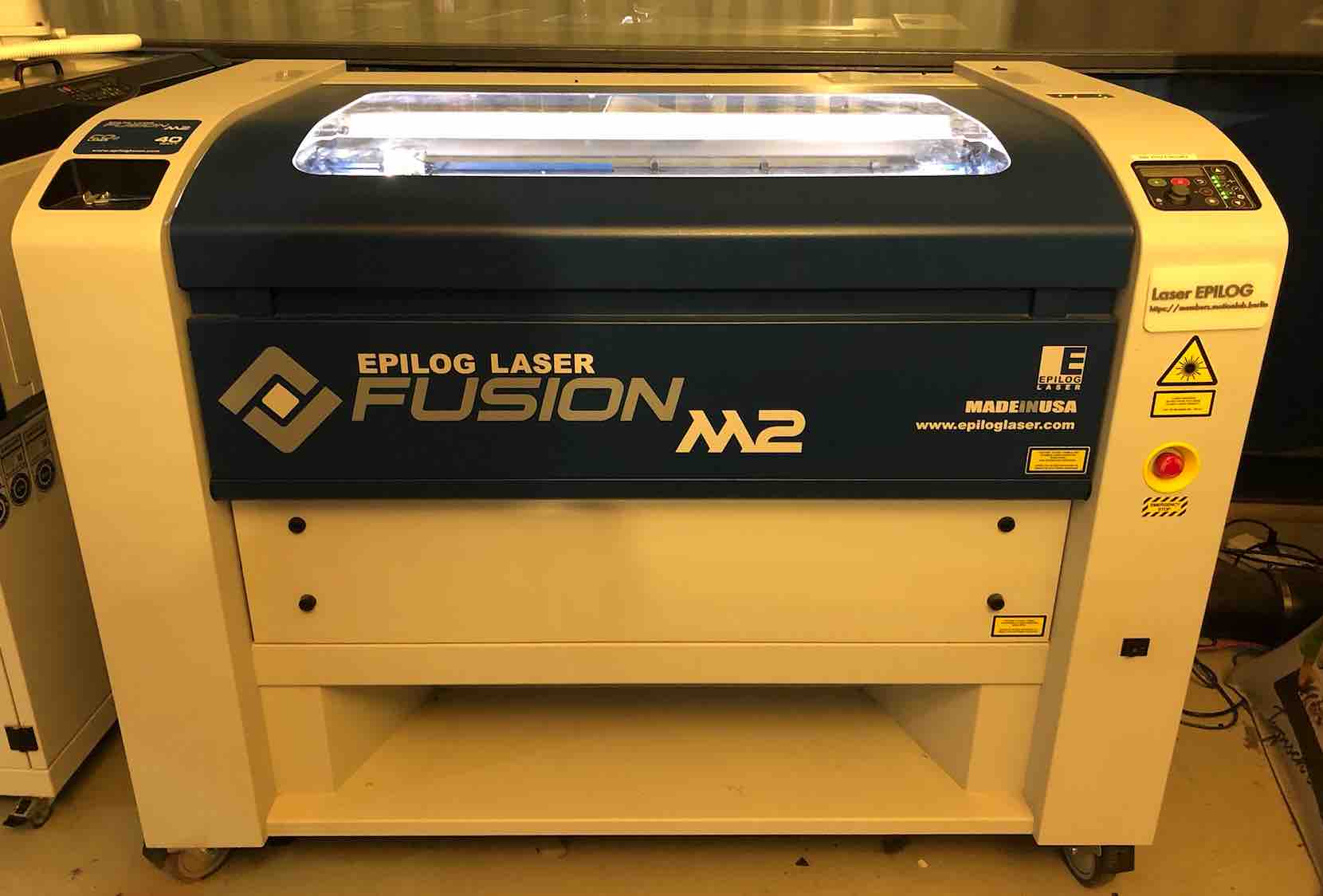
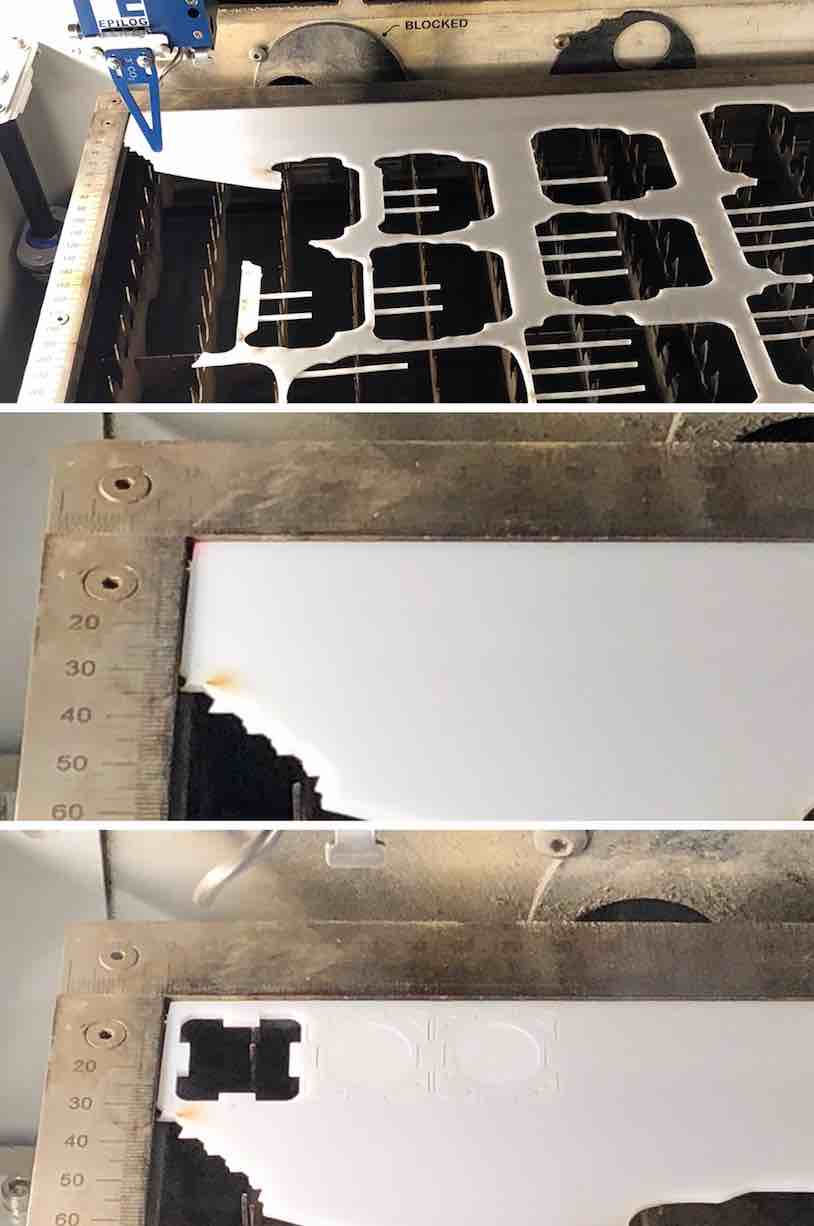
The next step was to laser cut it. This was a trial and trial process (meaning I would try one thing, then analyze how it needed to be improved and improved on it. To laser cut, I used the Epilog Laser Fusion M2 as pictured below.
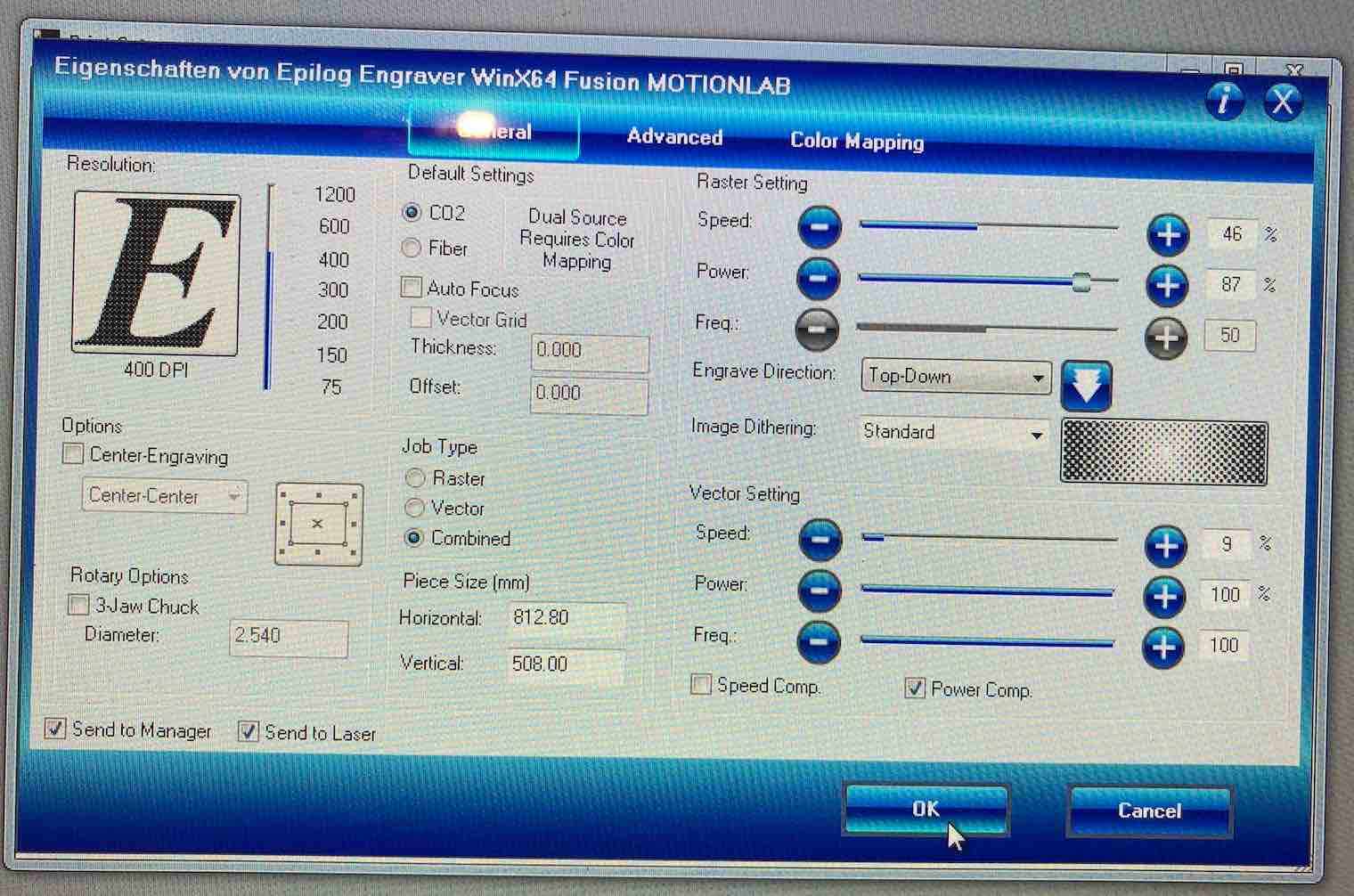
Initially we began cutting with the following settings...
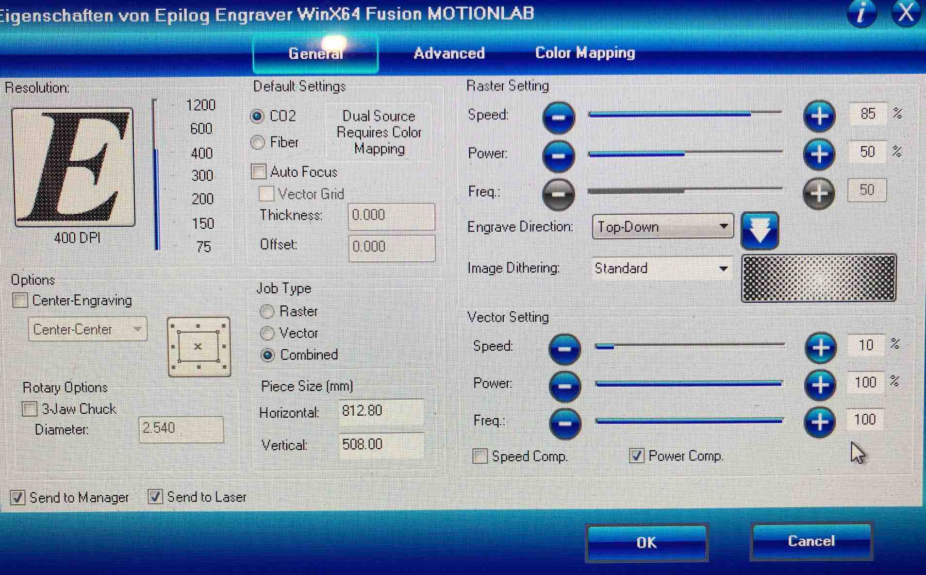
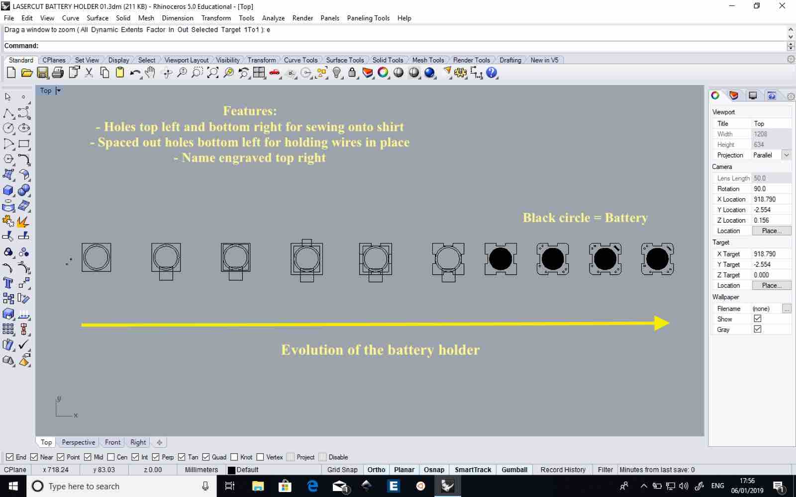
But then decided to alter them because the etched part where the battery cell was to go (the circular bit in the center) wasn't deep enough. So Luiz and I came up with a method which we built upon which was to laser cut it more than once (the etched part) then laser cut the whole thing. In the end we laser cut the etched parts 2 times before laser cutting the whole part which ended up working quite well. It was a delicate task because whilst the hole needs to be there, I did not want to cut through the battery holder else its purpose is then gone.
Holding them side by side in groups you can't tell the difference but as a evolution looking at all of them next to each other you can. The only other way to differintiate is when you run your nail over the etched battery cell place and the rest of the lasercut piece.
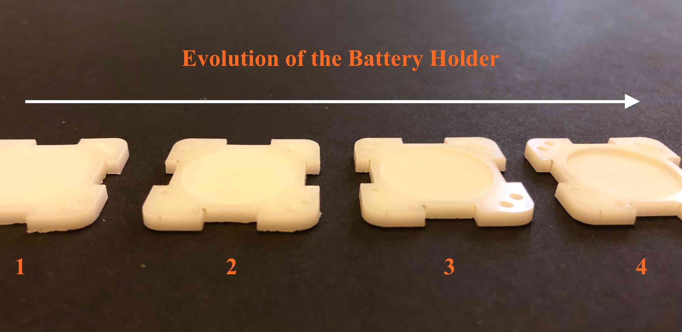
Ant this is what it looks like with the battery cell ontop...
I made two of them of course, one for the top theother for the bottom. Then, drilled a hole on the bottom side of the battery holder to allow me to access the wires to the battery cell without creating a short circuit.
Then, using the copper tape, made a pad on the battery holder, and I soldered one end of it to a black and then later another to a red wire to then create contact. I made sure to then make the solder as flat as possible with little to no bump so that it would not interfere with the battery cell when i put it ontop. The copper tape needed to be between the two wide holes without blocking them, and also so that I could then hold the wires down later.
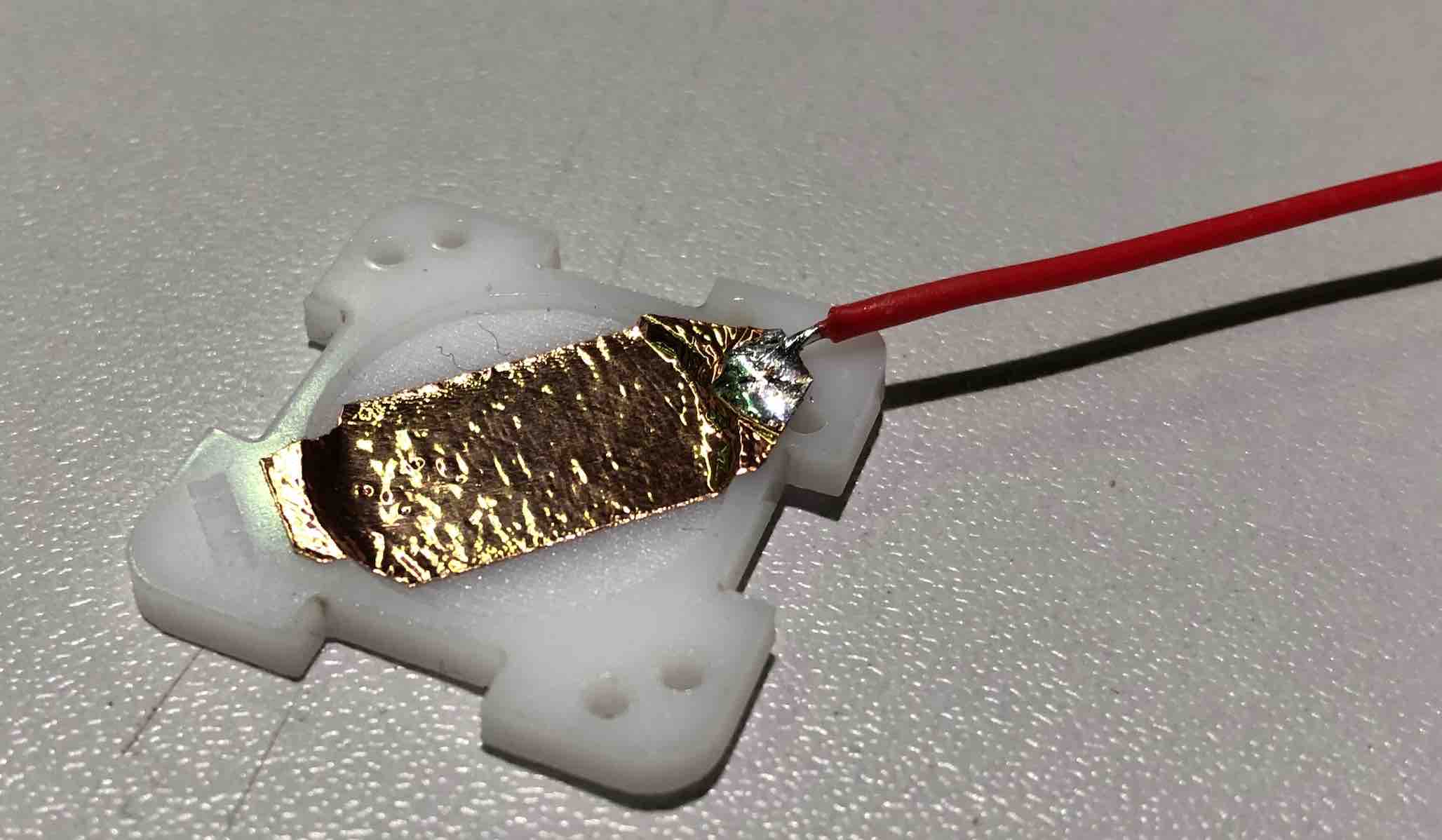
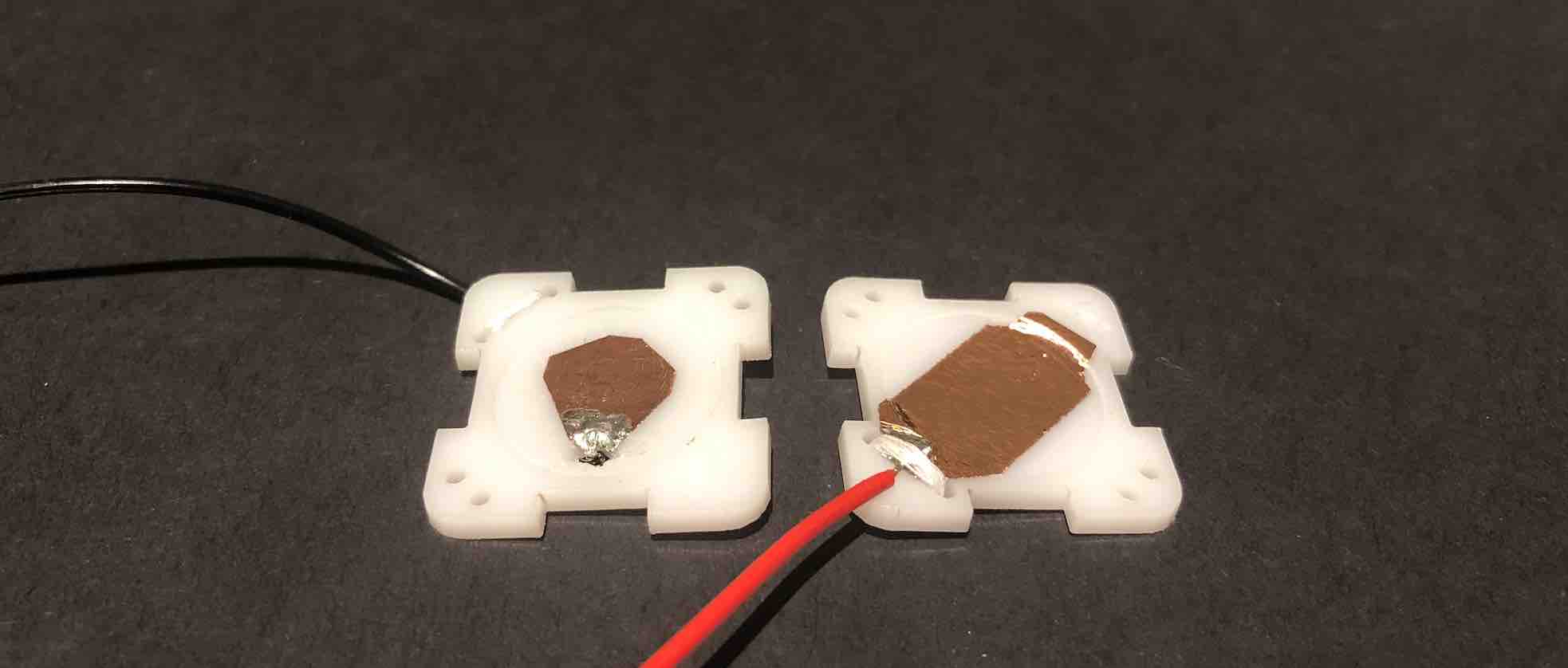
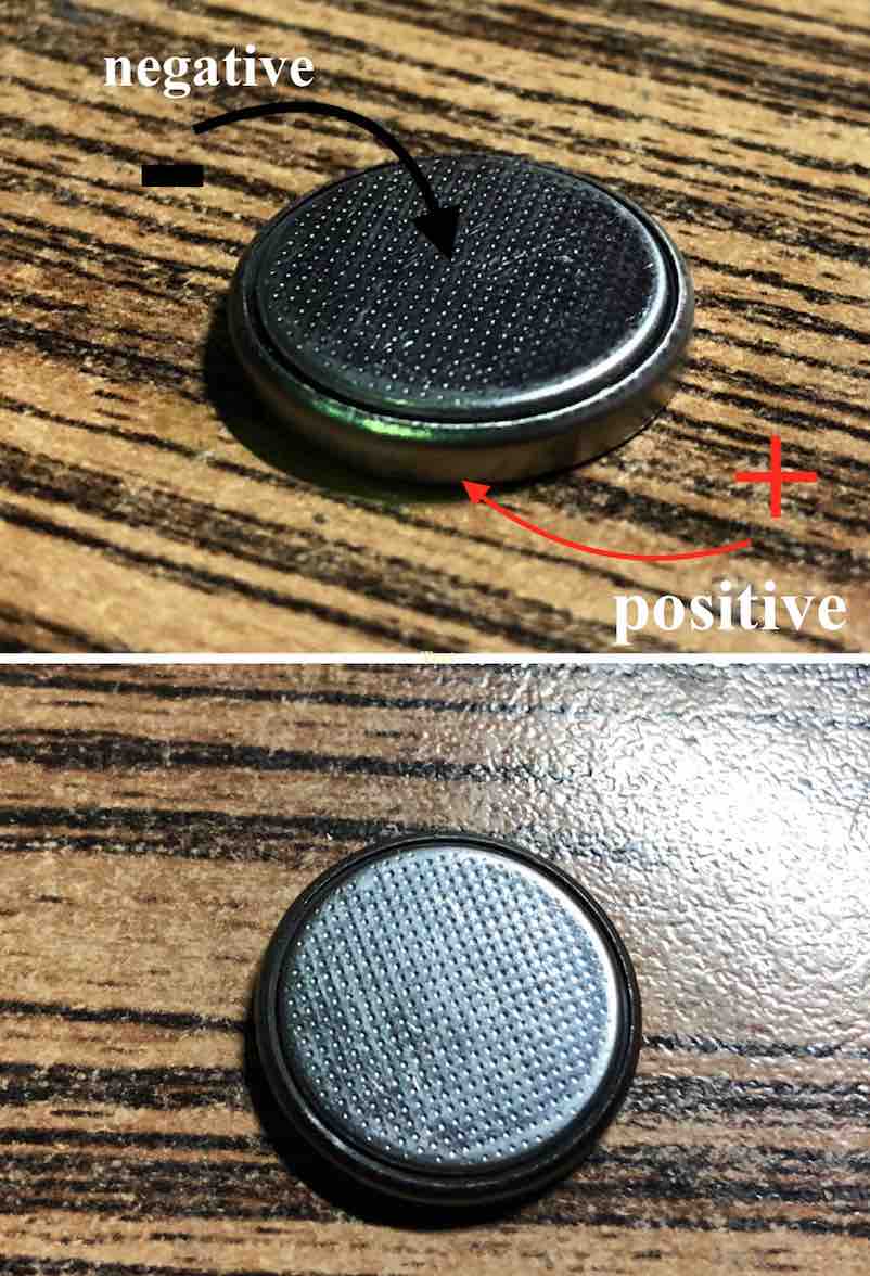
The tape for the negative side of the battery cell needs to be right in the center so that it has contact without creating a short circuit.But for the top everything is positive.
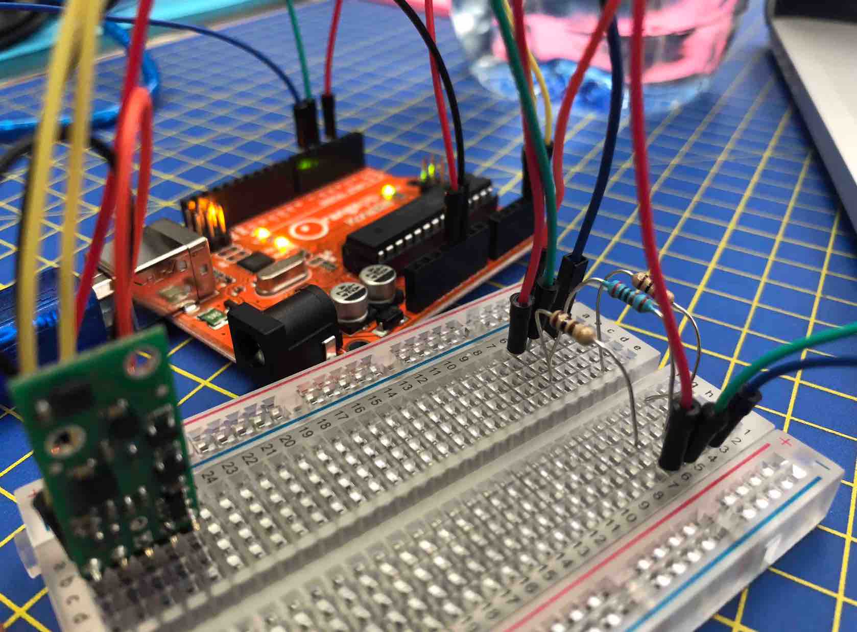
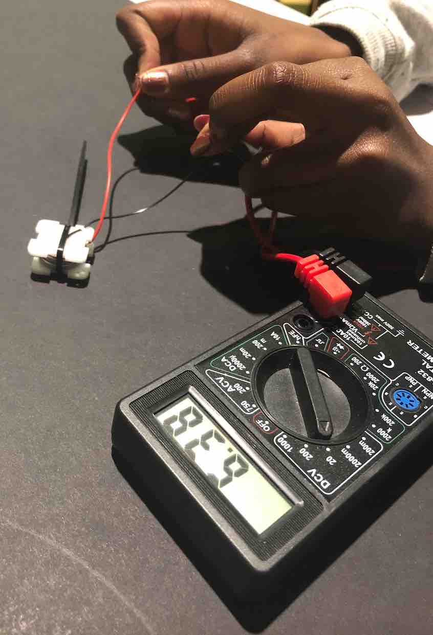
To ensure that they still worked after all this, I used a potentiometer. After seeing that it showed 6V, I then moved on to testing it out on my board which amazingly it worked and I was super excited.
One thing during this creative process that I had to debate was weather or not the battery cells should lie next to one another (meaning I would wear something thinner but longer) or if they should lie ontop of each other (meaning it would be thicker but smaller). The plan was to make protypes of both, however after seeing it made, I realied that having them ontop of eachother was not chunky in the slightest. Even after seeing how it was inside the shirt's sleeves.
Then it was time to sew it onto the shirt too. Again like the case, a fumble job. It does also make it harder because it is on the inside of the sleeve not the outside.
        /*

  The sensor outputs provided by the library are the raw

  16-bit values obtained by concatenating the 8-bit high and

  low accelerometer and gyro data registers. They can be

  converted to units of g and dps (degrees per second) using

  the conversion factors specified in the datasheet for your

  particular device and full scale setting (gain).


  Example: An LSM6DS33 gives an accelerometer Z axis reading

  of 16276 with its default full scale setting of +/- 2 g. The

  LA_So specification in the LSM6DS33 datasheet (page 11)

  states a conversion factor of 0.061 mg/LSB (least

  significant bit) at this FS setting, so the raw reading of

  16276 corresponds to 16276 * 0.061 = 992.8 mg = 0.9928 g.

*/


#include <Wire.h>

#include <LSM6.h>


int ledR = 9;           // the PWM pin the LED is attached to

int ledG = 6;           // the PWM pin the LED is attached to

int ledB = 10;           // the PWM pin the LED is attached to


int gyro2LedX = 0;  //Red being fed into gyroX r
int gyro2LedY = 0; //Green being fed into gyroY g
int gyro2LedZ = 0; //Blue being fed into gyroZ b


int brightnessX = 0; //brightness for X
int brightnessY = 0; //brightness for Y
int brightnessZ = 0; //brightness for Z

int fadeAmount = 45;    // how many points to fade the LED by


LSM6 imu;


char report[80]; //


void setup()

{


  pinMode(ledR, OUTPUT);

  pinMode(ledG, OUTPUT);

  pinMode(ledB, OUTPUT);


  // pinMode(ledR_a, OUTPUT);
  // pinMode(ledB_a, OUTPUT);


  Serial.begin(9600);

  Wire.begin();


  if (!imu.init())

  {

    Serial.println("Failed to detect and initialize IMU!");

    while (1);

  } else {
    Serial.println("IMU OK!");

  }

  imu.enableDefault();

}


void loop()

{

  imu.read();


  int gyroX = imu.a.x;

  int gyroY = imu.a.y;

  int gyroZ = imu.a.z;


  int gyroX_a = imu.a.x;
  int gyroY_a = imu.a.y;
  int gyroZ_a = imu.a.z;


  gyroX = map(gyroX, -20000, 20000, 0, 255);

  gyroY = map(gyroY, -20000, 20000, 0, 255);

  gyroZ = map(gyroZ, -20000, 20000, 0, 255);


  //gyroX_a = map(gyroX_a, -20000, 20000, 0, 255);

  //gyroY_a = map(gyroY_a, -20000, 20000, 0, 255);

  //gyroZ_a = map(gyroZ_a, -20000, 20000, 0, 255);


  // Serial.println((imu.a.x), (imu.a.y), (imu.a.z));

  Serial.print("GyroX:");
  Serial.println(gyroX);

  Serial.print("GyroY:");
  Serial.println(gyroY);

  Serial.print("GyroZ:");
  Serial.println(gyroZ);


  /*

    Serial.print("GyroX_a:");
    Serial.println(gyroX_a);

    Serial.print("GyroY_a:");
    Serial.println(gyroY_a);

    Serial.print("GyroZ_a:");
    Serial.println(gyroZ_a);
  */


  gyro2LedX = gyroX;
  gyro2LedY = gyroY;
  gyro2LedZ = gyroZ;


  brightnessX = gyro2LedX;
  brightnessY = gyro2LedY;
  brightnessZ = gyro2LedZ;


  // change the brightness for next time through the loop:

  brightnessX = brightnessX + fadeAmount;
  brightnessY = brightnessY + fadeAmount;
  brightnessZ = brightnessZ + fadeAmount;


  // reverse the direction of the fading at the ends of the fade for X,Y,Z:

  if (brightnessX <= 0 || brightnessX >= 255)
  {

    fadeAmount = -fadeAmount;
  }


  if (brightnessY <= 0 || brightnessY >= 255)
  {

    fadeAmount = -fadeAmount;
  }


  if (brightnessZ <= 0 || brightnessZ >= 255)
  {

    fadeAmount = -fadeAmount;
  }


  // set the brightness of pin 9, 6, 10:

  analogWrite(ledR, brightnessX);

  analogWrite(ledG, brightnessY);

  analogWrite(ledB, brightnessZ);


  //      analogWrite(ledR_a, gyroX_a);

  //  analogWrite(ledB_a, gyroY_a);

  //   analogWrite(ledR_a, gyroZ_a);


  delay(150);


  void red();
  {
    gyro2LedX = 255;
    gyro2LedY = 0;
    gyro2LedZ = 0;
  }

  void green();
  {
    gyro2LedX = 0;
    gyro2LedY = 255;
    gyro2LedZ = 0;
  }

  void blue();
  {
    gyro2LedX = 0;
    gyro2LedY = 0;
    gyro2LedZ = 255;
  }

  void purple();
  {
    gyro2LedX = 141;
    gyro2LedY = 62;
    gyro2LedZ = 255;
  }

  void yellow();
  {
    gyro2LedX = 232;
    gyro2LedY = 219;
    gyro2LedZ = 64;
  }

  void aqua();
  {
    gyro2LedX = 75;
    gyro2LedY = 255;
    gyro2LedZ = 250;
  }

  void orange();
  {
    gyro2LedX = 255;
    gyro2LedY = 83;
    gyro2LedZ = 13;
  }

  void white();
  {
    gyro2LedX = 0;
    gyro2LedY = 0;
    gyro2LedZ = 0;
  }

}

Sophie Kiarie, Fab Academy 2018
Here are is the LED off me...
..and a video to take you through the last hurdle and results of my project.
I think this was worth all the stress it caused my poor little heart. BECAUSE IT WAS COOL! I am so glad I made it happen! It would be cool to have this expand so that it almost becomes a sort of bodysuit. However, I will admit it was a bit uncomfortable to wear because of all the LEDs around my arms poking me. So something I'd like to work on would be to make it wear-friendly. Other big things I want to work on is a glove that one can wear where the board and a powersupply of sorts would be kept. I had to hold my board to have the gyroscope detect more movement as the hand is where the most movement would be recorded. I did consider having a little pouch at the of the shirt, but decided not to because the shirts sleeves were very fine and didn't quite reach my wrists so perhaps with a different shirt. Another thing is the power source. I would want to have had more time to experiment with different methods to power my shirt without needing to be connected to my computer. I tried using my powerbank, which was fully loaded, but it wasn't enough power. Having cables when dancing restricts movement so that it a big thing I would want to work on. I would also like to then work on the code to have more control over the LEDs. One thing I would love to look into is having is have 2 settings that can be changed from the board without having to upload things again:
It would also be nice to work on having a wider range of colors but I believe for this I would need better LEDs as mine were cheap ones off of Amazon. But this would make performances more entertaining to watch.
Other than that though, I think this was pretty succesful. I got a shirt than shows beautiful LEDs controlled by my gyroscope and the craftsmanship looks excellent! I made sure to use white thread when I was sewing that matched the shirt. Having the LEDs on the inside instead of outside was a great idea.
Special friggen thanks to my parents for supporting me and funding all my stays and trips in Brighton and to Brighton to allow me to finish my project.
To Kelly Snook for her undeniable support 100% and providing me with the opportunity to go and be part of the lab every single time without even batting and eye!
To Luiz for being an amazing instructor and friend and staying late nights and early mornings with me to help me finish my project, and always having faith and always pushing me. Thank you dude for never giving up on me! You are a "great instructor"! ;)
To Michael for being so supportive when I felt like I could not move on, and for enriching my knowledge with HTML and CSS to a level I would not have previously imagined I would be capable of achieving
To Kyle for helping me with the code when I was still a rookie and teaching me instead of just giving me all the answeres so I can get there on me own.
To Bas for being an incredibly cool and benevolent Global Evaluator :)
To Wendy for being able to step in and point out things I had missed out and being a very kind Global Evaluator especially on such short notice!
And lastly...Neil for being well....awesome :D