final project -- about me -- weekly assignments -- fab academy
Overkill for a Clock: Electronics
Since I originally started out building a motorized SMD placer, the electronics were planned for that as well - With their scope even widened a bit to get a universal set of motor controllers, a central brain to do the realtime tasks and possibly other I/O-units for stuff like a manual control joystick, vacuum pumps or other things.
The development and build of the brain and motor boards can be read up (in chronological order) in the final project posts 5, 6 and 7, and I never got around to building the planned I/O-board, so everything below is mostly a more detailed description of what motorboards do and how they work. I also had to do a new power input board, so I added its description at the bottom.
The Motorboards
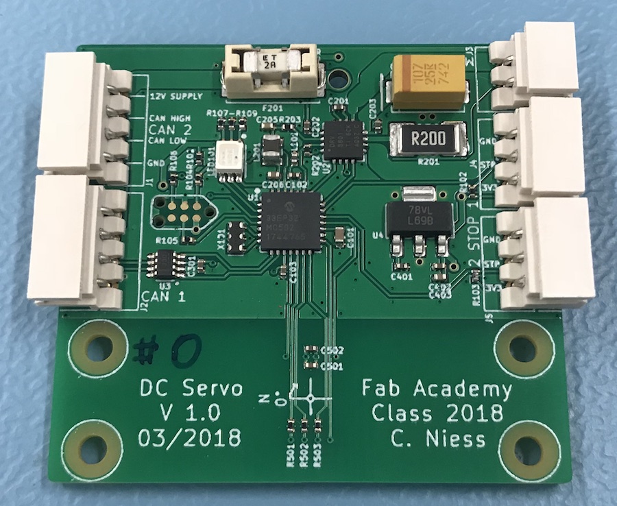
The idea behind the motorboard was to have a small, universally usable board to build DC-motor based servos to build a machine with distributed electronics. So, I needed some kind of data bus connection, a microcontroller, a H-Bridge and some kind of sensor to measure angular position and speed.

The Microcontroller
The microcontroller I used is a dsPIC33EP32MC502. I had planned on using a PIC because I'm used to working with them, so software development should be reasonably quick. I had used some from the same family in other projects (like the PCB for Output Devices), so using the version with a CAN interface from a family I already had lots of code snippets for promised to save more time.
The CAN Interface
I decided to use CAN bus in the placer for two reasons - One, I have wanted to play with it for quite some time, two, I might be able to integrate industrial modules into a machine built around it. What I did (and why) is on the Networking and Communications Assignment page.
The H-Bridge
While I could have built a H-Bridge to drive the motor from scratch, I really didn't want to, as it is more work than using a single chip solution. I have used the Texas Instruments DRV8801 for a few projects in the past, so I used it again for the motorboard - It's not exactly expensive, and while not very efficient, it can handle more current than the small gear motors I want to use. And it works with next to no additional components.
The Angle Sensor
The angle sensor is a TLE5012. I wrote a lot about it and how I use it in the Input Devices assignment.
The Rest
There is not that much else on the board - A voltage regulator, an PED and two inputs for endstops.
For a power supply on the board, I used a simple linear regulator, since the board really doesn't draw that much power (roughly 60mA at 3.3V). The one I originally chose (TPS7B6933Q) is a really rugged, automotive qualified chip that should survive (and filter) any transients on the potentially long cables in a small machine. When I got to ordering parts, it had become unavailable, so I went with a pin compatible, but less impressively certified one, an LM2937IMP.
The RGB LED I used is from a newish series of LEDs by Kingbright, made to use from 3.3V - Even the blue LED has a low enough forward voltage to do so (I don't know, nor really care, what magic they used to do that).
The endstop inputs are just that - Inputs brought out onto a jack to connect whatever switch or optical endstop I want. To be flexible, I put 3.3V as well as ground on the jacks, so most kinds of sensors should be simple to connect.
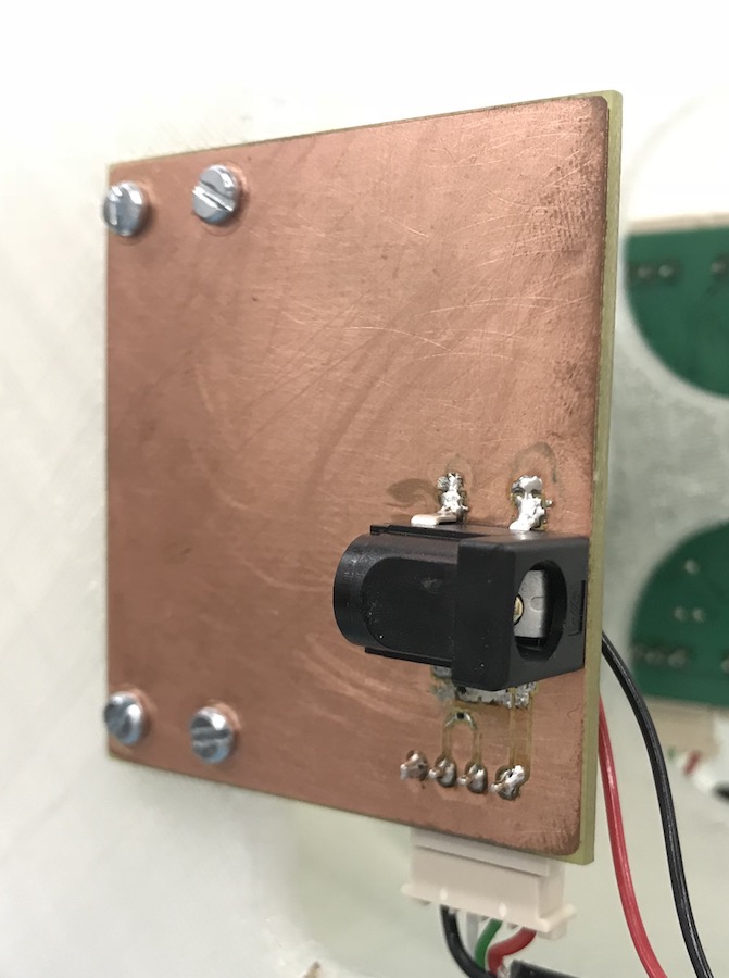
The Power Input Board
In the plans for building a placer, power would have been supplied to the machine through the brain, which has a round DC jack for connecting a power supply. As I didn't use the brain in the clock, that connection had to be done in some other way, and a somewhat tidy looking one at that. I decided to make a special PCB for that. With all mechanical parts of the clock basically the same, there was an empty spot for a motorboard on the mechanical mount of the minutes wheel, so I drew up a board of the exact size of a motor board, with mounting holes in the exact same places and a single CAN bus jack in the same position as on the motorboard. A DC jack went to what will be the back of the clock, on the "bottom" side of the PCB, and I put in a termination resistor for the CAN bus. The resulting schematic is more than simple:

I milled that board, soldered on the components and put it onto the clock:
final project -- about me -- weekly assignments -- fab academy
