final project -- about me -- weekly assignments -- fab academy
So Many Transistors...
An Updated Motorboard
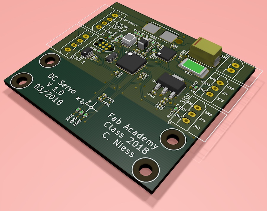
I changed a few bits and pieces about the motorboard while doing the layout, mostly due to little issues I ran into while working on a brain for the placer. First, I switched to different connectors - Smaller, cheaper connectors that should work just as well. I also wanted to have two CAN connectors, so I don't have to crimp two wires into one when wiring from one board to the next. Second, I found a type of RGB LED that is supposed to work from 3.3V-systems - Having blue LEDs on each board to show the machine is in automatic mode is cool, so I put one of those in instead of the three single LEDs. Third, I added a fuse in case the motor current runs out of bounds. That should, in theory, never happen, but that wouldn't be the first theory to shatter at first contact with reality. Differences to the schematic are minimal, but here it is again, with a link to the pdf version underneath:

The layout is finished by now, too. Since I will have silkscreen on those boards, I took the extra time to not only arrange component designators so they might help during stuffing the boards, I also tried to come up with (hopefully) helpful information for using the boards. Time will tell if it actually helps.
As a last minute change, I moved the magnetic encoder to the bottom side, so when mounted the top side (and status LED) will point away from the motor / spool, not at it.
I did not come up with 3D models for every component. That would be neat (and useful when planning how to mount the boards), but doing them is a lot of work. I want this parts library to be clean from a license-viewpoint, so I won't just drop in manufacturer-supplied models.
The project files are, of course, in my repository, and can be grabbed here.
We Have a Brain
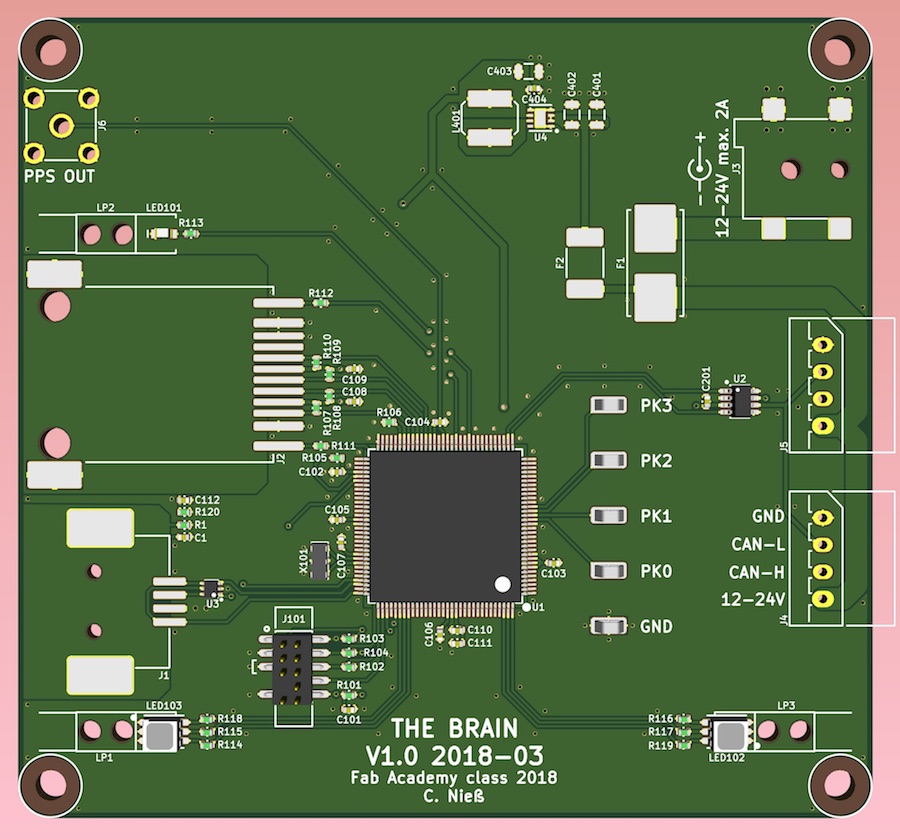
I also finished drawing up the brain:

That microcontroller is huge, and I'm using very little of what it could actually do, but it's a really neat to have ethernet completely on chip. It's not as flexible as the dsPIC, though, as most peripherals have exactly one or two pins they can be connected to - Just putting everything in the schematic so I won't have too many crossing tracks on the board won't work this time.
Still, with what little there is on the board the layout was pretty quick. I added a constraint myself, in that I want to use it for another project, too. It will have to fit into some kind of enclosure for that, and one that can be easily adopted to the multitude of connectors. I ended up choosing an extruded aluminium box that I used before. I will saw it off to be shorter, but that shouldn't be too much of an issue.
Again, since I will have silkscreen on the boards, I took the time to make it neat and (hopefully) helpful. I still have to draw the end plates for mounting it in an enclosure....
The brain kicad project is packed up for download here.
final project -- about me -- weekly assignments -- fab academy
