final project -- weekly assignments -- about me -- fab academy
Week 10: Magnets - They Work!
2018 Update: I never found time to look at what I started there again, and I need a different kind of input device for my final project, so I won't do it right now. I will leave this here, for anyone interested to look at. I mean, this thing could still be fun - There is working Human Interface Device code for those processors from TI, so it could be any kind of input device. Jump down to 2018 if you only want to see what I did now.
Week 10: Input Devices
As I have come to expect, this week was chaos. So, while I had started out doing the first hands-on work for my final project, none of its "input"-PCBs could be ready on time to do this week's assignment on it. I don't want to do a simple button (buttons are just boring until they bounce...), so I felt compelled to do something else.
Hardware
Daniel will need a bunch of distance sensors for his final project. The ones he will be using do look nice as they are small (compared to bulky ultrasonic sensors) and should be fairly directional - they are "looking" at a dot of light, not a diffuse reflection of a target somewhere roughly in front of them. So, I borrowed one to have a look myself.
I had made a bunch of USB test boards for I2C-Sensors a while ago, mainly to play around with stuff like the Invensense IMUs or the barometric sensors I stumbled upon.
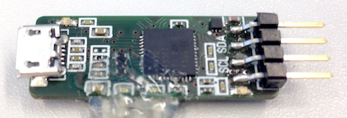
I had made them as a variant of another board, so they are rather limited in what they can do (two available pins are just barely enough to do anything), but for reading out a single I2C sensor they should just work. They are built around a Texas Instruments MSP430, a low-power microcontroller family I have done some work with for the lab. And while their documentation is horrible in some areas, the USB stack is well documented and just works. If you want to make your own, the design files (done in Target 3001!) are here.
For the proximity sensor, I fired up Kicad and made a tiny board to plug into the USB-thing:
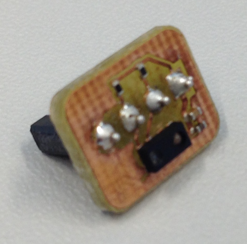
Again, it doesn't do much - it's just the bare minimum connection the VCNL4040 datasheet implies, not even connecting the interrupt pin (which I don't need, anyway). Not thinking straight, I also added the I2C pullup resistors to the board - there already is a pair on the USB board. It should work with them, though, and if not, I can still remove them. Again, if you want to build your own, do so: Sensor-Subboard Kicad Project
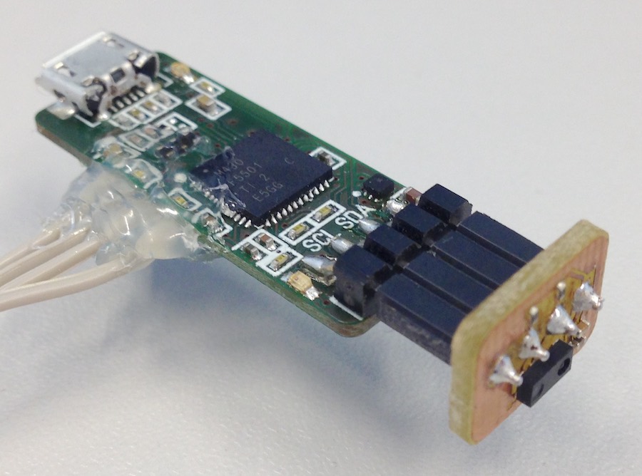
(The hot glue-stuff is the debug interface, by the way...)
Software
To play around with the sensor, I basically need three things:
- Software to do I2C
- Software to actually talk to the sensor (on top of the I2C stuff)
- Some kind of way to get at the sensor data I have read
General Software Stuff
The last part can, for the time being, be replaced by using the debugger and just reading from the microcontroller's memory. While not particularly convenient, this works fine for a first test. In the long run, I want to use USB for that, of course, so I will start out with one of TI's sample projects for USB - a virtual COM port that echos back any data you throw at it. That way, it will be easy to add in the USB output later, and until then it conveniently provides me with almost-done initialization routines for stuff like the somewhat complex clock system. I will, of course, have to change the I/O-initializations - I put in a way to switch off power to the sensor, which I now have to switch on, and I will have to configure the I2C pins to do their job. There are two LEDs, too, that I want to use at some point to show what the board is doing.
So, I need the following Changes to the default peripheral configuration:
- Configure P4.3 as a special function pin (SDA)
- Map SDA to use P4.3
- Configure P4.4 as a special function pin (SCL)
- Map SCL to use P4.4
- Configure PJ.2 as an output and set it to high (3.3V-Switch)
- Configure P1.0 as an output and set it to high (LED2, USB-side of the board)
- Configure P4.7 as an output and set it to high (LED1, I2C-side of the board)
To achieve those, I added some code to the imported TI initialization (in USBHAL_initPorts(void), hal.c):
// Configure port mapping controller
// interrupts have to be off at this point!
PMAPKEYID = 0x2D52; // unlock port mapping controller
PMAPCTL |= PMAPRECFG; // allow multiple unlocks
P4MAP1 = PM_NONE; // discard mapping of SDA to P4.1
P4MAP2 = PM_NONE; // discard mapping of SCL to P4.2
P4MAP3 = PM_UCB1SDA; // P4.3 -> USCI B SDA
P4MAP4 = PM_UCB1SCL; // P4.4 -> USCI B SCL
// for safety reasons we relock the port mapping controller:
PMAPKEYID = 0xFFFF; // wrong value locks the controller
// Reconfigure I/O-pins as needed
// The TI init already sets everything to output and low,
// so we don't have to set that
P4SEL |= BIT3 | BIT4; // set P4.3 and P4.4 to special function
P4OUT |= BIT7; // Turn LED1 off
P1OUT |= BIT0; // Turn LED2 off
General setup stuff is more or less done with that.
Sensor Reading Software
The sensor looks like a rather simple device, from a software point of view: It has 13 registers, each of them 16 bits long (and thus, for I2C, split into two bytes each). Into eight of them, you can write configuration to tell the sensor how to do its job. From others, you can read results. So, with I2C working, talking to the sensor shouldn't be hard - a few write tasks to configure it (if needed), and then a few read tasks to get results. The datasheet comes with a nice map of the registers:
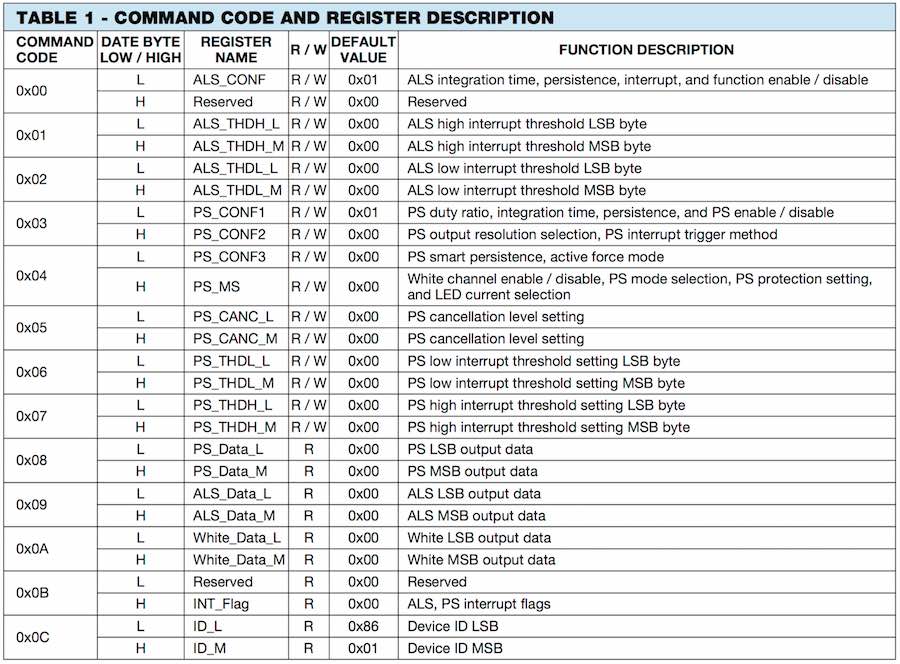
Given that I won't be using the interrupt feature for now, I can immediately discard Registers 1, 2, 6 and 7, leaving me with a maximum of four configuration registers to potentially write, with a lot of the short descriptions pointing at fairly obvious stuff - Switching the interrupt function on and off, setting the output resolution...
The first "command code" to look at is 0x00, doing configuration of the ambient light sensor. Since I don't want to use it, I can set the register to 0, disabling the ambient light sensor.
The second is 0x03, leading to registers PS_CONF1 and PS_CONF2.
Week 10: Input Devices
I restarted doing this assignment, since I need a specific input device for my final project anyway. So, from a rather imprecise distance measurement, I'm now switching over to a really precise angle position sensor.
Theory: Magnetic Angle Sensing
Magnetic position sensing comes in three general flavours, all of which have the distinct advantage of being contactless, in the form of working over an air gap - And it doesn't even need to be air. So, there is no friction, no wear and hardly any resistance to moving at all.
The first, and probably simplest way is to mount a generator to whatever you want to sense. It will produce electricity whenever stuff moves, and you will have a pretty good position estimate from the phase of the generated voltage - most often, it will be at least two voltages, or three. It's usually called a resolver, then, and they work fine - as long as stuff actually moves. As soon as it's standing still, you're on your own.
The second way of magnetic position sensing is equally known, and quite simple, too: Hall sensors will give you a signal based on the strength of a magnetic field along a specified axis. Pack a bunch of them into a case, either with their axis at an angle to each other or (for linear motion) offset, and you can estimate at what angle (or where) a magnet is with respect to the sensor. Those sensors have been around for quite some time, and have been used "forever" in smaller three-phase motors like the ones in computer hard drives.
The third way of magnetic position sensing is to use magnetoresistive sensors. Usable ones of those are a relatively new thing, as the effect used for them was discovered in 2007, and the first "simply buy it" chips have only been on the market for a short time. It allows for some interesting new ideas, like angle sensors that can measure over multiple whole turns, sensors that don't need power to sense (only to read the value from them) and others. It also allows for cheaper and more precise, simple angle sensors than the hall effect solutions on the market, which were quickly adopted by our friends from china for building camera gimbals for multicopters.
The sensor I'm using here is from exactly that application, it's used in a cheap camera gimbal that I watched quite a bunch of tinkering streams about.
Theory: Quadrature Interfaces
The sensor offers two interfaces, only one of which I plan to use. First, it offers a somewhat crippled SPI interface, which not only allows for reconfiguring, but also for reading absolute angle position data at high resolution. Having the highest resolution supported by the chip is an advantage, of course, and having absolute angle data might be another advantage in some situations. The SPI interface takes a serious amount of time to use, though, so that great data is only available with some delay. Since I mostly want to regulate the speed of my motors, a realtime interface with no delay would be a lot better. The chip offers one, in the form of a quadrature encoded signal. It outputs two square waves, at a (theoretical) 90° phase angle, with their frequency depending on the speed of rotation, so you can get speed, direction and incremental position information from it.
There are a few different approaches to reading that data. The most simplistic approach is to poll the signals, and interpret any changes you see. That is a lot of work, imprecise and only works for slow speeds (think of the encoders used for human input), but it works. A little easier is to wait for changes on those lines, and react to them in one or two interrupts - it gets easier when you don't need the full resolution of your encoder, as one interrupt will be enough. The nicest approach, though, is to have specialized hardware that "just reads" the signals and can tell you, at any time, where the encoder is at. With the motorboards, I specifically chose a microcontroller to have such an interface, and as I haven't used it before, it will be interesting.
Practice: Reading Quadrature Interfaces
The Quadrature Encoder Interface (QEI) is complex enough to warrant its own datasheet: DS70601. Using it is no that incredibly complex, though (at least not compared to modules like the CAN interface), as there is actually little configuration to be done - There are only three configuration registers, one of which is almost completely status information (see pages 15-6 to 15-11 of the datasheet - That's way too much to copy in here).
Still, the first step of using the QEI is, of course, to configure it. The first part of that, during startup, is to assign pins to the inputs of the QEI module:
RPINR14bits.QEB1R = 42; // assign pin RB10 / RP42 to QEI B
RPINR15bits.IDX1R = 41; // assign pin RB9 / RP41 to INDEX
RPINR15bits.HOM1R = 44; // assign pin RB12 / RP44 to HOME (that's endstop 1)
In the initialisation function for the QEI, called later in the startup process, the necessary module configuration has to be set. Two basic kinds of operating modes have to be selected in the QEI Control Register: First, there is Counter Control Mode, defining what kind of hardware we're using the QEI with. Since quadrature encoder mode is the default, there is nothing to be done with that. Second, there is Position Counter Initialization Mode, defining how home and index affect operations of the module. There are two interesting modes for us, 000, with the index pulses being counted, but having no other effect, and 011, which does a precise homing from the (imprecise) end stop and the (precise, but repeating) index signal. Since we won't start up in homing mode, we set to 000, which is again the default.
From all the fine-grained configuration in the I/O Control Register, I'm only using one right now - Inverting the home signal, as it is active low in hardware. The index signal is active high from the sensor chip (we checked that during the group assignment), and I don't care for phase errors due to possibly inverted A/B inputs. I also don't use the filtering option right now, as the signals looked free of the kinds of short spikes that it's there to filter. So, there is only one bit to set:
I could configure interrupts now, but I don't need them, so I can leave the QEI Status Register alone. What is left to do is to switch the module on:
The program can now, at any time (for example, during a timer interrupt) read out the absolute axis position (32 bits in Registers POS1CNTL and POS1HLD, must be read in that order), index pulse counter and speed (as in, counts since the speed register was last read). With a bit more configuration, it is also possible to read the duration of the ongoing pulse, which is good for measuring very, very low speeds.
Testing
An input like that is actually not that nice to test. For a very first, initial test I just crammed the initialisation into the code, held a magnet in front of the sensor and stopped the PIC with the debugger. Reading the QEI registers that way, the values looked somewhat sensible, but that's about it. Then, I did a better test during Interfarce and Application Programming:
It works.
And you can, of course, download the software.
Another Board
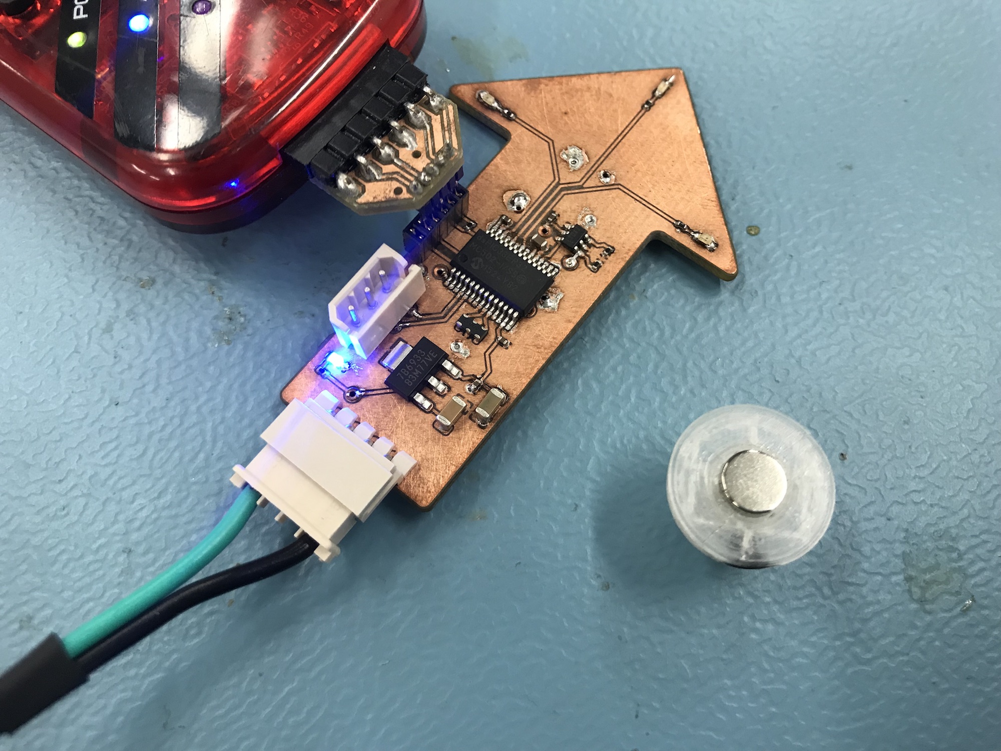
Since someone had the idea that I have to make a milled board for this assignment, I milled a board. First, of course, was designing a board (so it can be sensibly milled). I worked on the basis of the motorboard (so I can keep the software), but switched to cases that are a lot less work to solder on milled boards. So, the PIC on there is basically the same dsPIC as on the motorboards (just in a different case), the sensor at the bottom is the same one as on the motorboards, and basically everything around it is the same, and connected the same. I did add a new IC, though: Since there are problems with the magnetic sensors and their ultra-short index pulses in combination with the PIC's quadrature interface, I put in a pulse generator that will output a roughly 10µs pulse to the PIC when triggered by the original index pulse, in the hope of getting better output.

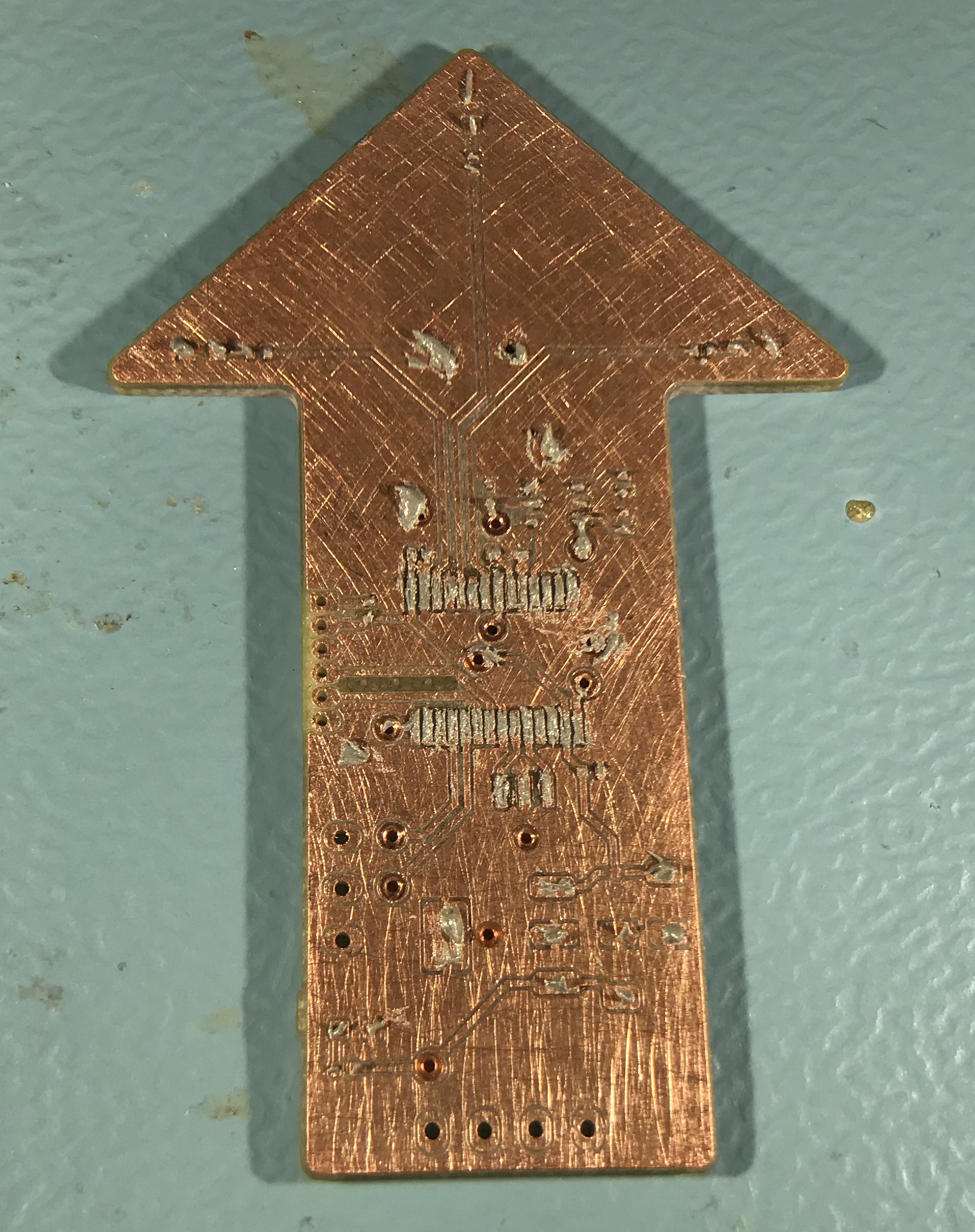
I wanted to do a shape less boring than the usual rectangle with this board, so it became an arrow. It doesn't really serve any purpose, as it can't move to point at something sensible, but it looks cool...
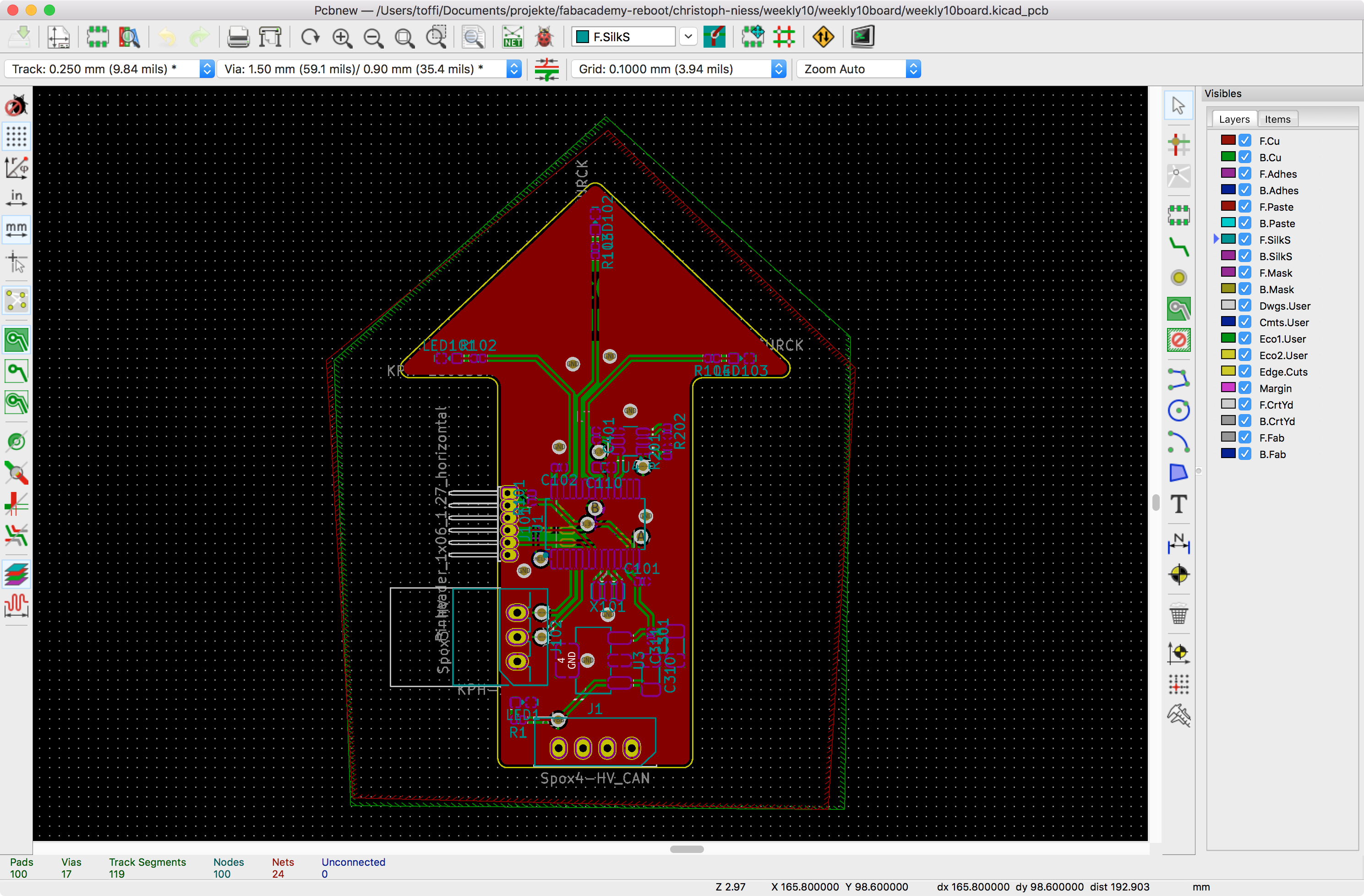
Then, I milled it on the LPKF:
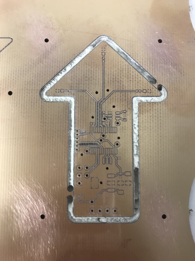
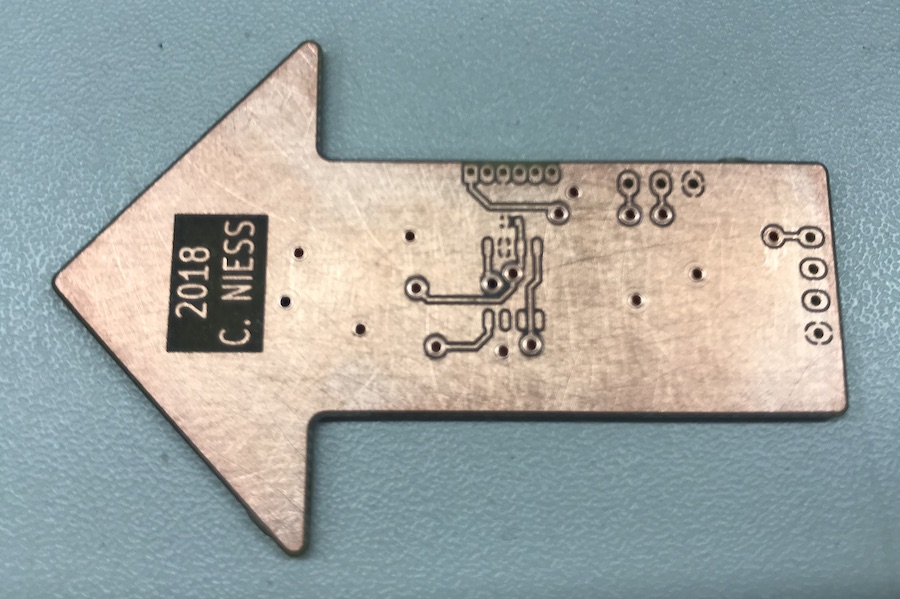
After sanding down the board and putting in rivets for the vias, it looks OK:
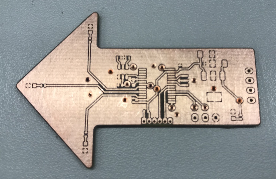
I had to work double sided to get some stuff sensibly connected, so it's a rivet or two...
The source files for this board are available, of course.
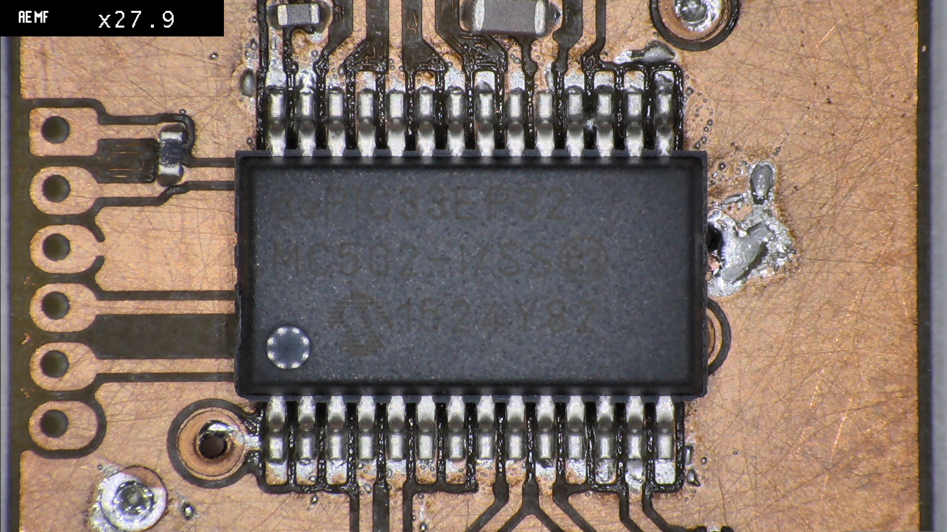
I applied solder paste to the pads of the PIC using a technique I hadn't really tried before: I smeared a thin layer of paste over each row, covering everything. Then I used the tip of a scalpel and scratched the paste back off between the pads (with the milled boards, the milling tracks can guide the tip of the blade by feel, so it's not that hard). The result doesn't look bad:
Then, I placed the components. I only did the upper side components, as glueing on and placing the two components on the bottom would have been quite the effort for something that can easily be soldered by hand afterwards. The board is now ready for the oven:
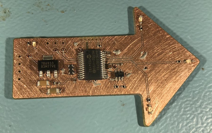
I soldered this board in the drying oven, at 265°C, for a bit more than 2 minutes (watching it and taking it out after all tin had melted and stopped bubbling from the flux). Boards that small really don't take long. The result of the experimental solder paste application looks more than OK:
I then soldered on the jacks and the components at the bottom - It's just the magnetic sensor and one capacitor. Looking back, it would have been more sensible to have the sensor at the top for this board... Not for soldering, but for actually using it.
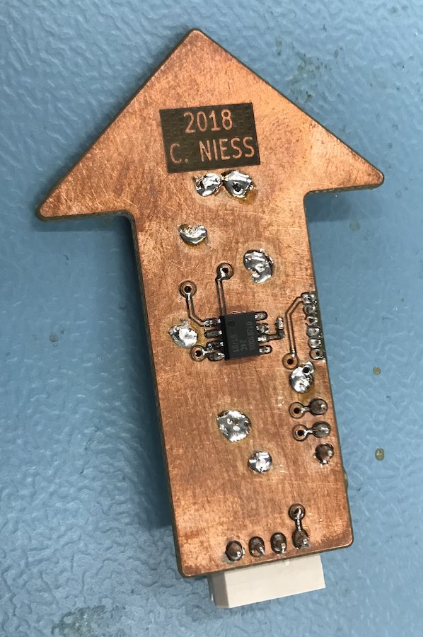
Then, I put in some software. For now, it runs the same software I used to test the encoder interface on the motorboard - everything is wired the same, so it runs fine, and I can read out the encoder counts with the debugger.
final project -- weekly assignments -- about me -- fab academy
