In areas of abundant day-time sunlight, as luckily we tend to enjoy most of the year round here in Barcelona, it seems amazing how we can't make more use from the sun's energy on a personal level. Solar energy provides a clean and renewable source of power that can be a good alternative to combat our collective dependency on fossil fuels. As the price of investment and the cost of solar panel production goes down, due to increased market interest, and advances in manufacturing techniques and technologies. It is a excellent area to focus our design attention and innovation. Refining and developing core system components and potential outcomes, and making these systems more implementable, cost effective, ecological and easier to create, and maximising the efficiency as far as possible. If we could create a relatively light weight, collapsable, semi-transportable and relatively cheap solar energy solution. We might see more people turning to the sun as a reliable form of back up power, and energy. Utilising A solar tracking system increases the efficiency of a solar panel by enabling more of the suns direct energy to be absorbed and converted into usable electricity in a given daily cycle.
The big drawback however, is that nearly all tracker systems rely on using some power to move the structure and effect the motion needed to track the sunlight. (with the exception of compressed gas or pressurized liquid, - heat transfer, exchanger displacement systems). Therefore any power spent on moving actuators and mechanisms in our design needs to be kept to an absolute minimum wherever possible.
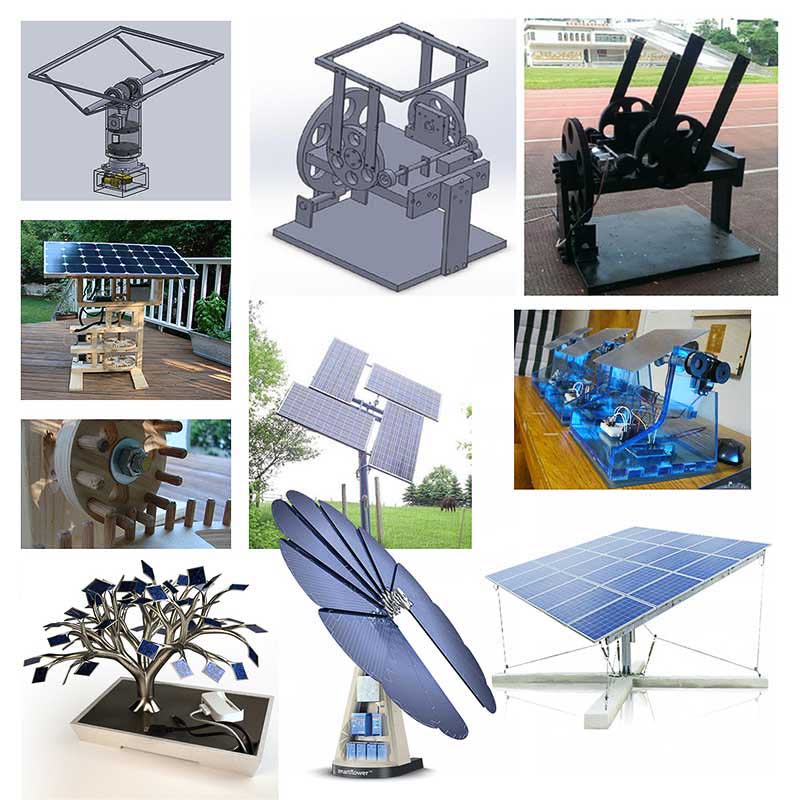 Existing Designs
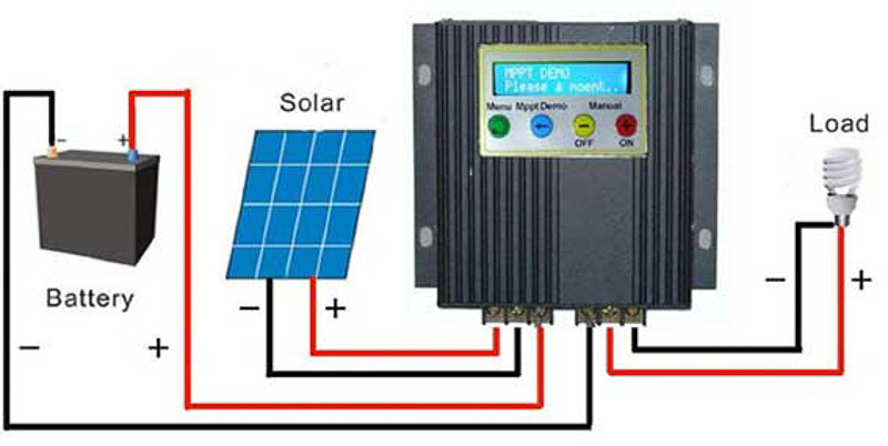 Solar Generator Diagram
Solar power generating systems will incorporate the following key elements:
1) The Collector - most commonly P.V. or photovoltaic panels. Which absorb the suns light energy and convert it into useable electricity. Other variations include using the energy to heat water or other liquid mediums such as in vacuum tube arrays for central heating or hot water supply in homes. A Photocell basically works by having electrons travel from an anode to a cathode through a P-type and an N-type junction. The N - negative layer is doped to have an excess of electrons, whereas the P - postively charged layer will have a deficiency of electrons. When a p-n junction is formed, some of the free electrons in the n-region will diffuse accross the junction to combine with the holes in the p-region to form negative ions and resulting electricity. At the junction between the layers is a depletion region where postive ions are left behind at the donor impurity sites. For more information you can see a link here:
P-N Layers in photo cells and diodes.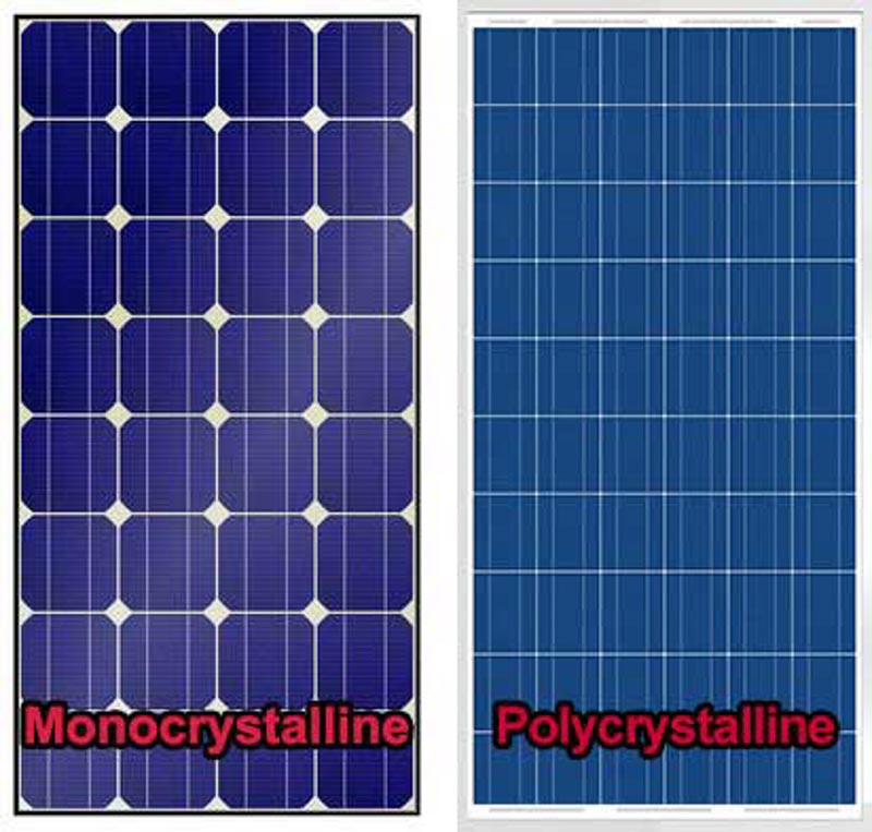 mono-crystal vs poly-crystal p.v panels.
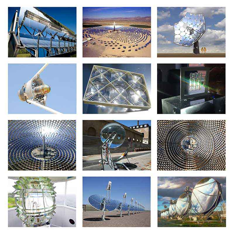
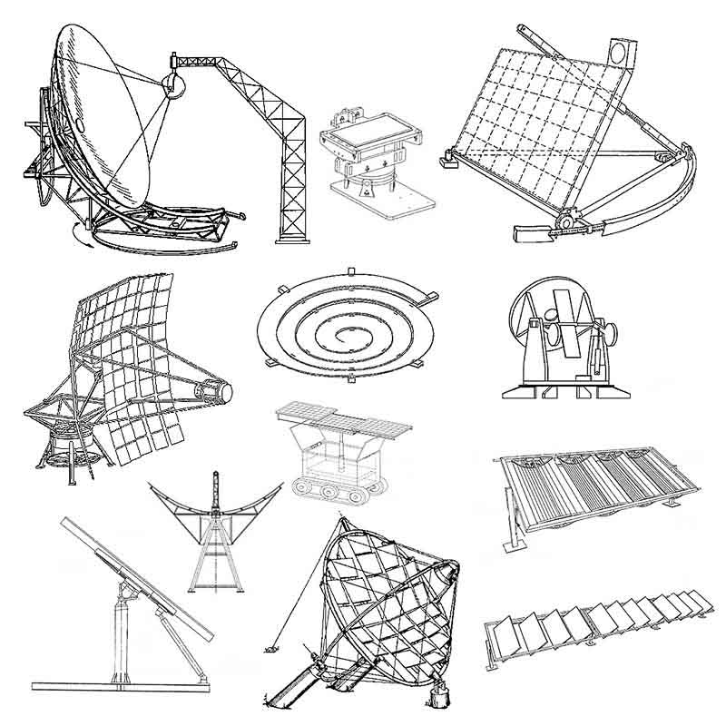
On a more exotic level we have concetrated voltaics where the sun's light is reflected and focused with mirrors or lenses increasing it's intensity at the point of collection. Different collectors appear in the form of flat panels, parabolic dishes and troughs, or helios arrays.
2) The Battery or Power Bank - used to store electricity that is produced, not allways neccesary in larger grid-tied systems, or indeed for very small current aplications. However, if you intend on generating excess energy and want to store it for using the system at night, or on darker rainier days when the panels will not generate power, a battery bank is essential. The system will be undergoing regular daily charge and discharge cycles so you must ensure suitable batteries are used. These are commonly known as deep-cycle cells, neccessary to maximise the life and efficiency for this application. There are four common types of cell now readily available:
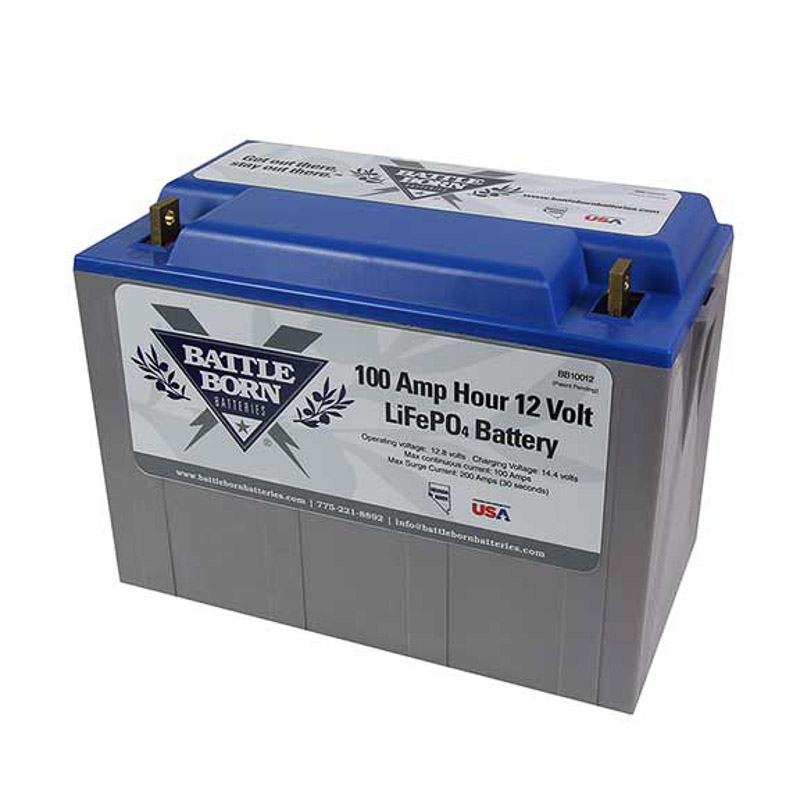 Deep-Cycle-LiPo
Unfortunately the best of these battery types using the latest technologies such as lithium variants can come at a significant cost. All have a limited useable lifespan, and unfortunately are inherrently difficult to dispose of or recycle. The size of the power bank you choose should be proportional to the output from your panels or collector.
3) The Charge controller is needed to regulate and control current and voltage input to the cells as they charge, these generally come in two types 'PWM' - pulse width modulation, or 'MPPT' - multi point power tracking charge control. 'Mppt' being the more sophisticated and efficient for this application.
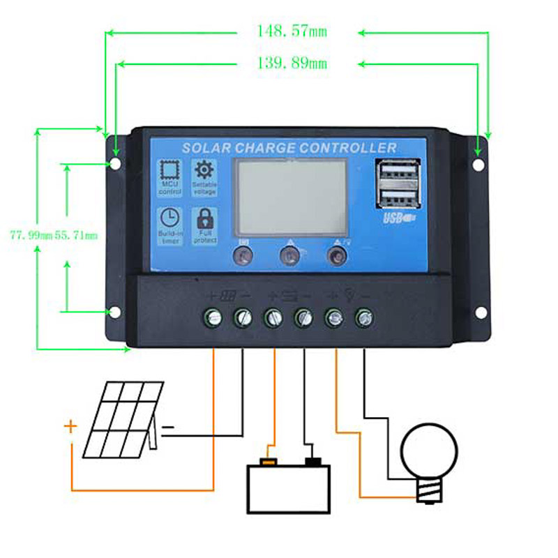 pwm controller
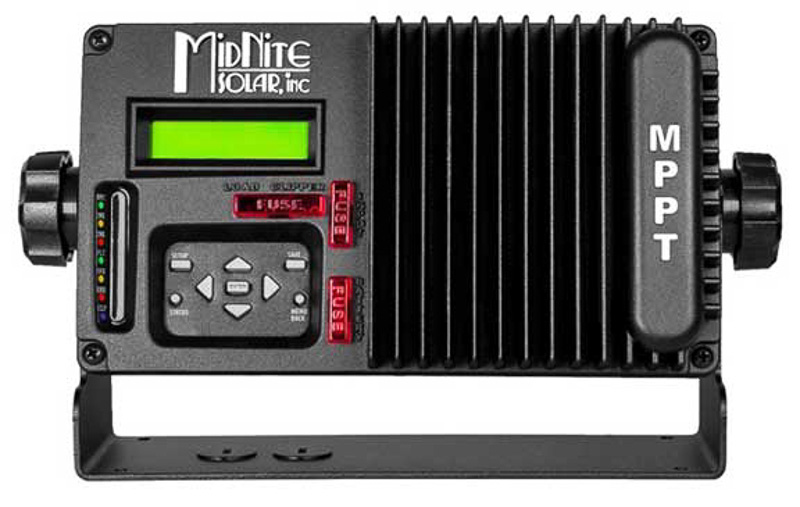 mppt controller
4) The Inverter and distributor in order to regulate the output from the battery bank and relay the power to a home-breaker and outlet to power your appliances, or back to the main grid.
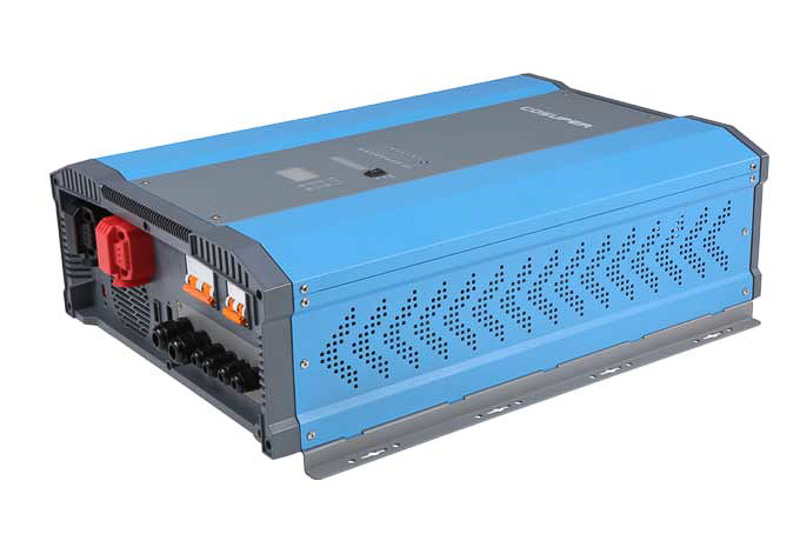 inverter
Important things to consider when planning a solar energy system...
Output:
What do I intend to power and what is my expected daily usage? - measured in Watt hours.
Input:
How much sun is there in my area? - Solar Panel area size and power calculations.
Storage:
Battery bank capacity - specification and sizing. Taking into account dis-charge values of your cells. It is a good idea to make the calculations based on an average use to give a rough idea, but you should also try and factor in peak and surge values for the appliances you intend to use at different times of the daily cycle. For example if the batteries need to be maintained at half there charge to maximise lifespan, you will need to double your size requirements.
As we know, the suns movement is roughly the same each day, in that it rises somewhere over the East hemisphere and sets somehwere over the West. It is at it's highest around mid-day. This daily motion or angular direction the sun's angle in the sky from an observed point of interest or origin is known as the Azimuth.
For the majoirty of us that are living in the mid northern hemisphere we are generally observe the high noon sun in the southern hemisphere of the sky. However as the seasons change throughout the year so too does the suns observed path, position and angle within the sky. This is known as the suns altitude or elevation above the horizon. Between the Equinoxes; 20-22 of March and September; and the Solstices; 20-22 of June and December, the position of the suns angle in the sky changes by approximately 23.5°.
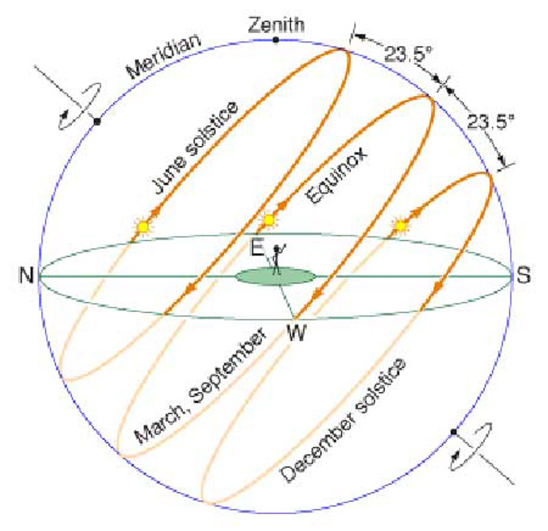
In order to maximise our collection of solar energy the surface of the reciever and it's angle of incidence ideally needs to remain aligned perpedicular - 90° to the direction of the sun as it moves across the sky. Here on earth the sun's energy is hitting us most directly at mid-day, when it feels the hottest, when the angle of incidence becomes greater as the sun goes down toward the horizon the intensity of light decreases and we feel it getting cooler.
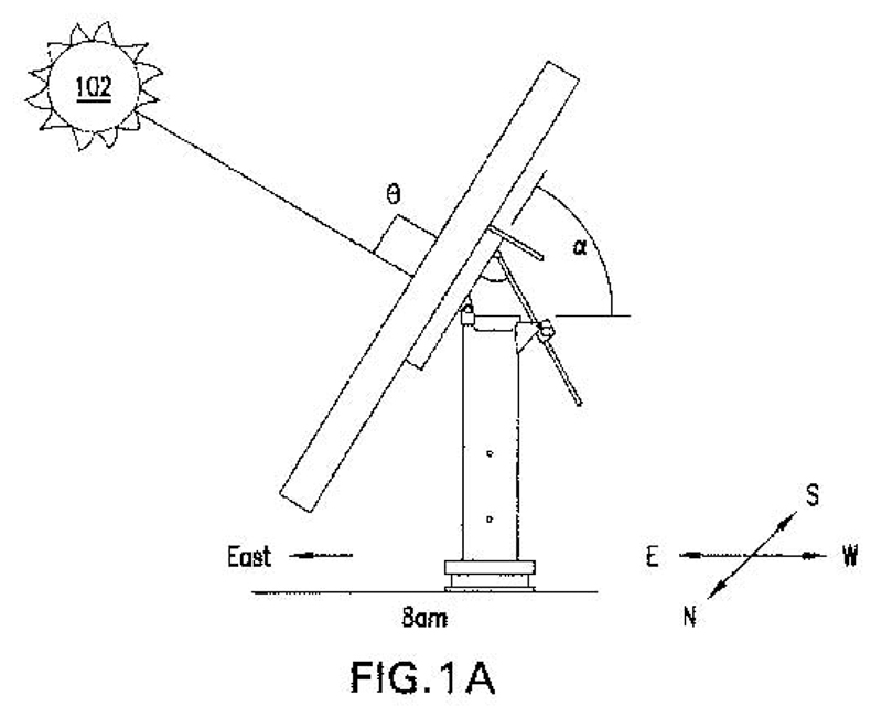
Setting up solar panels in a manner so they most effectively facing the sun for the maximum ammount during the day requires planning and knowledge of your global position in order to establish the best placement and angle for the panels. A single motion tracker with daily azimuth tracking can greatly enhance the efficiency over a fixed flat mounted panel, particularly during the morning and evening hours. Whereas a dual axis system will also track the altitude angle providing further accuracy and efficiency throughout the year.
Tracking the position of the sun from your origin can actually be achieved mathematically very effectively and accurately by using your global position with coordinates of longitude and latitude for any given time. This can be done using a GIS - or geographical information system, along with some very refined mathematical algorithms used for calculating the solar zenith and azimuth angles, which are based on astronomical data and irradiance of the sun and the suns incidince to the earth. There are several good solar calculator web-sites to do the math for you and find the suns exact path and position related to your global viewpoint. There have been many good published articles describing solar position algorithms for solar radiation applications such as this. However, The algorithm currently known to have the highest accuracy is the Solar Position Algorithm (SPA) - by the National Renewable Energy Laboratory (NREL) of the US. This is a step by step procedure for implementing an algorithm to calculate the solar zenith and azimuth angles in the period from the year -2000 to 6000, with uncertainties of ±0.0003/.
Solar Tracking Astronomical Algorithm for solar radiation applicationsTracking the suns light either across a single daily axis or with a dual axis movement can greatly increase the ammount of daily electrcity produced by a solar panel. Various statistical evidence suggests and proves that by adding a tracking system to a solar array can easily gain you more than 30% energy when compared with a fixed orientation reciever. For more information on Suns movement, celetial spheres and ecliptics please see some of the links above.
Please also review my intitial progress and our first tracker prototype we designed built and tested for the group project during Mechanical, and Machine Design weeks:
Mechanical DesignAlso here is a link to my primary planning scheme for my final project.
initial project planning - google-driveMy aim for this project is to build a durable and functional scale model that will move in both axis to track the direction of sunlight. It should position itself automatically at an angle of 90° (with +/- 1° accuracy) perpendicualr to the angle of incidence from the sun.
A light sensing Module mounted to the face of the panel, that will consist of four phototransistors will send signals to a central programmed micro-control board. This in turn will be conected to a dual H-bridge motor driver break-out board, which outputs to two 12V D.C. motors. (These could be powered by an an external battery source or the theoretical main solar battery bank).
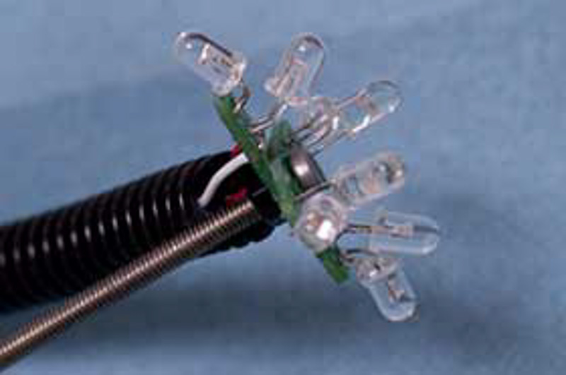
After testing and research it was decided that D.C. Motors would be a better option over stepper motors, because of their higher torque to power ratio, when appropriate gearing is used for slower speeds. They don't miss steps, and have no continuous current draw in a '0' state. Ultimately a motor with feedback control, or separate positional encoding would be ideal for a closed loop application such as this system. However, it is not absolutely essential as these can be quite complex or expensive units. We will program the output to our motors depending on the different weighted values taken from the analog light sensors, to bi-directionally position each motor and coiincidentally effect the motion of each axis of the frame. With the goal of each motor to reach a balanced, centred aligned angle facing the light-source. Here is an example of one such light-sensor design using clustered LED's.
I will require a minimum of 4 analogue inputs for capturing the data from the light sensor module with it's four photo transistors. And also 4 digital outputs for driving each motor. Additional limit switches at the mechanical extents of each axis of motion would be a benefit. And potential added features for manual override control, or network signal processing, to build an interface or application for these montioring and control functions could would also be very nice and a possible extension for a future itteration*.
Please see interface and application programming weekUltimately, all this means that a smaller Tiny 44-45 processors will not have sufficient I/O pin connections, even the At-Tiny 84-85's would have limited capabilities. I have therefore chosen to base my design around the ATMega 168, or even a 328p micro-controller. I will be creating an Arduino replacement board to control my input and output devices. I have deliberated and compared a few itterations of arduino style boards from previous fab students and studied the possibilities. These 'fabable' boards are fully compatible and can be programmed using the Arduino IDE and libraries, and can be created from standard components found in the fab inventories. I will use these board layouts to reference from and as a basis for my design. The main contending choices include:
Fabio1.1I read through documentation for each of these boards, and spoke with some colleagues and instructors about the differences and asked their recommendations. By the time I was ready to mill I had the choice of both the Satshakit and the Barduino boards ready to output from prepared Eagle files.
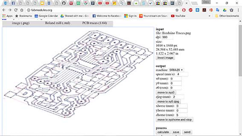
I did encounter problems with some of the trace sizes and routings especially around the microprocessor. In that they are very narrow and difficult to route cleanly using the 1/64" mill bit. You will probably have to select a smaller trace width, something like 12-14. Even so, Eagle identified a huge number of clearance issues, and wouldn't pass the DRC check, there were too many to modify in the time I had, I knew the traces were correct and from previous confirmations by instructors that it was indeed fabable. So I began editting all the noted problem areas in the .png image file directly, I then checked the tooling and cutting paths using fab-modules until there were no touching traces. I also even made a vector path image of the same file to try and output that through fabmodules as a drawing file, but I haven't yet found the time to test if this option is possible.
I had already gathered the components for the Barduino version and was keen to move forward making this more compact board. A benefit was that it included the standard fab ISP connector for programming, and the FTDI header for power and communication thereafter via usb adapter.
I was thinking I may have to try using the precision 0.01mm end-mill to manage the detail around the processor area, but we only had one of these left in our lab, time to cut was also a key factor so this was best avoided. After further editting of the Png. image and the settings within fabmodules I finally managed to get all my tool paths to cut successfully with the 1/64 bit. I found by slightly increasing the offset or overlap of each path and reduing the tool diameter a fraction from 0.4 to 0.38mm, it would define more of the smaller detail.
I have urgent need of a control circuit board such as this for testing and progression for my main project build. However, as a futher itteration of my control board I will really need to modify the original Barduino sketch and layout more than I have here, in order to make it my own version and design. I will try to open up more of the un-used analogue pins, and delete any unnecessary components. I may even think about combining the motor driver circuit onto the same board too, but for now I will push-on with making this board to give me something to test with and try to finalise my project in time. eek!
 successful traces
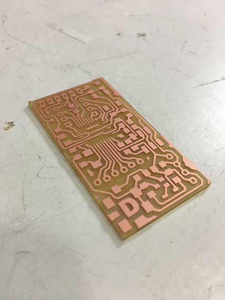 milled barduino board
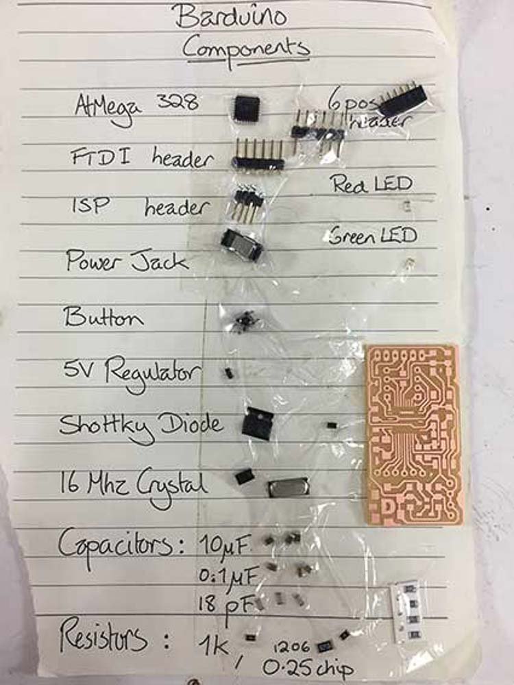 barduino components
Luckily for me my mini Barduino traces cut correctly, I then cut the holes to mount some connection headers through the board, and finally the border cut giving me my blank circuit board to be stuffed with components.
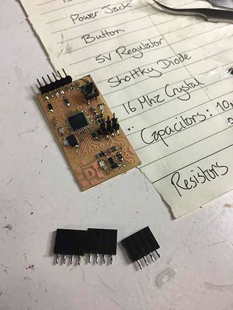 Barduino soldered
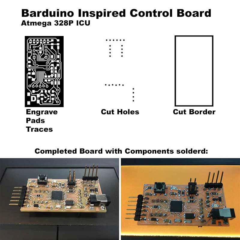 Barduino control board
The list of components for the board is as follows:
BOM*
I was able to get all the components soldered correctly although I must admit the small size of the board made this a little tricky. After completing what looked like a pretty good effort and testing for continuity and connections. I then plugged the board into my computer for a smoke test, happy to see the red led light up. Then to be sadenned to see that it returned error messages when trying to burn the bootloader! it would not upload a simple blink sketch as a test in Arduino...
 Flash Programming - Burning the Bootloader - fail!
The next day back to the multimeter to check through my connections...
There were two suspect diodes that were potentially wired the wrong way round for their polarity and so I replaced these along with one of the LED's and a couple of suspect resistors... but still I had no joy!! So I tried to bootload on some other peoples computers and using different programmers, but was still getting the same error codes. Either it would be the serial Port access to my board restricted for some reason, or I recieved a message about AVR Dude and STK500 with sync errors. after multiple sends
First I tried re-installing the AVR dude drivers, (I needed to disable driver signature verification in Windows 10 for this to work,)
Additionally, there are a few versions of the 328 chips with the 'P' 'AU' etcetera, I checked and ammended the signature codes within the AVR config file. Ensuring the correct code was saved for the 328P chip I was using. Here is a useful cheat sheet for finding correct signatures of each chip:
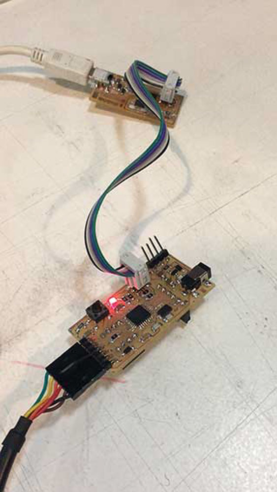
Eventually after much diagnostics and puzzlement and a lot of help in the end from instructors Xavi and Santi, I was able to burn the bootloade by using an older version of the Arduino IDE - 1.12 on my instructor's mac, as 1.8.2 had not worked. I was very happy to get the blinking light and see my board now working.
Light but no life! And finally burning bootloader successfully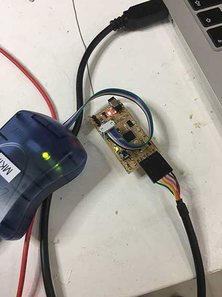 Burning the Bootloader - Green light!
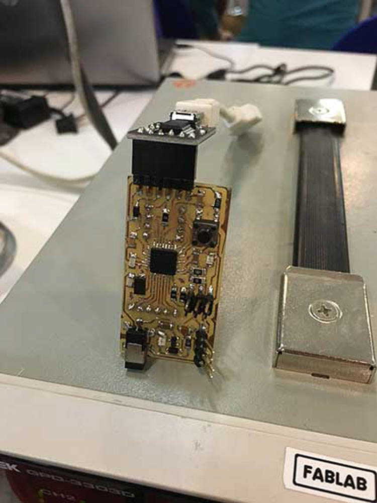 Barduino - glory shot
Now for a quick set up with servo motors to test motion control, then on to the development of my sensor module board and dual motor driver carrier boards for my project.
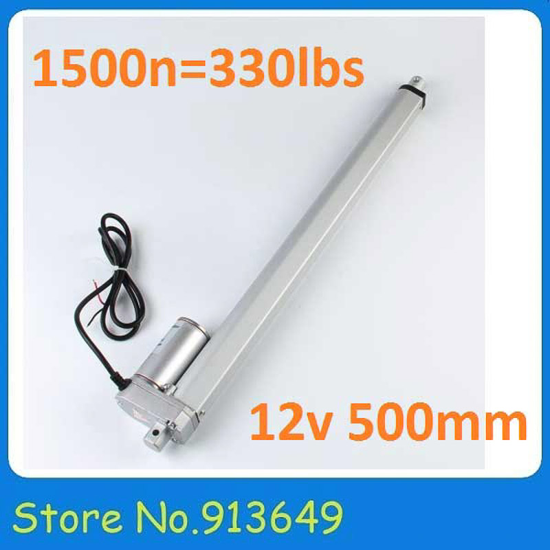
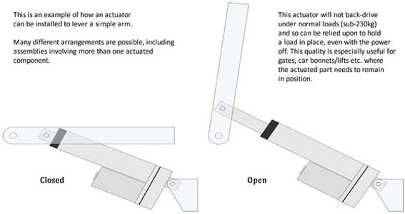
I am now in the process of making the sensor module board, and motor driver board components. And also focusing on constructing a well built frame to fit my motors. I have now sourced a pair of DC. linear actuators at a reasonable price, so I will be using these to drive each axis of the tracker in a pan and tilting motion. Having a rotary geared pedestal base, or a worm, or planetary gear arrangement that I had been working toward trying to achieve, was now just to complicated for me to fully resolve in the time available to me, I was not happy with the integity of my 3D models or the results I would get with the 3d printer for these load bearing mechanical parts. These linear actuators have sufficient gearing built into them to provide steady controlled low speed with high torque for our application, they are properly sealed from the environment and easily moutable via pivot fixtures and mount plates at either end.
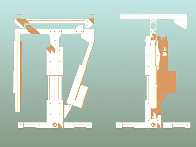
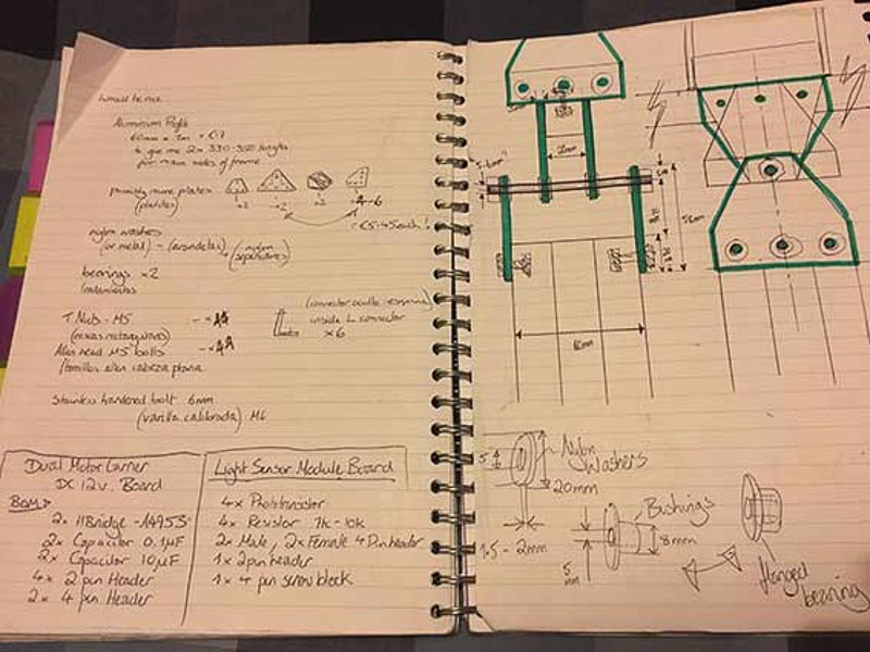
My current task is also to focus on a lightweight and strong aluminium frame; with potential 3d printed end caps and joint fixtures, I am considering using shaped metal T and L brackets or plates for my joints. The frame design itself will encorporate three main sections: The 'base and central coloumn', connected via pivoting hinge to the top 'L frame' frame part - providing vertical tilt motion. An upper 'top frame' section, provides mounting area for a solar panel and the horizontal pan movement. I will also need to think about designing a secure protective housing for my electronics; Sensor module, Control and motor boards and the wiring.
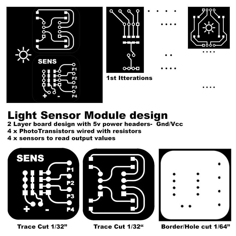
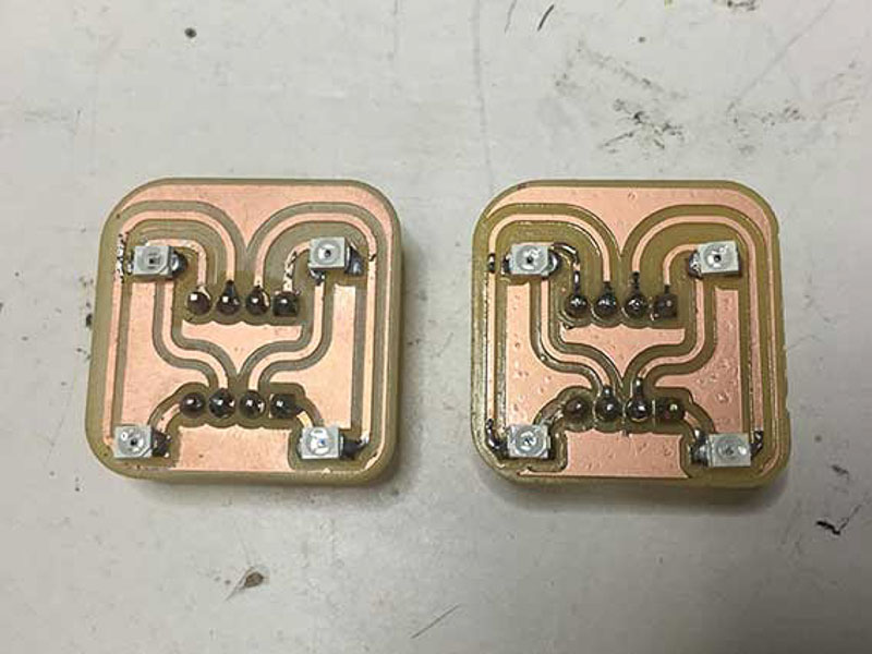
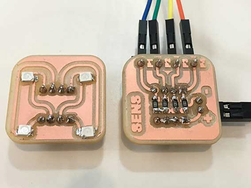
Having now spent a long time looking at existing designs and the different light sensors available, and undergoing various testing and breadboarding using LDR's which can be seen at the end of Input Device week. I am moving forward with a design to the darlington phototransistors. I will make my own break-out sensor module with these sensors positioned top-right, top-left, bottom-right and bottom-left, integrating resistors and wiring block and neccessary cabling to output the analogue light values to my control board.
I came up with these designs in eagle; a mini stackable, ported light sensor top shield, connects at the rear to the resistors and signal out wiring block with Vcc and Ground connectors. The aim with this is to then have a pluggable device that fits to the frame that will be aligned just above the flat surface of the panel.
As I had already built a driver board for the stepper motors, albeit with limited success. I now needed to produce a dual D.C. motor driver board. I am aiming to drive two 12V D.C. Actuators rated at 2A. They work with an internal rack and pinion driven by a motor to drive the linear piston in and out. I intend to use 12V Actuators for the design as they provide a fully sealed housed motor unit to protect them from the elements. They have fixtures at each end for mounting, and crucially the internal metal gears have the neccessary reduction in speed, and a high torque output that this kind of application requires.
After some testing and extensive research into gearing ratios, and other drive train configurations the complexity of mechanics became too time consuming and increasingly difficult to fabricate in the time I now have available. These Linear style Actuators are availabe in a range of lengths and sizes and types; crucially the stroke length refers to the extension from body. However, the total length, at each fixing pivot point or end to end, when fully retracted and fully extended must also be taken into acount for the frame design. I have had some difficulties deciding about the placement and exact mechanism for the pivoting hinge points in my design, in order to most effectively mount these actuators to a frame to give me the desired range of movement.
I also needed to create a dual DC motor carrier board to be driven by my main b'arduino control board. I began to re-design a circuit for these purposes in Eagle, resourcing and referencing the files from Niels examples and pulling in components the fab-library to make my own completely fresh design, essentially using two 3894 motor drivers. After many frustrations in Eagle to get this right, I was stopped and greatly aided by a fellow colleague, as he already had a similar working board. So I give credit to Nisar Ahmed Siddiqui for showing me an image of his circuit layout to reference, thanks Nassar, it was an enormous help. And enabled me to create the files to make my own motor board. These are the results...
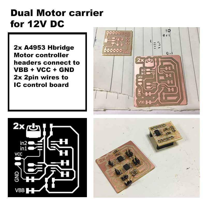
At first despite having made a lovely board it was fraught with issues, and it seemed to be getting a 12V reading using the voltmeter for both the Ground and VBB connections! very troublesome! Somewhere there must be a loose or bridged connection. After changing components frantically and checking all my solder joints I was still at a big loss, and so I finally resorted to remaking the board, but re-using most of the components.
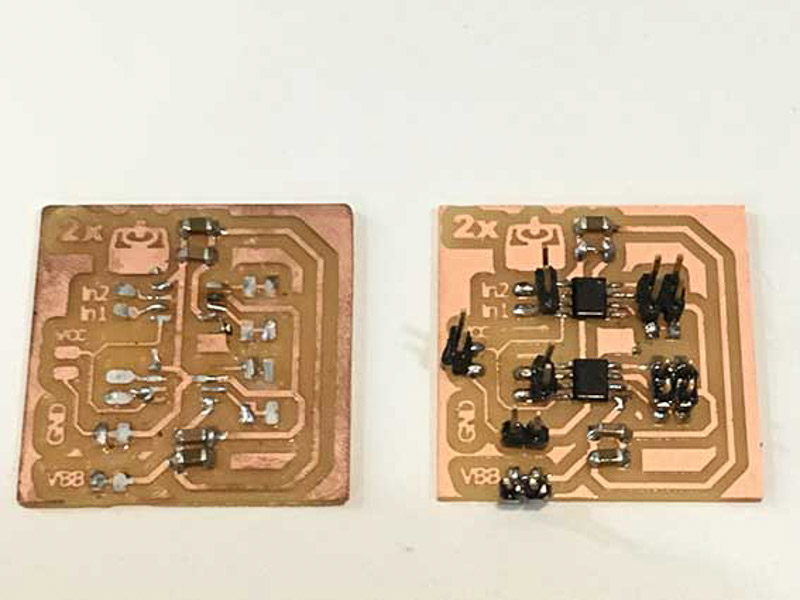
After some further testing I eventually managed to get the second motor board I built to work and enable some testing of my code to move the motors.
Motor Board DC Actuator testI have chosen to base my frame largely in aluminium, it is both lightweight and very strong and resilient, stiff but not brittle and fairly easy to cut and machine. The profiled extrusion sections are very apealing, often refered to as '8020', 'T-slot' or 'V-slot' this material is popular for machine building amongst the maker scene. The stock section aluminium material can be easily modified or adapted as necessary, and being a modular system the fittings and joints should be easy to assemble and disassemble and configure as neccessary for prototyping purposes. It will also benefit from being weather and corrosion proof if outside in the elements, very suitable for use in a final tracker design.
One of the main issues I have been having is with the hinged joints, or trying trying to think if I could 3D print a functioning part with more durable internal bushings or inserts to strengthen the mechanical joint. Here are some of my 3d models as a working progress for my final propsed design:
To some extent there were restrictions during the design process, due to what I could or couldn't source, what I could fabricate and what would be viable in the limited time I now have available. Having chosen this system I found it quite difficult to obtain and specify the exact parts and screws and fittings that I needed, and parts to experiment with were not cheap!
After several hot sweaty jaunts running around barcelona to buying aluminium profile sections, T-nuts, metal plates, or allen hex bolts in specific length and diameter. Or to enquire about bike sprockets, gearing or nylon spec. Editing some features here or there and trying to finalise things about the design. These were the initial parts I cut to try and fabricate hinges from, but unfrotunately in the scale I was going for, they proved really too small and the metal was too soft to accurately shape and make solid working hinges parts from.
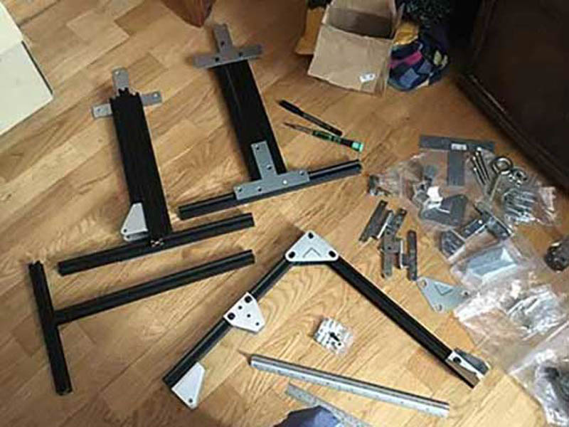
These are the other structural parts I have gathered so far to begin to fabricate the frame for this project.
I have designed some potential plastic parts - slot-fit fixtures for the top and base of my aluminium frame, providing feet, support, and the base hinge fixture point. Here are the results of a 3D test print I made to test the concept for this part.
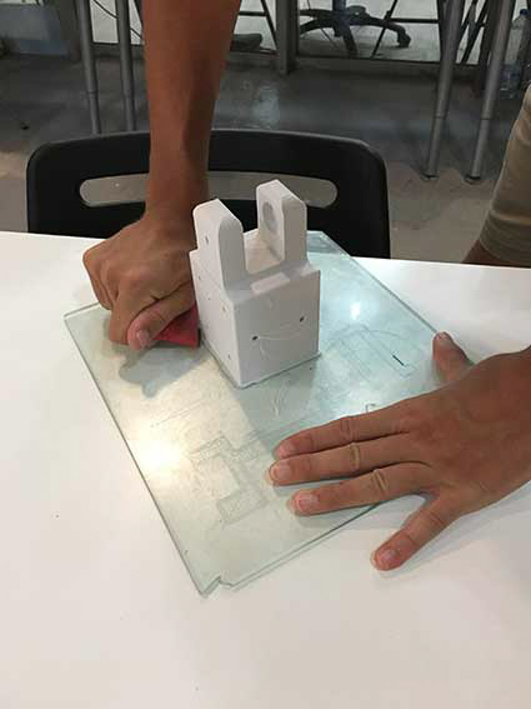
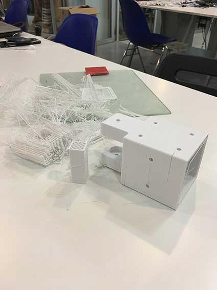
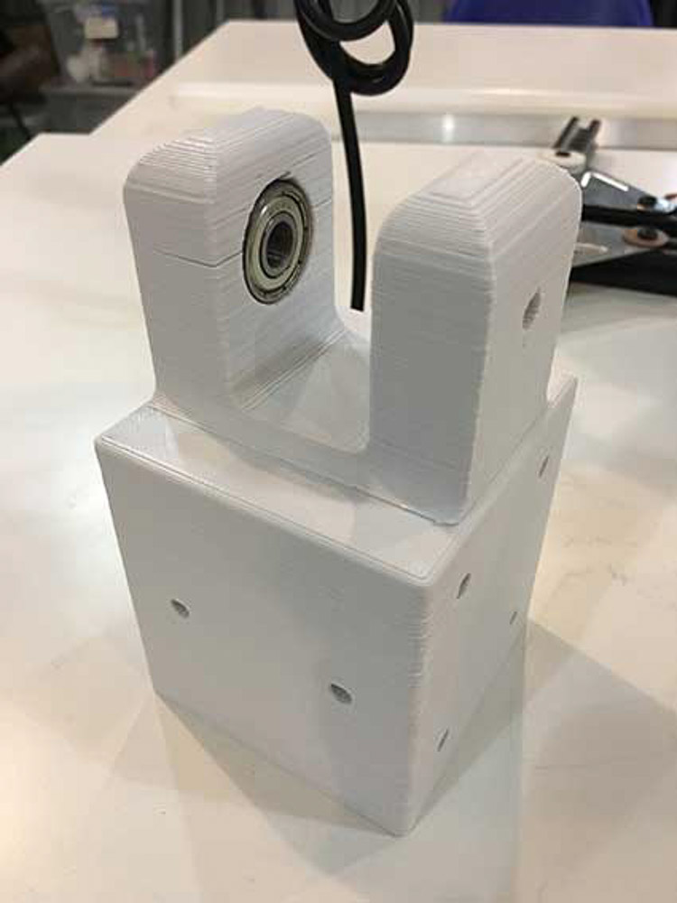
Unfortunately the above part turned out to be only really effective as a test concept. Sadly, although it was a good fit, when assembling the top part of the frame it fractured and broke. And was not really suitable to become a lasting mechanical fixture. Perhaps with time to make more refined 3D print settings, using more detail and a solid infill, this would change the durability and properties, or even try printing in an 'abs' or nylon plastic.
Due to time constraints, and wanting to use something suitably strong to securely fix to my metal frame structure, I will return to the metal plate fixing option. With more time and funds available, I could have purchased some aluminium sheet, and attempted to cut-out blank parts using the shopbot mill. Making more customised fixing plates for the frame structure according to my design specification.
For the time being I have sourced locally some laser cut aluminium plates in T - L configuration that allow easy assembly and provide bracing joints between the 't-slot alumium profile' pieces of my frame.
These will also provide the main hinge fixing point for the central coloumn in the design. For the other hinge I have found some door hinges that would fit the design and work relatively well! as pictured below, but I would like to use something much better and fabricate my own hinge blocks, or find something I could use like a die-cast alluminium block wich would be more hard wearing and in keeping with the design.
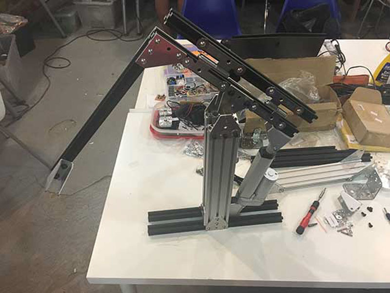
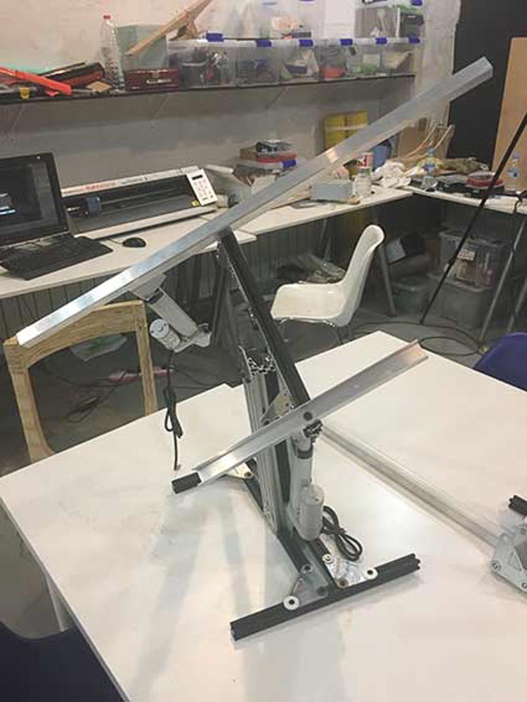
This is the progress I have made with the frame assembly so far...p>
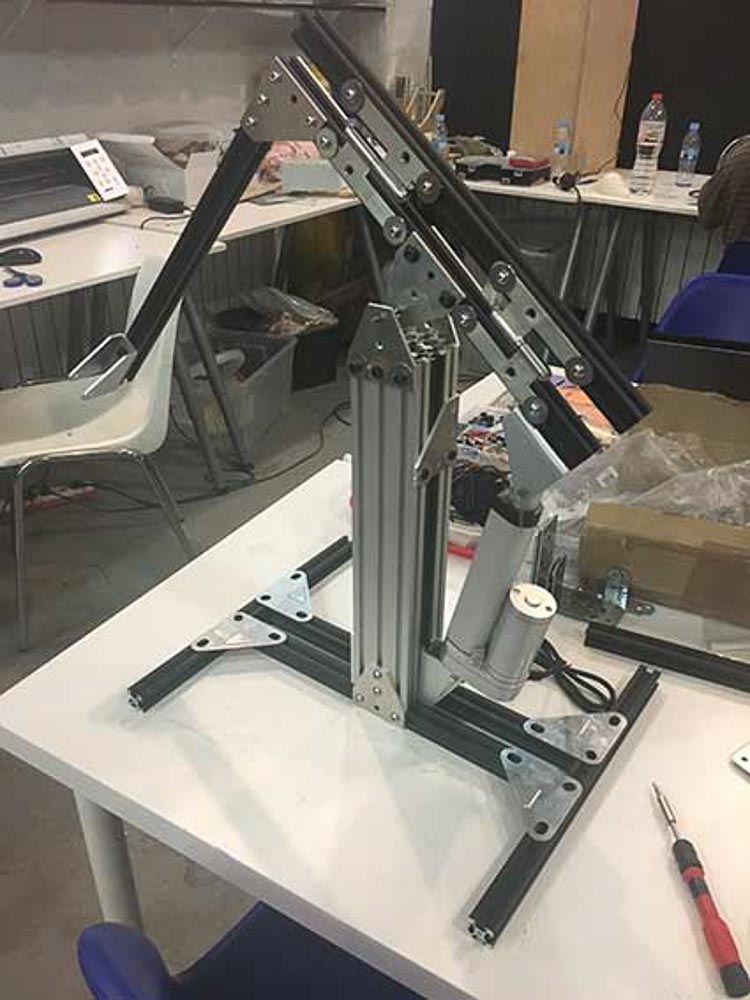
I have been frustratingly trying to source cheaper and more accesible stock or companies to purchase the appropriate T nuts and plate fitings for these alluminium extruded profile pieces. After the arrival and paying for some badly fitting pieces in the wrong size, and then re-measuring the frame sections I discovered that the 20x20mm section was a slightly different and non-standard slot profile width compared to the 20x60mm section that I was using. I decided to re-order more of the allen head bolts and special threaded t-nuts again online, and hoped this time I had now calcutaled correctly and in sufficient number to accomodate all the fixings on the design. The downside of this was the extra cost, delivery time and the wait! However, meanwhile I have been working on the electronics and testing the tracking motion.
I have since made another two further revisions to my control board to make it more of my own design. The first was in adding a 5th digital pin as it seemed easy and there was space to connect this. Less easy was then routing the extra analogue pins from the mocro-controller. I have tried to open up four more additional analoge inputs. By doing this I will enable attatchment and configuration for further digital devices such as limit switches or analogue joystick control. However, after tirelessly completing all the soldering of this board; I then discovered that in my trying to add a non fab-lab standard - 5pin header into my Eagle inventory and schematic for my design, the pins were then slightly narrower profile which prevented me from using the standard physical header components. After initially uploading a bootloader successfully and testing, I then had further troubles with this board, whilst trying to hard wire in these digital pins unfortunately there was some further damage to the board.
So I finally resolved to make a third and final revision in the hope that I could neaten up my design a little and come up with a final working board that I could program to use on my prototype tracker. This time I decided to be more adventurous and integrate the dual D.C. driver motor circuit into the arduino style IC control board. I spent a while in Eagle getting this to all work theoretically together in my circuit design. This is what I came up with.
After milling and soldering this was the outcome, and I was then happy to see a green and red light on the smoke test.
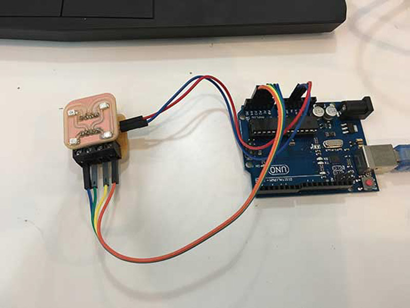
The bootloader seemed to burn with my FabISP programmer and then I went straight into testing the light sensor module with good results
However, when I got to connecting up the motors with auxiliary 9V Vbb power supply a little wearily, I got no response from the actuators. Returning to another sketch it seemed fine. Then to my dismay after further fault finding and testing later that day, the board strangely stopped working entirely, and would not upload a sketch. Returning the familiar error: skt 500