This week we will work together collaboratively in groups to design and make a functioning machine. We should have at least the passive parts resolved, ready and able to operate manually, in order to prove our mechanical concept by the end of the week! Eeek!...
This will include effective project management to be able to work cooperatively and independently on the different aspects of the design. Including analysis of technical aspects, mechanical function and control. Recognising opotunities for imporvement and refinements as we work toward our final goal.
We have decided to build a solar tracking system. Primarily and for now aimed at attaching to a regular type pv solar panel or reciever and tracking the sun's light throughout the day, to face a panel at a 90° angle. Such a system should increase the efficiency and maximise the amount of useable energy that we can harness directly from the sun. Alternative aplications for such a system might also include a 'heliostat style' parabolic - mirror reflector for directing sunlight onto a Concentrated solar reciever, or a lens for focusing suns light in a similar way onto a reciever, for instance in a solar furnace. Concentrated solar energy is a nice possibility, but for now we will work on a basic two axis machine.
Please also refer to my preliminary ideas and my subsequent final project pages for more research and development on this type of system.
We set to work organising our group, we are a team of four - Trinidad Gomez, from Mexico. Isaac Piere, and Jean Cristophe Thuan, both from France and myself an Englishman. Initially we started by looking for insight and relevant information and examples of what else had been done before, we were also spurned on and enthused by a similar project that was undertaken at Valldaura last year at the GreenFablab. Gregoire Durrens from this project even came in to give us his insights with a chat about how that project went for them. We focused on the details and mechanics being used on existing designs of Solar Trackers and came across several interesting variations, and posibilities.
We discussed potenetial management options for our group project. We agreed that Trini had some prior experience with using 'HackPad', so began setting up and creating our website for ongoing documentation and presentation of our project using this platform. Meanwhile we would manage ourselves and our project workflow by creating a document file on google drive to share our files and work on documents together. We are largely communicating, if not face to face each day in the lab, then via messenger in a whatsapp group we have created.
We began by sketching, sharing and assessing our early ideas for the project and laying out the basis for our own design in a group apraisal.


We can break down our machine project into its basic parts: a fixed stand or platform structure which allows for the mounting and support of a medium or standard -sized solar panel - rectangular in shape. This structure will allow the panel to have two separately driven axis of movement, one for East West - pan, and One for North South - tilt motion.
The aim then is to program this structure to automatically position the attatched panel to face the light source as directly as possible at a 90° angle, and therby track the sun's motion at set intervals across the sky by day. (Ultimately it should then reset and return to it's parked and initial morning start postion at night to save energy. The program and electronics can be restarted up the next morning on a loop timer.)


We have learnt that the electronic tracking can be acheived by using photo-resistors or LDR's. These light dependent sensors decrease their resistance according to an increase in light intensity. If we wire up and arrange four of these sensors in a fixed grid; with - North, South, East and West respective positions; and a cross shaped shade barrier between dividing them, so as to separate and define the amount light hitting each sensor at different angles.
These sensors will then generate data output based on light intensity, So we can then aproximate the position of the light source in front of them by taking into account the difference between these two pairs of values. This data can then be fed back to through our program in order to control the attached stepper motors or actuators which control the output position of the panel along for each of it's two axis. Essentially a kind of joy pad feedback for the motion control. Up/Down - motor A, Left/Right - motor B.
We had to make quick decisions for the basis or foundation desings for our structure this week, this was no small or easy task. We each had our own strong ideas and differing methodologies about how to resolve the problem and what to work on, everyone was conscious that there wasn't a lot of time. Early on we decided to devide our labour somewhat; two of us - Trini and JC would focus on the electronics, research into power and controll operations. Additionally sourcing and understanding relevant code for input and output devices. Trini also worked hard with early presentation and documentation of our ideas by setting up our website. Whilst Isaac and myself took more of a focus on prototyping the physical frame structure, creating first mackettes based on our sketch-work, demonstrating the moving parts and mechanisms involved.
I discovered there are a few main styles and mounting configurations for solar tracker designs in general. For Single axis there can be either Horizontal, Vertical, Tilted or Polar tilted panel mounting. And for dual axis systems usually a Tip/Tilt (TTDAT) system; where a T or H piece is mounted on top of a rotational bearing at the end of a pole which then connects to the panel from behind, these are typically aligned with a true north meridian, or east west line of latitude. Or alternatively an Azimuth-Altitude style (AADAT) system that has its primary azimuth axis vertical to the ground with the secondary elevation axis normal to the primary axis. Commonly these are supported by a large rotating ring or bearing. which can be extended to the edges to support and distribute the weight of larger arrays of panels.
The main decision this week was how to resolve our mechanics of these two rotating axis, and housing motors and attatching this all to a frame to hold a panel
It was noted that we would almost certainly be driving the movement of our tracker with motors and there appears to be three or four main ways of creating a drive train; by means of pulley and belt. Gear and Chain. Rack and Pinion. push/pull rods and levers or Linear Actuator lead screw. Although It was not obviously or immediately apparent how, or why one of these methods might be benficial over another. Each appeared to have obvious appeal and would work in some respect, but have their own complications in terms of technicality of their design mechanical relationships and physical properties, the ability to fabricate and easily test each prinicple was looking unlikely at this stage.
Essentially I would like to design something that could be functional or as near as possible and which could potentially be used in situation. It would be nice to see a design that could be scaled up and used practically with a fairly large and useful size solar panel.
Scale is quite an important issue as our design mechanically is essentially two rotational joints at stacked at normal to each other. The simplest approach might be something like this direct drive motor stack...I think these are bought for camera mounts on rc planes, heli's and drones.
However, in larger scale structures, when there is allways added load or lateral weight involved at either side of the pivoting part then there is obviously a considerable increase in the forces and unwanted stresses mechanically on the joints. This either has to be accounted for with beefier, heavier and stronger joints, or by introducing additional support structures connectors ties, or guide rails for the moving parts of the mechanism. With a solar tracker it is a bit of a design problem for supporting a large wide panel and still having two axis of movemnt. you would logically attatch it to a wide base with supports of some kind to it's outer edges to hold it securely. However, with a two axis system even if you were to widen two points of contact and have a hinge on either edge of the frame, you would still have to have the primary hinge joint at a central point underneath/behind to allow for full freeom of movement in the other axis. Perhaps this is why the extra complexity and cost involved in building 2 axis systems makes them less commonplace in large arrays.
A solar tracker should really withstand the test of time and the weather! come rain or shine it should be resistant to damp, moisture and damaging UV light as far as possible. And one of the biggest problems is the wind. When a gust picks up, a large flat panel tends to act as a sail and the forces subjected on the fixings and joints will again multiply greatly.
This is something I was trying to take into consideration in the initial design stages, whilst also fully understanding that we didn't have very long to resolve a mechanical outcome as a prototype. And then we must begin to engage with control and programing options for this machine. Needless to say, I began by thinking more along the lines of a having reasonably light-weight, but high strength aluminium box frame construction.
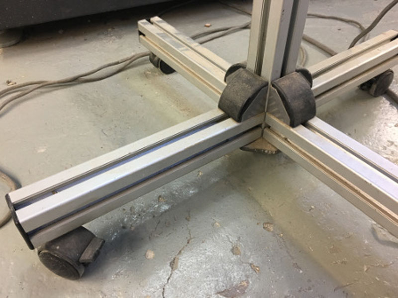
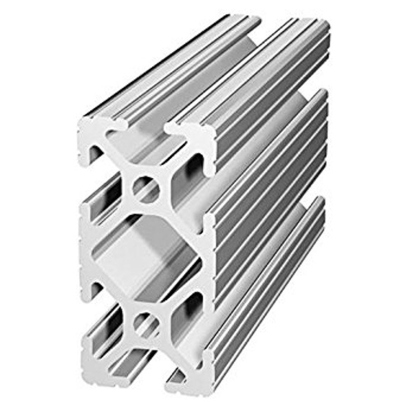
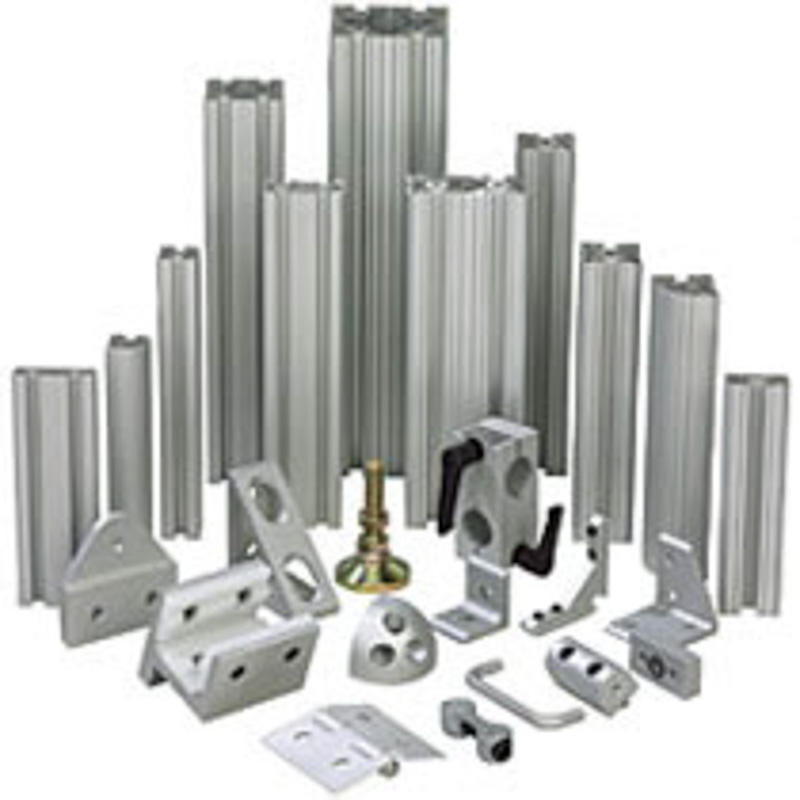
Inherrently this would effect the shape and design outcome from the start. We had some 1m 80/20 extrusion lengths in stock and handy in the lab. And so I started looking into this as an option for our frame. It is potentially viable to weld aluminium to make a box frame and joints, although I'm told it can be tricky. However, it wasn't currently set up for this in the lab, it was an idea for the future at least. Also the ease and range of potential fixings and fixtures for the 80/20 profiled aluminium section certainly displayed good promise for allowing us to alter positions of joints and adapt our assembly methods or attatch different modular parts at a later stage. It's stiffness also would make for an ideal frame. Although it may well cost quite a bit to build a full size frame from this material, it's definitely worth looking into.
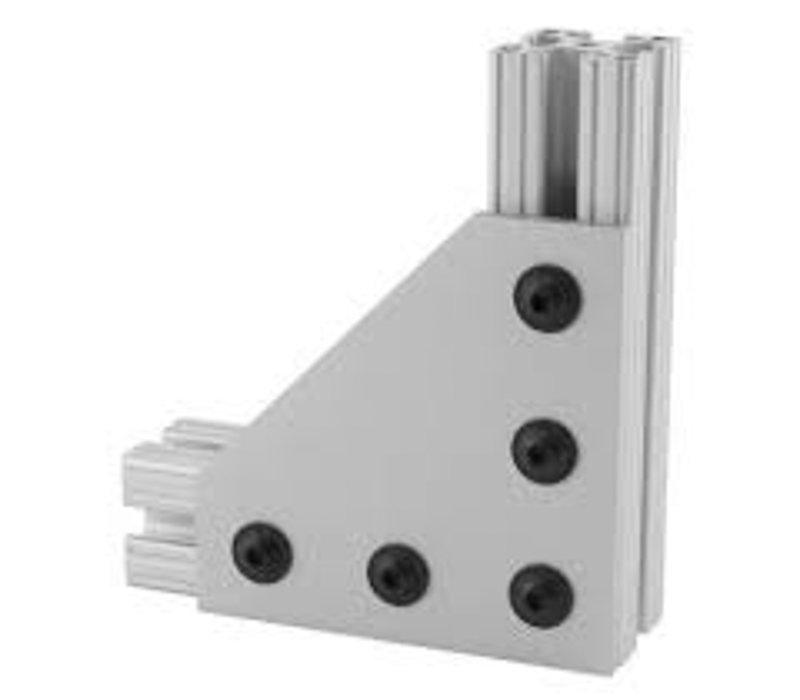
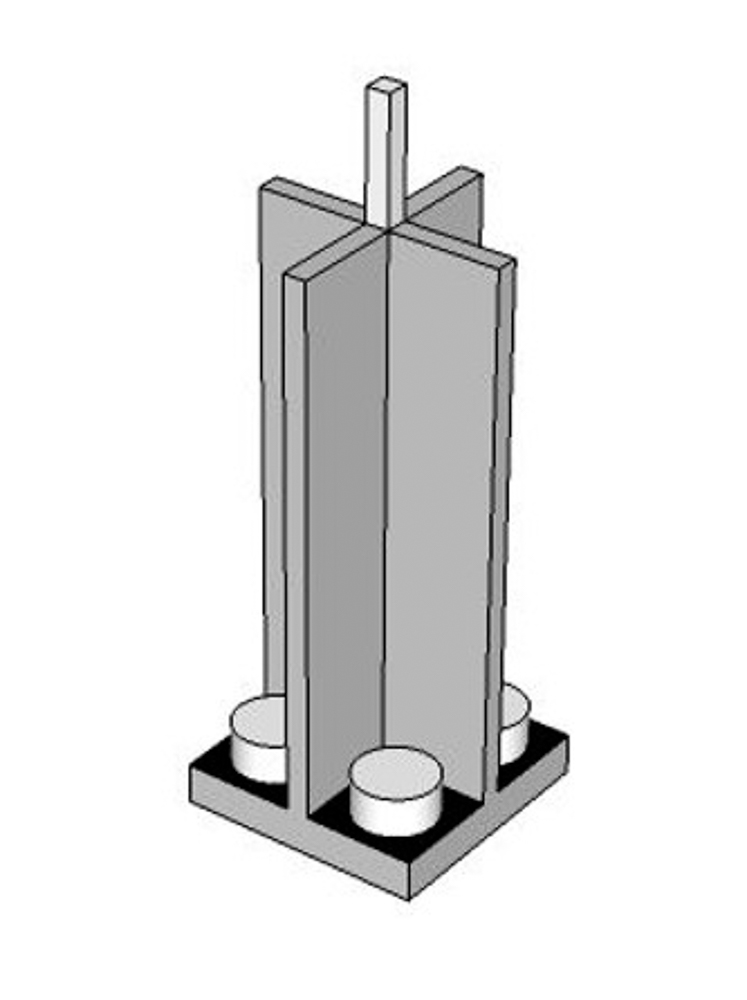
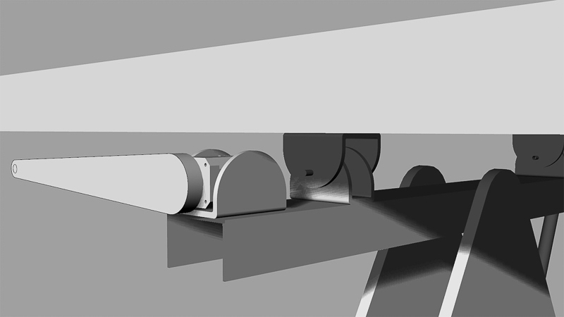
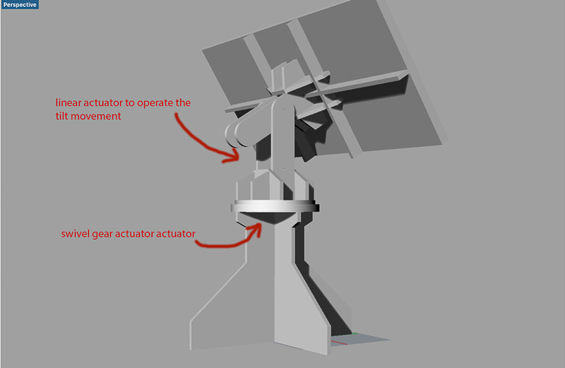
After some research, the design I had in mind would comprise of a strong single central pole as an upright section to get the panel off the ground. This would be supported by an sturdy base structure. Connected at it's top most point to an 'H' shaped bracket with a central pivoting hinge. Then an 'L' shaped cross-beam on its side would be mounted into the 'H' hinge bracket of the upright. and along the top surface it would have the horizontal hinge mounts in the other axis which then attatch to the frame of the actual solar panel to be mounted. The cross-beam can then be elevated along a vertical axis by a linear actuator connected to under the cross-bar and to the base frame by linear-pivoting joints. Then the lowest trailing edge point of the 'L' shaped cross-bar connects up and onto one of the horizontal edges on the frame of the solar panel to actuate the horizontal axis movement. I got modelling a small model on the first day, even though it differed to the idea that Isaac was pursuing, It would work somehting like this.

Isaac designed and cut out another test model on the laser helping us picture the frame structure.


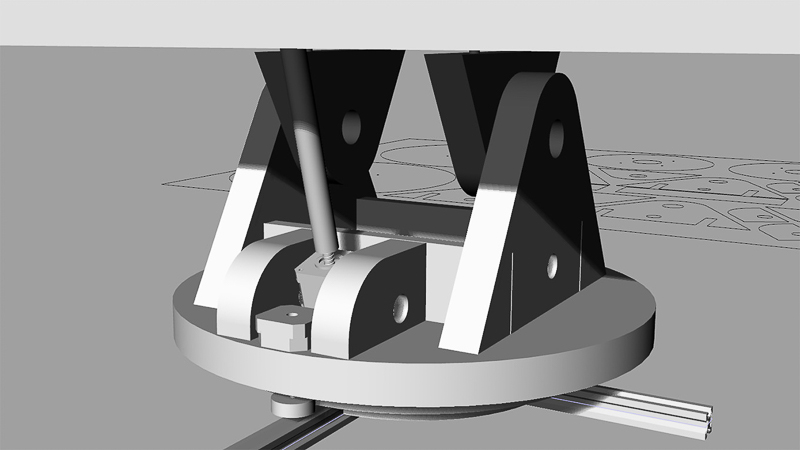
By the next day in the lab the main debate, mechanically speaking, seemed to be whether to use two linear actuators for both axis of movement, or just one for the tilt and have a rotary action for the base. This concept involves a platform rotating with metal a turn-table ring joint driven by a gear. Even to try and encorporate a pulley, or chain drive somehow would be an option to step down the gear ratio. I was also wondering about an over-sized servo horn lever shaped part on the motor shaft underneath the panel, which could then connected via linkages to either edge of the solar panel to give the rotational movement.


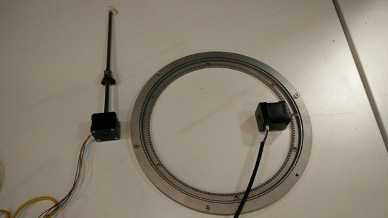
Our ideas were plenty and enthusiasm was high, but tensions were rising and we needed to make solid progress with our model. Maybe our technical knowhow and mechanical expertise was somewhat lacking, but this was all a good learning curve. Furthermore Isaac already had been able to source some interesting parts, bringing in a couple of metal turn-tables, and some skate bearings. First was smaller free moving version, and now we also have a larger more substantial part with a geared profile, one which we could definitely use for this project. - this part is typically known as a 'lazy-suzan' A metal ring fixing assembly that consists of top and bottom ring sections with ballraced bearings sandwiched between them. This can then be mounted to a top and bottom surface to form a large stable rotational bearing platform. It could be the perfect solution us!


After some early conflicting of design ideas and direction, we now really needed to push forward with one common resolution. We decided to move with a wooden frame construction for now, as that was most accesible to us and easiest to work with in the lab.
- axis number 1. -
We would intergate the 'lazy-suzan' and a geared stepper motor to provide a rotating base platform.
- axis number 2. -
We would then use the linear motion stepper motor, driving a lead screw and nut for the tilt motion. This needed to be fixed with rotating couplings at the base and onto the moving upper panel part to allow for correct motion up and down the shaft thus tilting our panel.
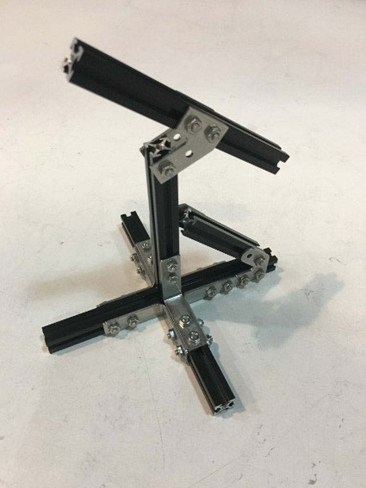
By this stage Isaac and myself had both done some 3D models with some differing design variations, so we made one further small prototype each of our respective designs, in order to evaluate and test out the basic working principles and form for our design.


Working along side us on the electronic side - Trinidad and JC were already making really good progress in researching the programming and breadboarding the layout for the motor control circuitry. We have ordered motor driver units and a CNC Shell from Pololo, to give us motor control using an Arduino board at this time. Enabling us to code and then drive the stepper motors.
First of all they programmed two servo motors and quickly progressed onto a stepper, which requires external power in the range of 5V-24V (+) Pretty soon they would have both motors up and running.


We also were optimistic that we might also integrate the photo-resistor sensors into our circuit and alter the code driving the motors accordingly in the following weeks, so as to move the structure according to the position of the light. For myself, I have been going steadily crazy studying about all different types of motor D.C brushed and brushless, stepper polar and bi-polar! How they all work and how one goes about controlling and programming them. During next weeks 'Output devices' assignment I aim to produce a stepper motor driver board and learn more. I have also seen that there are many types linear actuator motor available, prices ranging from similar to the NEMA 17 about $20 up to $60 for bigger length extensions and more powerful lift and pull capacity. The ones from China seem actually reasonably good value and I wondered about buying them for this porject.
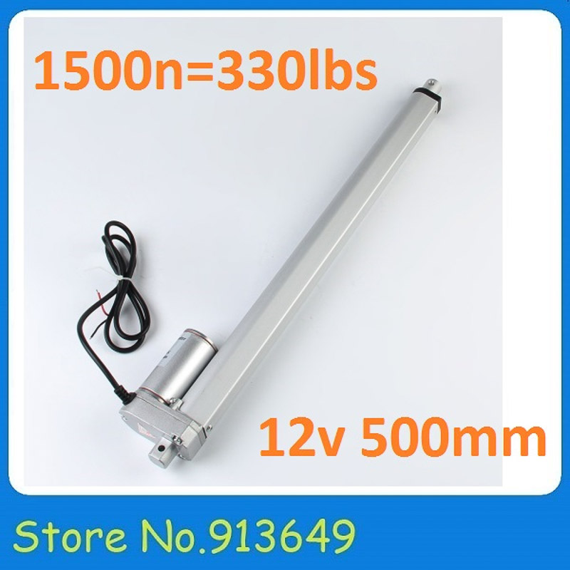
These come as fully housed units usually geared internally, they are available in various lengths and specifications and designed for the kind of powerful slower responsive push and pull movement we are after. These may well be ideal if we pursue the linear actuator route for our desing. And I hope to engage much more with the investigation of motor control and programming of output drivers next week. Since we already had the nema 17 stepper motors in the lab, part of our class order, two of which we had asked for had lead screws attatched. It seemed sensible and most logical at this stage to progress with the elevation axis of our tracker driven by a motor with lead-screw driving a lead-nut as a linear actuator connected to our panel.


Happy or not with our design so far, we now really needed to push forward and to mill some parts out in larger scale to be able to assemble, and then begin testing the motion and mechanics with our motors in place. This would be the essential design and motion for our frame...
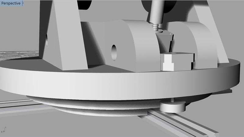
In order to fit our motors we did undergo a few attempts in designing some 3D printed motor housings. However, we had varying success with these parts. We were encountering ongoing problems with the print set up and achieving a good consistency and quality of our 3D printed parts. There was also a worry about the overall tensile structure and strength of these parts, and whether they would really be useable in our design. The motors would need to be securely fixed in place and would also undergo quite substantial forces when under load, their mounting needs to be solid. For the rotation of the base motor, it needs to be fixed and locked at the correct height and position within the base frame, so as to allow the pinion gear on its shaft to mesh with our lazy-suzan teeth. The correct pinion gear also had to be fabricated to to drive and turn our lazy-suzan gear.
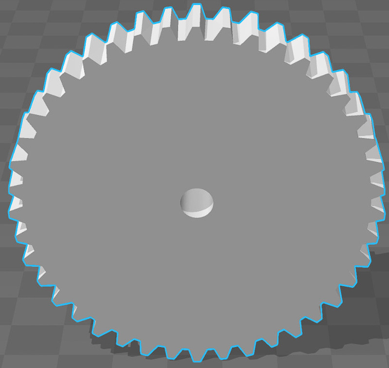
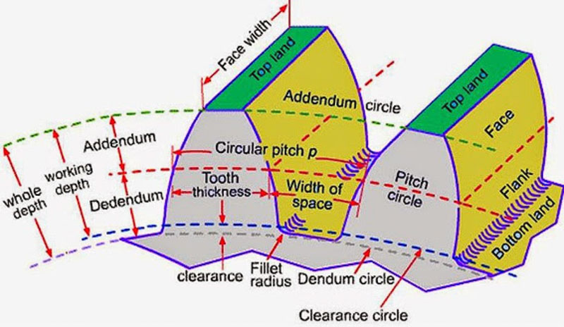 gear nomenclature
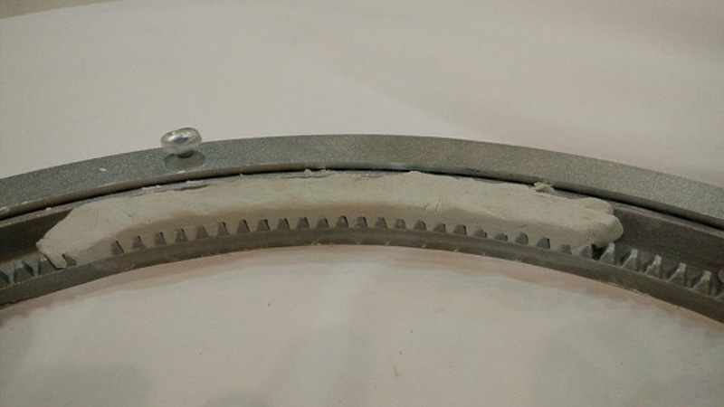
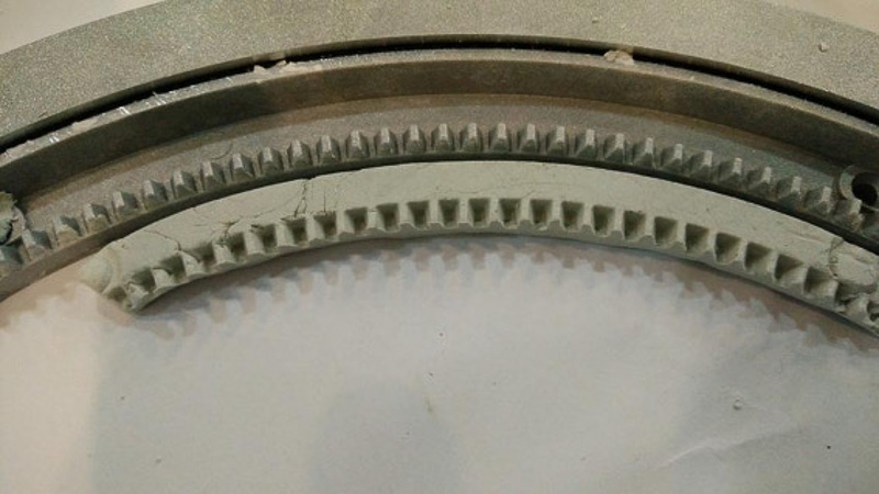
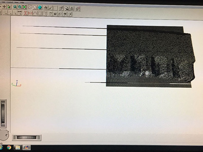
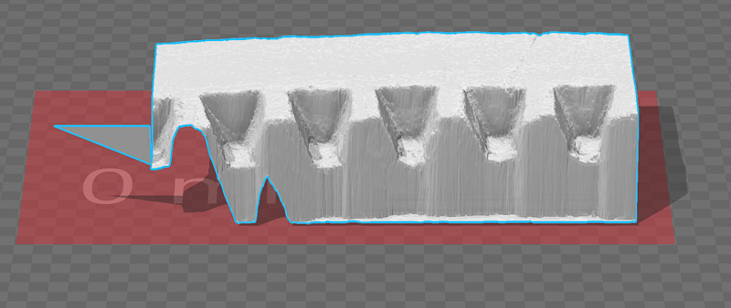
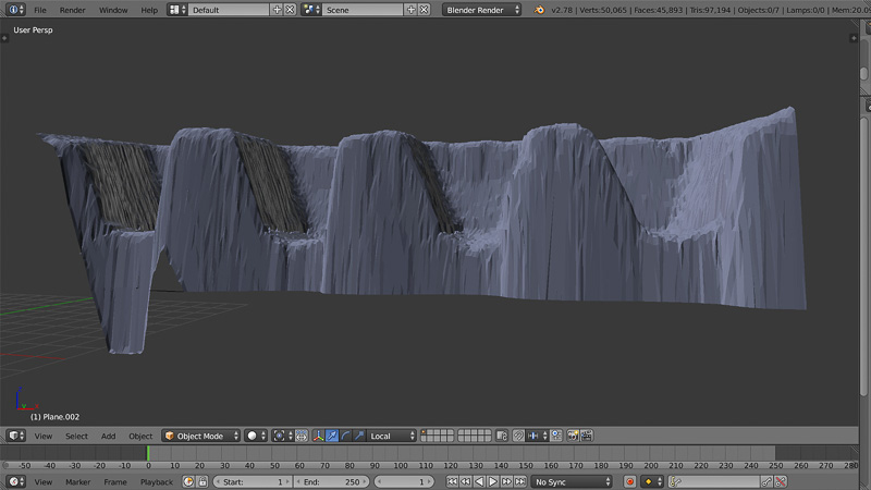
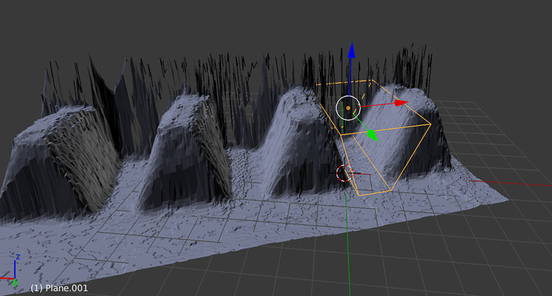
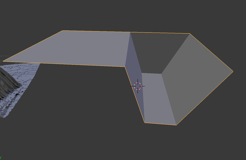
J.C. had been experimenting by roughly estimating the gear profile and generating some potential gear wheels using online gear generators to make a generic profile then 3D printing it to see if we could adapt the profile and then get a better matching mesh for our lazy-suzan tooth profile - but this seemed a bit like trial and error. Then we had the idea that perhaps we could make a 3D scan of the tooth profile on our gear. We made a plasticine impression of a section of teeth on our gear. Then we set up to use the Roland MDX-20 modella to make the scan. Eventually, this process gave us a point based mesh of our teeth output as an .STL file, which we then imported into Blender. We had some help using blender from Victor who knows his stuff in this program. It was apparent that the scan couldn't easily be cleaned and shaped into flat surfaces so we re-modelled a section of a few of the teeth from this profile making a positive form to use. Then we rotated this section in a polar manner around a circle to create our solid test gear part. Adding manifold edges and a grub screw fixing for the axle attachment.

For the linear motor: a simple box housing with a hinged fitting at the rear then bolting to the the frame platform was the idea, with bearings would be nice. Then another hinged part attached to the lead nut/shaft and fixed to our lever for the tilting panel.For the top motor housing and assembly it needs to be attatched at both ends with a bracket to some effect, and yet still have linear rotational freedom to account for the change in angle as it moves. I got to work designing this section and came up with this design..

I was trying to encorporate added guide rails on the sides of the lead screw to give extra support, as had been suggested by our workshop technician Martin. My eventual printed parts for this assembly and for our gear turned out like this.


Unfortunately along one axis depending on how the object is aligned when printed there is a shear weakness between the layers. A thin wall thickness in plastic is not that strong without extra support or webbing. As I found with my motor housing when the wall easily broke away during testing these parts. I would have to learn more about finding just the right settings on the 3d printer to get a more quality end result. At least we had a functional gear part which seemed pretty tough and durable. And we would no doubt use this in our first working prototype as its tooth profile now meshes perfectly with our lazy-suzan gear.
The next stage was to mill out our frame in full size, in order to test the joints angles and mechanism of our prototype design with stepper motors attached, and then begin the tasks of signal control and programming.
In order to have a functioning model machine working in just a few weeks for this itteration Isaac's frame design was our choice of direction, more details of which can be viewed on his page. We will cut this out using the shop milling machines of the most economical and readily available material in the lab the 15mm low-grade plywood sheet.
Please see the continuation in Week 11 for the culmination of our group machine project. For now back to Outputs understanding motor control - Hbridge drivers and programming motion based on our light sensor values.