

Please refer back to our Previous Progress at the start of this project on Week 9 Mechanical Design - - -
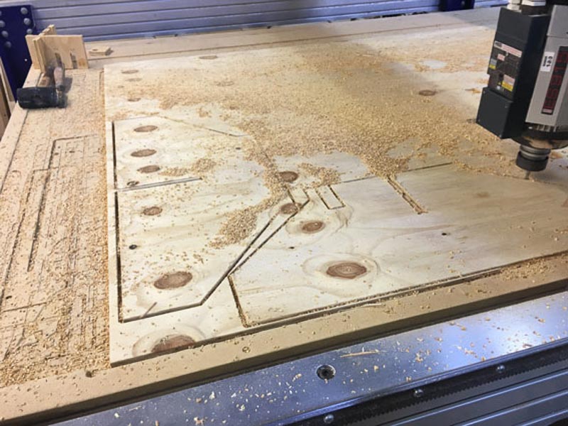
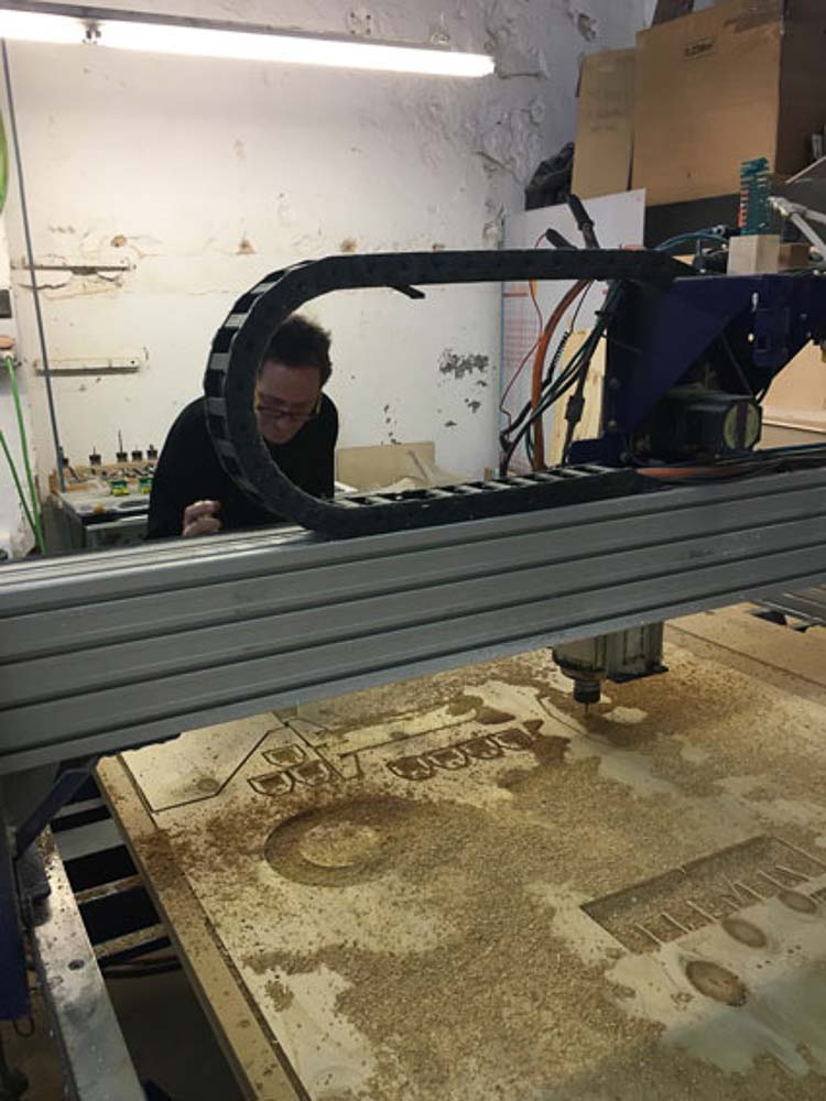
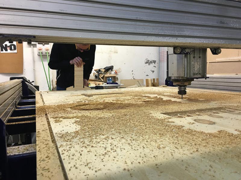
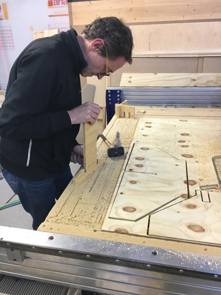
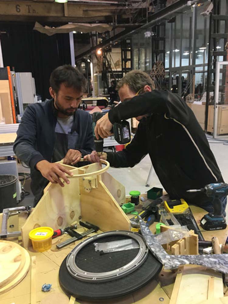
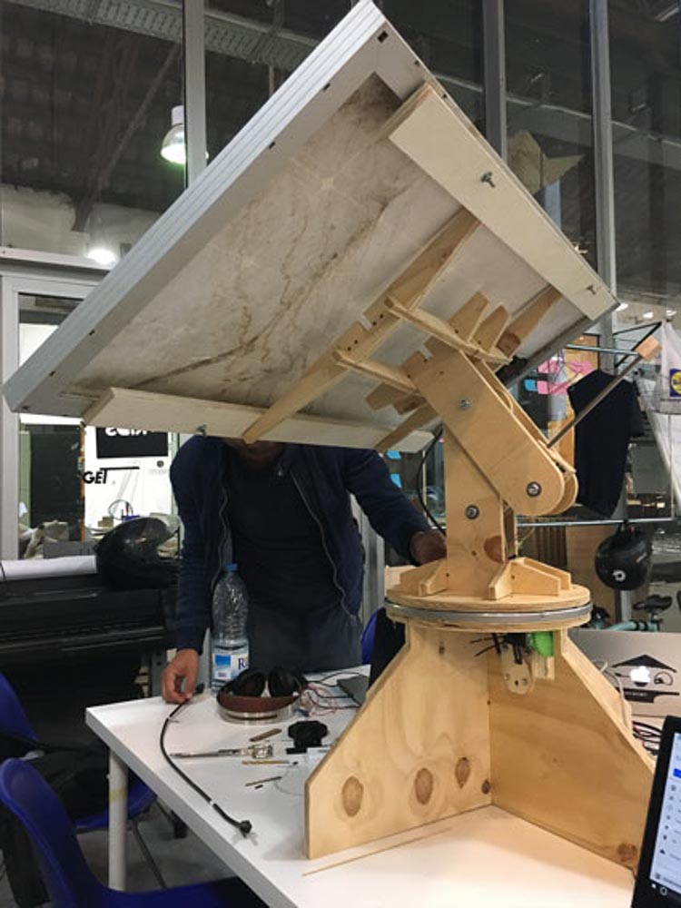
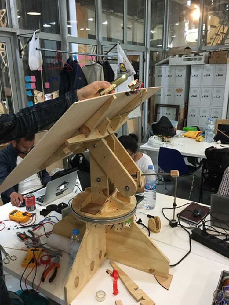
After first doing some test cuts to test the tollerances of our joints and push fit parts, we then began milling out the wooden frame parts for our tracker in 15mm plywood. Using RhinoCam software to generate the tool-paths and g-code before sending to cut on the Shopbot table mill. All the parts cut out reasonably well but did need some extra finishing, chisseling and tidying of the edges. Some of the parts thicknesses and design will need improving and strengthening so as to hold the eventual load, but for now it is a viable wooden prototype. We quickly worked together to assemble our parts making first the base attatching lazy-suzan turn-table. Then positioning and cutting a slot and bracket to hold the motor that for now we strap with cable ties and utilises little shims so we can adjust the height of the motor to correctly mesh the pinion with the main gear. Then the top frame was slotted together, also waffle contstruction it first needed to be drilled to equip a bearing for the Main tilt motion hinge, and to make holes for the other two hinge points where the actuator attaches. After the failiure of the 3D printed parts, Isaac was quick to come up with some simple and effective parts for mounting the linear drive motor. It needed to be fixed on top of the rotating base, and the lead nut that travels up and down the motor's screw needed connecting to the lever or tilting top panel part of the frame. He fashioned some some simple wooden blocks into a 'U'or'C' shape around the motors, then then bolt these assemblies within the upright side parts of the frame to create hinged parts.
Prototype Fabrication Video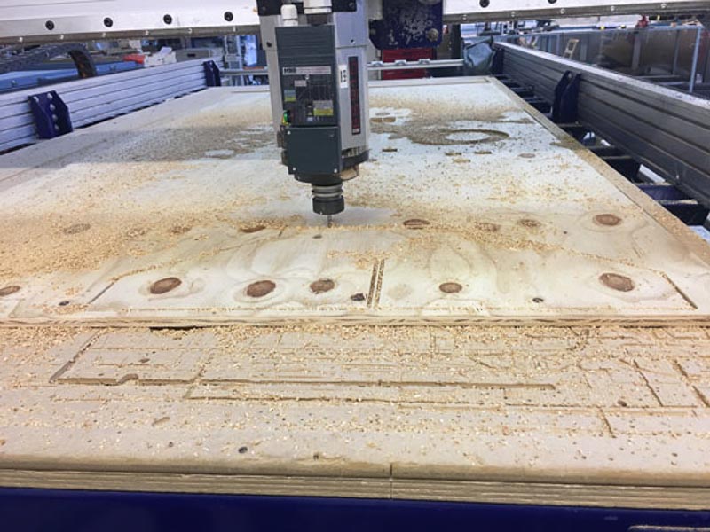
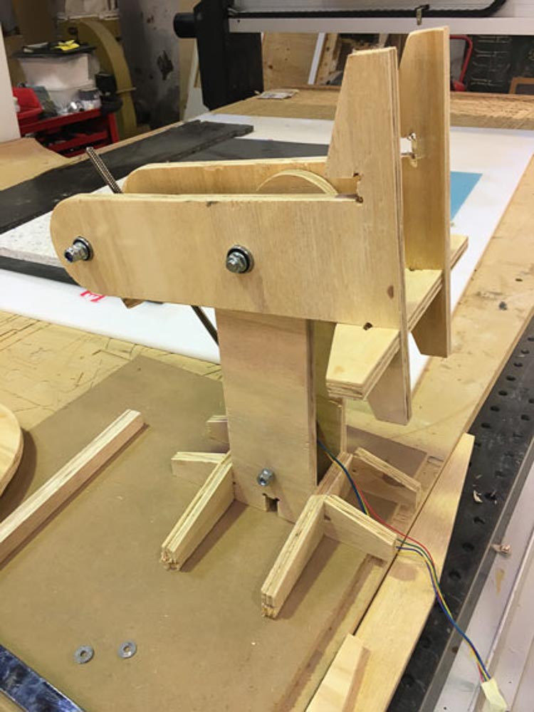
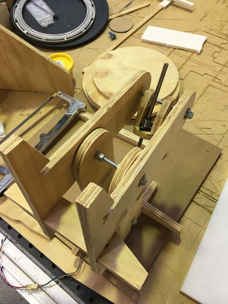
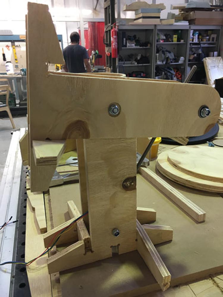
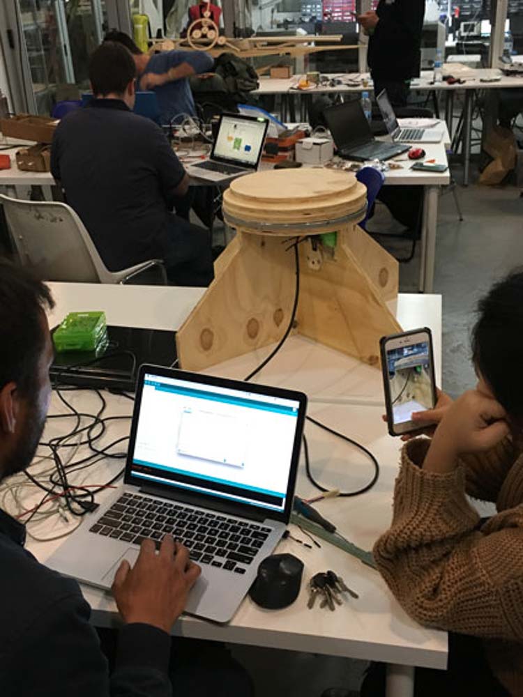
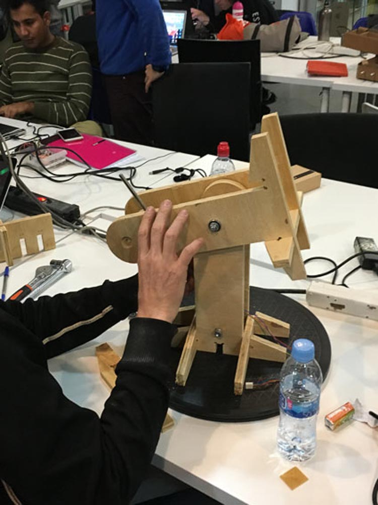
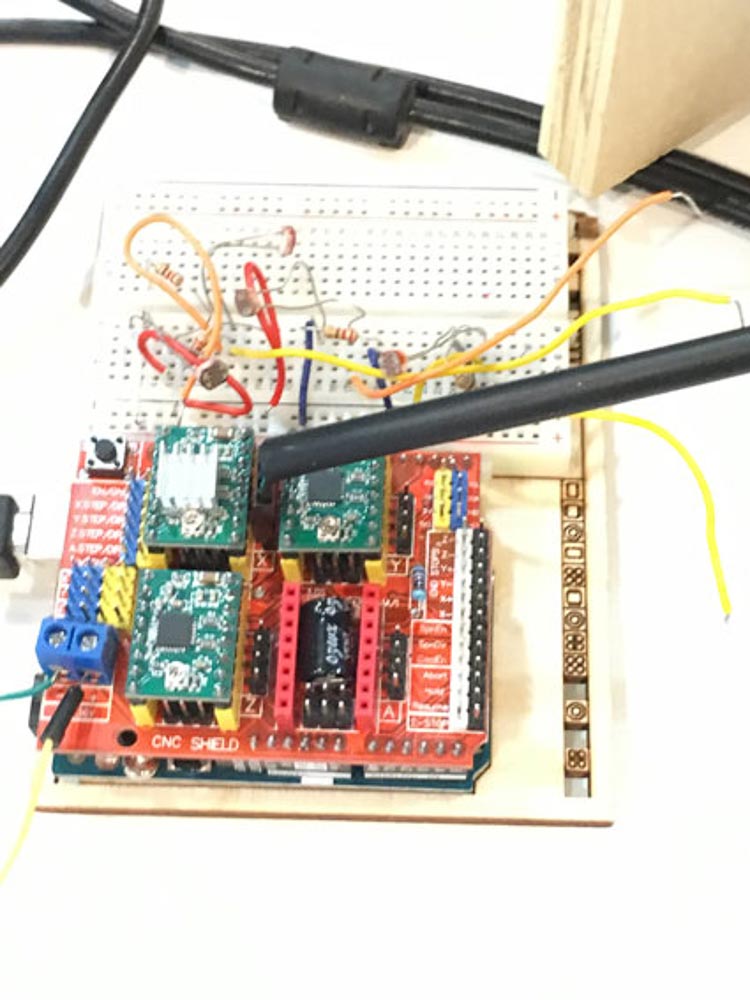
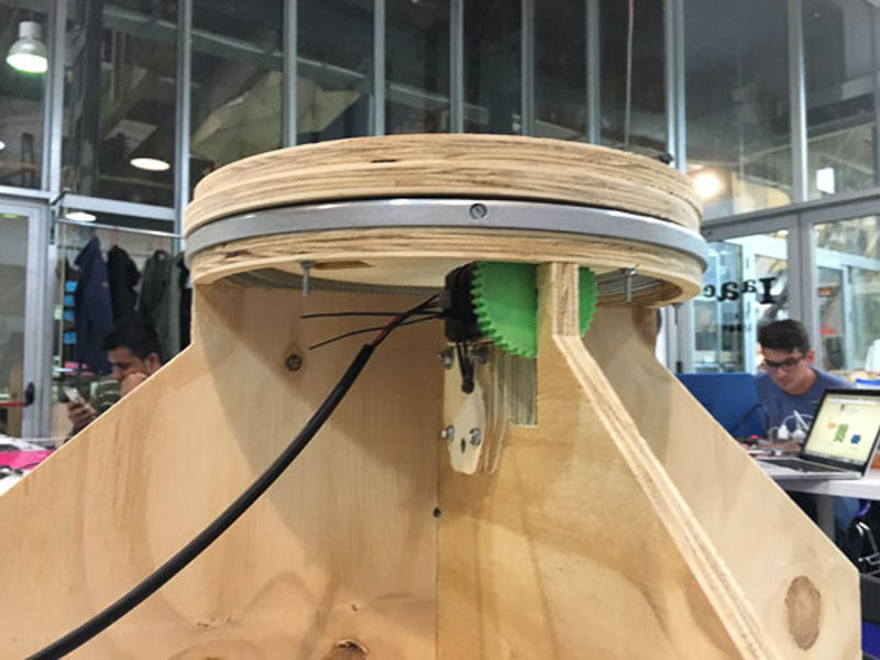
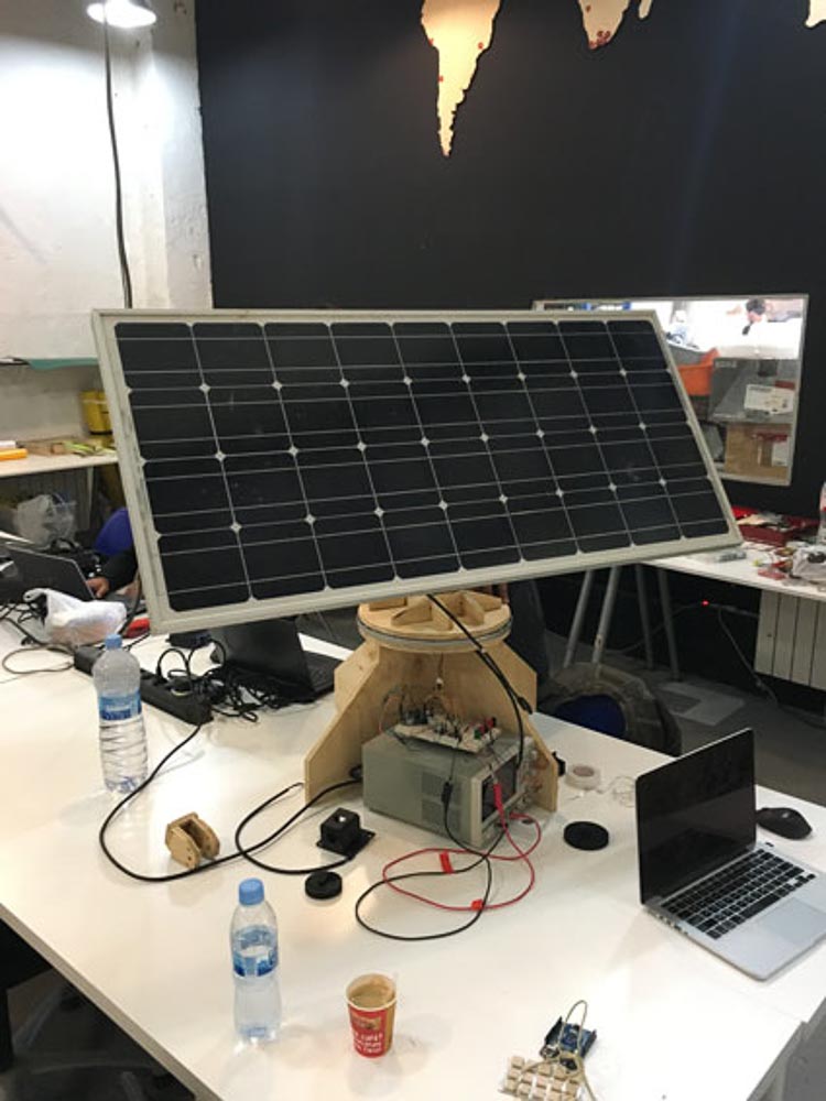
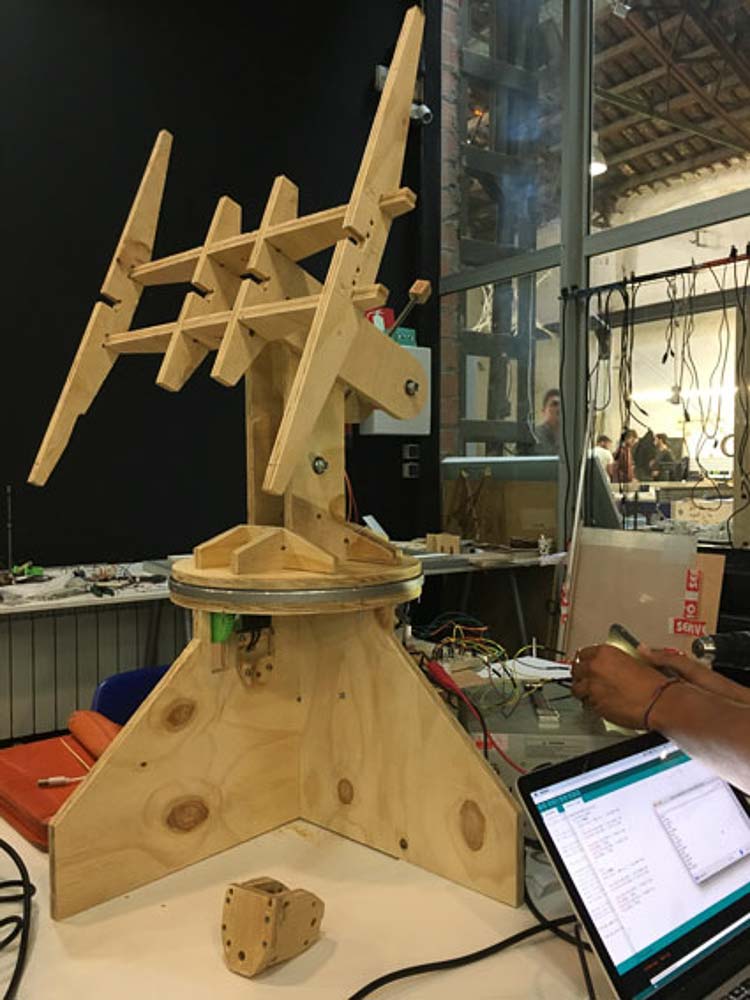
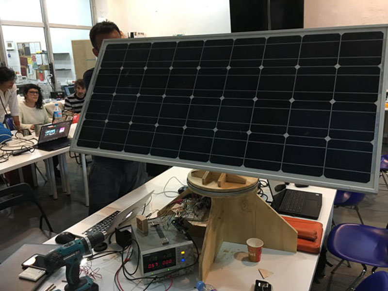
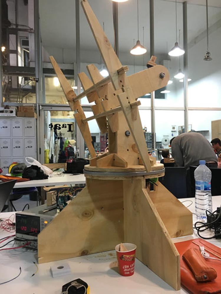
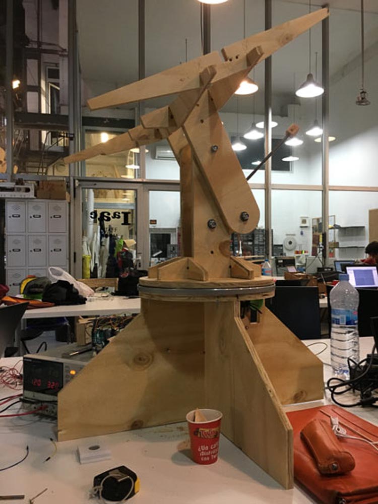
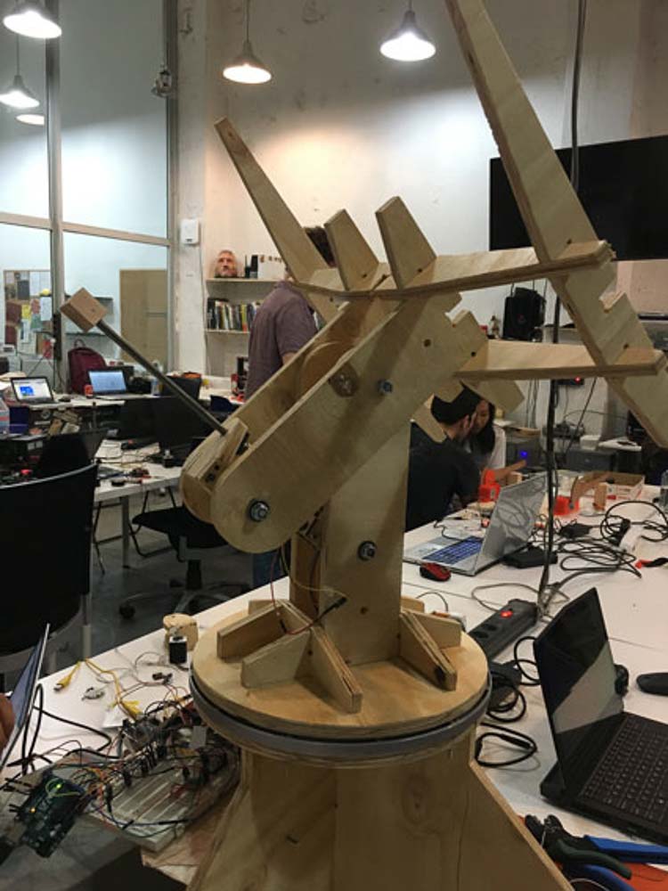
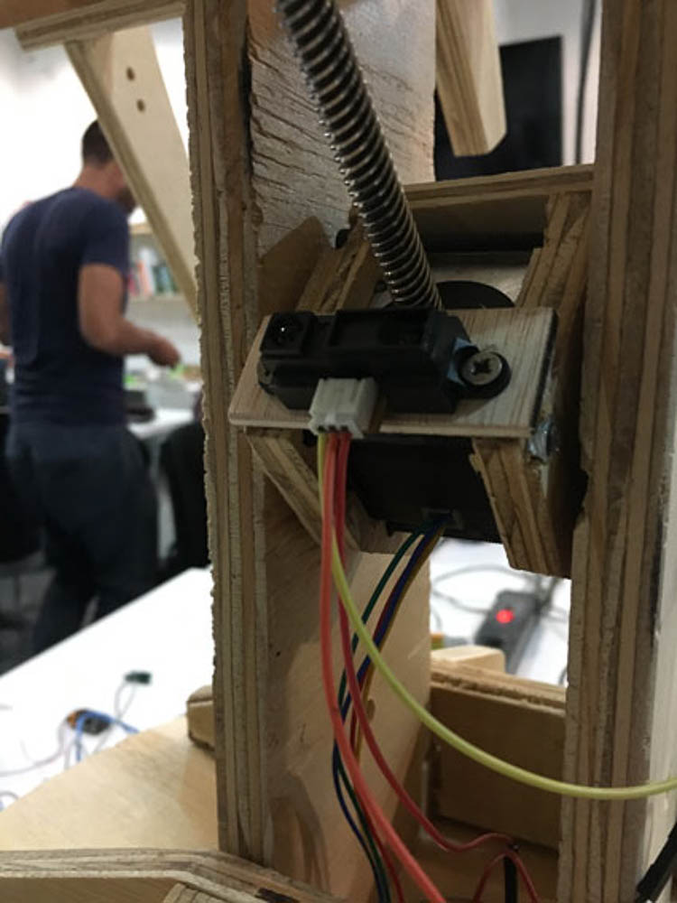
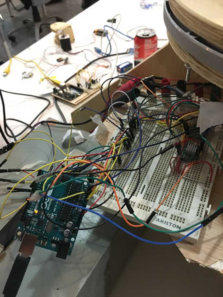
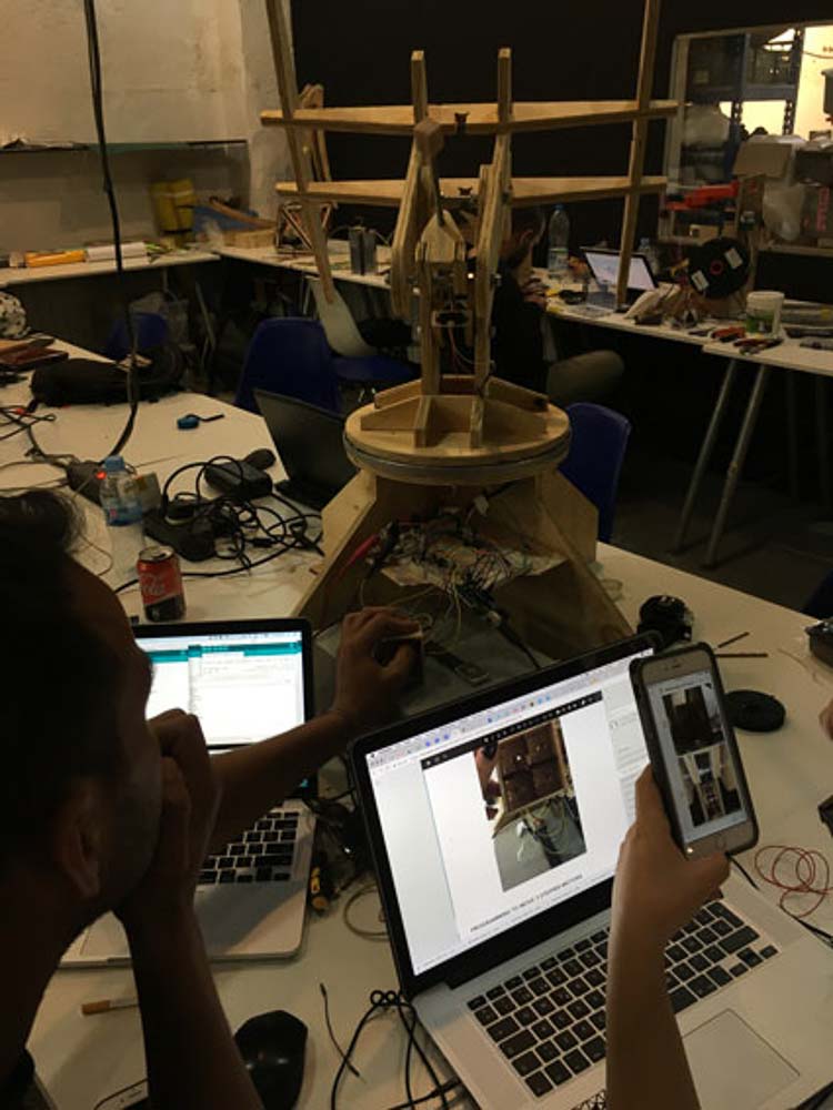
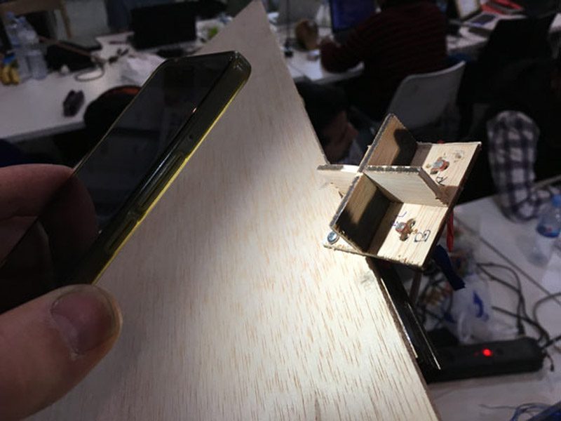
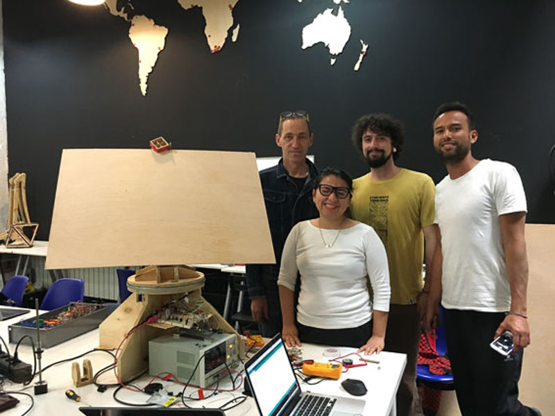
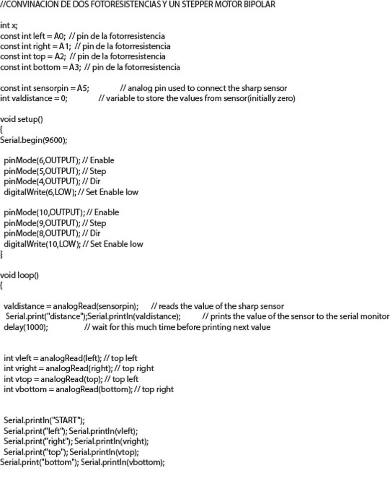
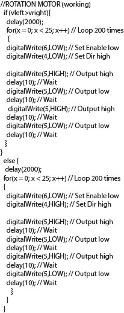
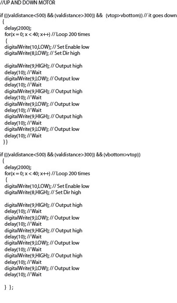
We have since spent a lot of time tinkering with the timings and code in order to get the movement correctly working with our light Sensors, and we are going in the right direction. We managed to get as far as wiring up a distance module to limit the linear action of the tilt screw motor. Some form of limit switch is neccessary to stop the motor or return it to a prior/designated position if it reaches the mechanical limitations, or the machines extent of movement. Isaac and myself also modified the design of the led division holder. Making note that by placing the light sensors closer together and angled at 45° outward would increase their effectiveness and sensitivity to the differentiation in direction of incoming light. It would be nice to refine our code and I certainly aim to understand more by continuing working on this idea. The ultimate next stage and goal would be to go onto designing our own circuit board for the elctronics. We also need to improve the sensitivity and response from the light sensors, probably something that needs further testing and component analysis. And we should try to smooth out the motion and steps of the motors. It is fairly noisy and also seems to jerk and shudder in its motion a bit. This is the code that we currently are using for our program...
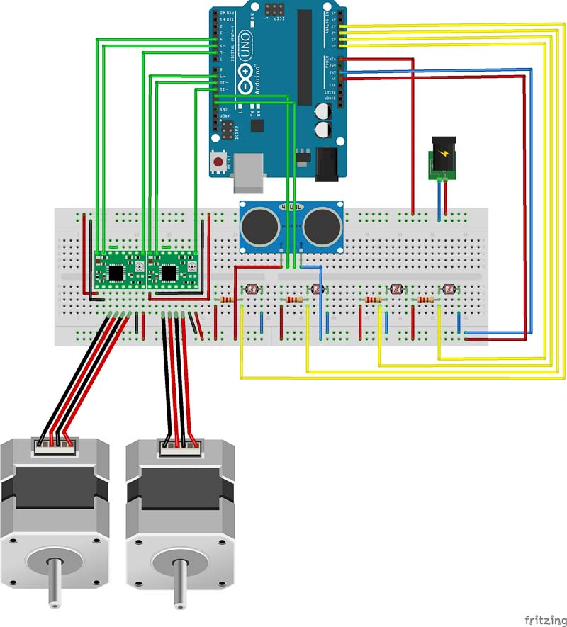 Fritzing Circuit Breadboard Diagram
When under load with the heavy solar panel mounted on top, the linear driven tilt motor becomes overloaded and struggles to move the weight. Possibly the placement and pivot could be adjusted, It may well be a different drive system or even a stronger motor could be a better solution. Alternatively, light weight flexible solar panels may be a good option.
We have worked together this week to create a video, an image board, along with our website and photolibraries to document and present our work.
We now have a working moving design that goes some way to fullfilling our initial design brief. It has taught us much and I would like to move forward with further itterations of this idea for my main project.
Project WebPage