

In this assignment we enter the world of programming and embedded systems. This relates to coding, circuit design and microcontrollers. An embedded system is a small integrated computer system with a dedicated set of functions within a larger mechanical or electrical system. These systems control many devices in common use today.
Also to point out that embedded programming differs from full OS-based programming where one may see on a computer. At the core of this control and electronic wizzardry is the microcontroller!
A microcontroller has the ability to control and sense its electronical surroundings. It can be used for monitoring and displaying data from various sensors or input devices. And also controlling by way of power, various output devices. As we become more familiar with their use and programming we will be able to integrate these to make all manner of projects possible. Microconrollers come in many different forms, varieties and specifications. However, they are available from just a few core families and manufacturers, generally speaking the most well known of which are; '8051' created by Intel, 'PIC' from a company called Microchip, 'AVR' from the company Atmel, and 'ARM' a UK based company. Each different architecture and model will have different features, capabilities and characteristics. Things such as speed, memory, power consumption, bus width, registers, instructional sets, cycles and timings, as well as physical connectability.
This week we will be programming our Hello_Echo ATtiny board that we designed and made in week 6 - Electronics Design. And we will take a more in depth look at AVR range of microcontrollers, on this board we are using the Atmel - ATtiny 44. By reading the data sheet for this microcontroller we are able to find detailed information about its specification, design, function and architecture.
Atmel AVR ATtiny DataSheetOur aim is to then program our board using the FabISP programmer that we made in week 4. And I truly hope mine functions as it should do! If not we can also use a commercial programmer, the USB AVRISP XPII, available in the lab in order to flash and then write some simple code onto our chip. We have added a button and an LED to this Hello circuit, therefore we need to make our board do something in relation to these simple input and outputs. There are many different programming languages and environments that can be used to acheive this task, we should explore and try to learn and understand some of the different approaches.
Looking through the data sheet for the micro-controller AVR AT-tiny, in its entirety a most substantial document! Certainly not light bedtime reading, it could easily put you to sleep with its technical complexity and detail!!
Data sheets however, are essesntial reference points, that povide key technical data for any component or device you should wish to integrate in a design. Very useful for feature finding and referencing things like pin layout diagrams, so we can identify correct pin connections for labelling in the schematic and designing the layout of new circuit-boards. Reading through the datasheet in more detail is helping give me a better idea about how functions and instructional commands, timings and how memory is organised within the chip itself.
As far as my understanding goes so far, the physicality of the ATtiny 44 and other micro-conrollers is that they are like a mini computer in themselves. Divided into a series of boxes and functions controlled by a central processor unit. They are able to run through a set of instructions that you give them in the form of a program. Key functions of the CPU are to store, access, and process data in cycles according to a clock frequency. Timings are clocked in Mhz by an internal or by an external crystal resonator or oscillator. the ALU - Arithmetic Logic Unit section, handles the logic and mathematical calculations. Cache memory is where a small amount of memory is allocated in order to store and execute the program. These core parts are connected together via an internal system bus - an instructional wire arrangement. Data in binary is sized in bits and stored in the memory. The memory stored is divided into program memory for boot and application Flash. Eeprom memory and Data memory.
The microcontroller memory is further arranged into small packets of information called registers and these in turn into banks - We have General Purpose Memory and Special Function Memory...
The microcontroller has a notch or small circle on the corner to idenify pin 0 and its orientation. There are a number of potential physical pin inputs and outputs. You power it through either a battery, USB or other form of 5V power (although some chips and circuitry commonly run on 3.3V) There are pin assignments for power -VCC and ground -GND, and a reset, and a number of digital input and output pins. For our At-Tiny 44 there are two such banks; Port A PA0-PA7 providing 8 x 8bit bi-driectional ADC analogue/digital pin Input and Outputs, tied with internal pull-up resistor and Port B. you will find programming pins for the serial peripheral interface or SPI. Serial Peripheral Interface (SPI) is a synchronous serial data protocol used by microcontrollers for communicating with one or more peripheral devices quickly over short distances. It can also be used for communication between two microcontrollers.
With an SPI connection there is always one master device (usually a microcontroller) which controls the peripheral devices. Typically there are three lines common to all the devices:
I will be using the Arduino IDE software or - Integrated Development Environment to code the mircoprocessor on my board to start with. This program itself is based upon 'C' language but it is more simplified to script in and it has some nice features and lots of good support available. Also it includes some nice example libraries and code to get you up and running and start modifying and making changes as a beginner. I downloaded and installed the arduino IDE software and added support for the AT-tiny 44 processor. Making sure to have the right FTDI drivers also installed to power the board via a USB - FTDI cable to your computer. Also checking that I have the correct drivers and my programmer is working in this case my FabISP. Then within Arduino IDE you first need to burn the 'burn bootloader' and Flash the initial program information Via your FabISP to your new chip. This will ensure the microcontroller is internally set up, identified and ready to then upload further code and program it to do something. First ensure to select the correct board - ATtiny 24/44/84, As we are running an external 20Mhz Clock on our board we will need to set this option too. Then set Port number for usbserial to your board and the Programmer type - fab tinyISP or AVRISP. Connect the ISP to your board via 6pin then Plug in the ISP, and also plug in the board to the computer USB ports. Finally you are ready to send the first program.
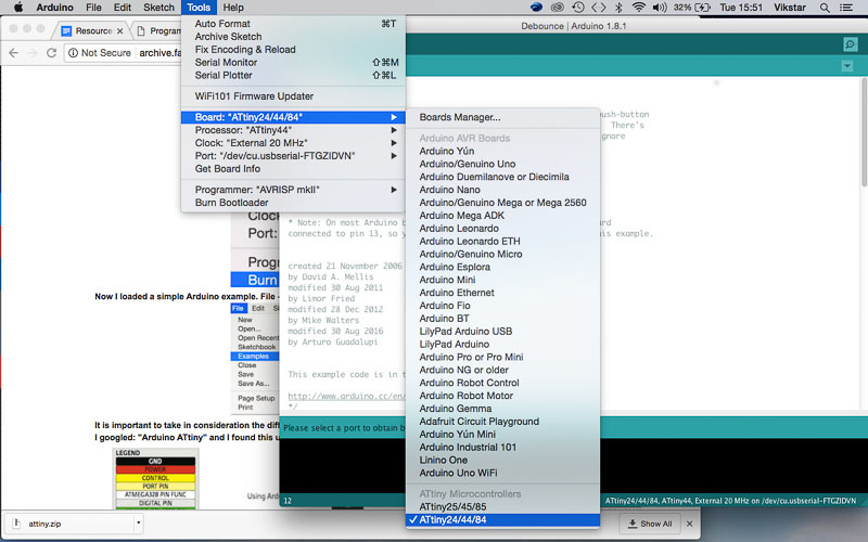
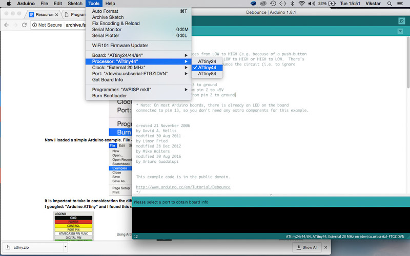
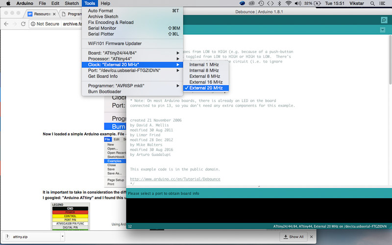
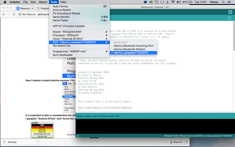
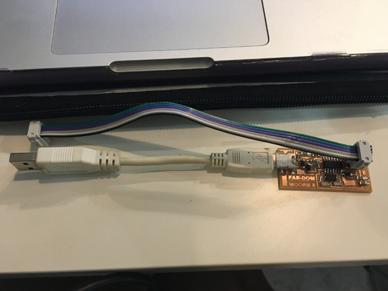
At first I got nothing!
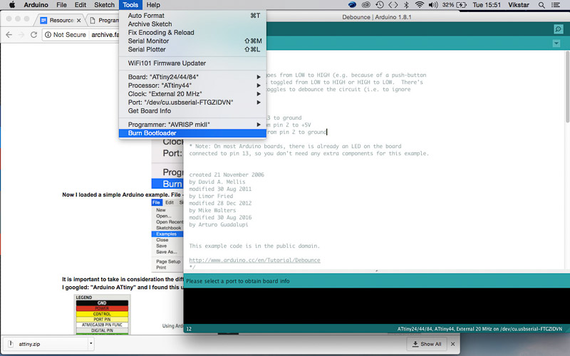
After much relief I did manage to program my Hello_Echo ATtiny board with its integrated LED and button successfully, finally I got it to blink back at me!! I was also happy that my fabISP programmer was holding up to the task. Initally I did encounter troubles and there was some confusion for me as to why it wasn't working at first. I wasn't sure if it was my fabISP, so I swapped this out and tried again with the AVR RISP programmer which wouldnt work either. It did seem like the code I was sending was getting through ok from the Arduino IDE, and through the computer the fab isp, and FTDI USB ports both identified ok. Eventually I identified the SMD mount around the LED itself as being the culprit, by tracing its pins and tracks on the board with the multimeter. I then confirmed this by adding an external lED accross the connection points and it worked and started blinking. I tried replacing the LED but it still didn't want to work, again it worked with an extenal wire LED. I ended up changing the surface mount over two more times! and it still refused to work with the onboard surface mount LED! annoyingly whilst trying to rectify things and clean this area some of the copper pads and traces began to lift away from my board. I ended up triming down an LED and hard wiring it onto my board so at least I could have a go at the programming tasks for this assignment.
For programming I began by adapting a few of the basic example coding files built in to the Arduino IDE, reading through each to try to indentify and understand sections of the code and what signals were being sent. I first managed to get the LED to blink, I then altered the speed of the blinking. I then moved onto the fade program, and played around with the button and bounce code also until I managed to get my switch to turn the LED on like a latching on/off function and also with a push to make or push to break switching function.
Hello World -Programming with Fab ISP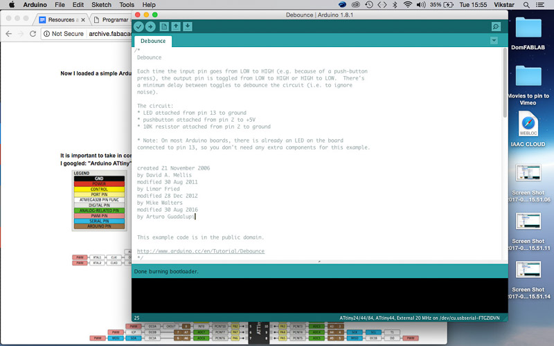
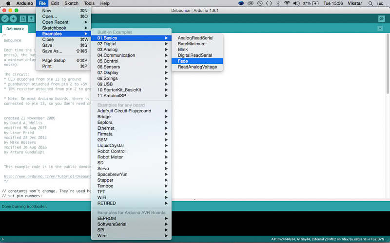
I am looking forward to output devices and input devices and more possibilities of ways of sending and recieving signals and data and embedding electronics in our projects to sense detect, display or control motion with our circuits. I would love to understand better the core C language and am starting to explore others. As the course progresses I hope to become more confident in understanding the basic syntax and some of the differences between the core coding languages. The different applications and strengths and benefits for integration in the design process and final project.
For now understanding the Arduino IDE and how to use it to program and communicate with our circuit board to get a response has been a great experience, and a basis for futher exploration and playing!