| HOME | ABOUT ME | FABLAB UPM | FINAL PROJECT |
| week 1 Principles and practices, project management |
| week 2 Computer-aided design |
| week 3 Computer-controlled cutting |
| week 4 electronics production |
| week 5 3D scanning and printing |
| week 6 electronics design |
| week 7 computer-controlled machining |
| week 8 embedded programming |
| week 9 molding and casting |
| week 10 input devices |
| week 11 composites |
| week 12 output devices |
| week 13 networking and communications |
| week 14 mechanical design, machine design |
| week 15 interface and application programming |
| week 16 applications and implications |
| week 17 invention, intellectual property and income |
| week 18 project development |
| week 19 project presentation |
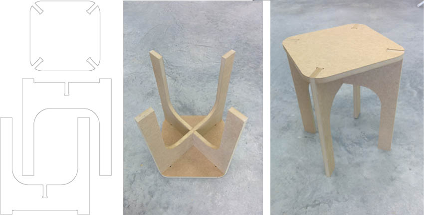
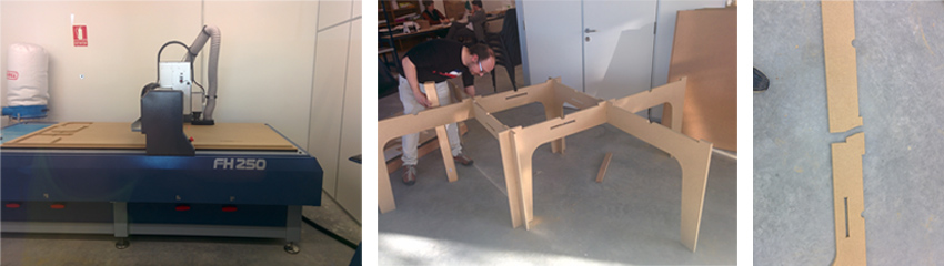
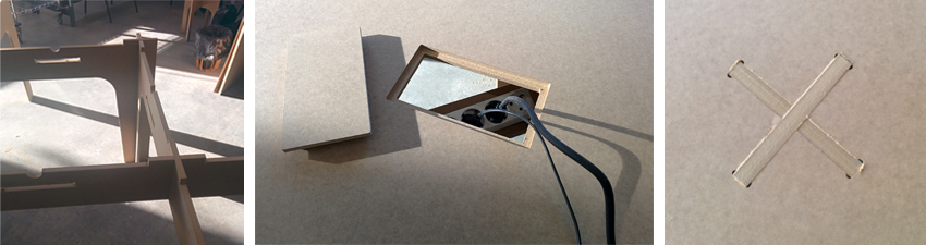
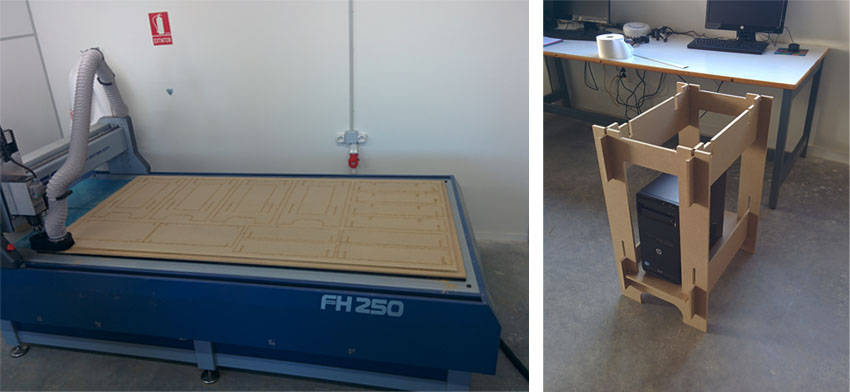
Week 7: Computer-Controlled Machining Assignment: make something big Goal: make two pieces of furniture that we can use in the Lab using milling cut without glues or fasteners, the piece must be stable by design. This weekly assignment has been made half to half with Ignacio Prieto, instead of making a piece of furniture each, we made two between the two. The material we use to make the furniture is wooden planks of MDF 16 mm thick. Machining has been made with a medium format CNC milling Alarsis FH250M, cutting dimensions 2,44 x1, 22 meters. We have used a 6mm diameter End Mill. First try, testing joints Before making the final furniture, we test the system making a stool, make by two pieces in X and a top board for sitting.
The system consists of adjusting joints to prevent movement of the parts and provide stability. The tolerance given to the joints was 0, so the assembly is more difficult but the parts remain fixed without using binder or screws. The result of the test is a stool which is stable even when you stand on it.
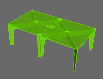
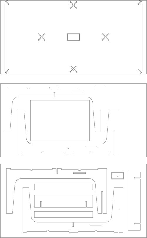
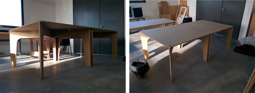
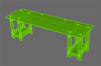
First Furniture piece: worktable This first piece of furniture is a worktable for using in the fabLAB where the top board is supported and serves as an anchor on six legs formed by four pieces that intersect each other to provide structural stability to the table. The board achieve to stiffen the assembly and give horizontal stability.
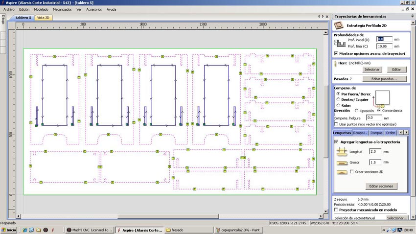
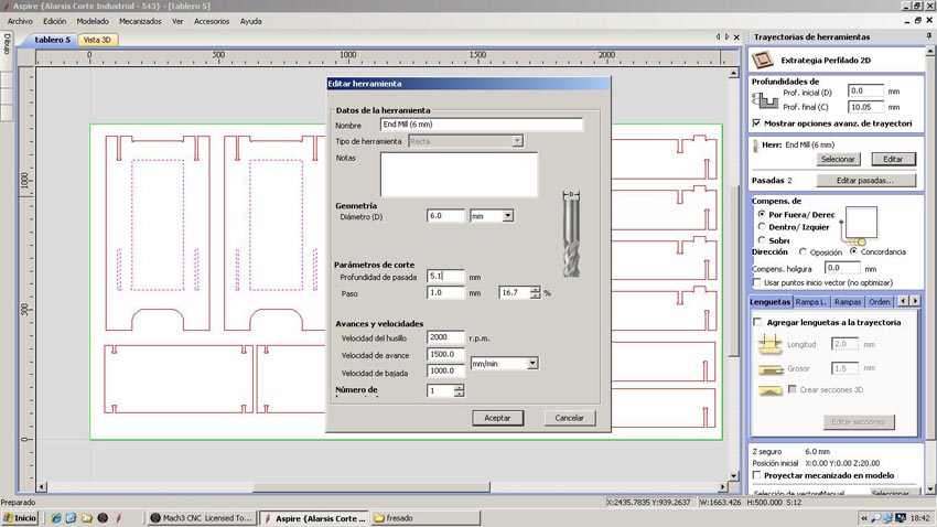
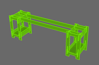
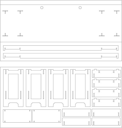
The software used by the CNC Machine is the Aspire. In the example images given, the pattern match to the second piece of furniture, but the cutting parameters are the same except for the thickness of the material, instead of 10 mm is 16 and and the number of passes is 3 instead of two. The first thing we do at Aspire is to define the dimensions of the material (2.44x1.22 meters) and thickness of 16 mm. Import pattern cut from CAD in .dxf format and now we choose how to cut each line, selecting, indicating the depth of cut, if cut outside, inside or over the line and add tabs to hold the parts while cut and prevent movement and mill break.
We select the tool that we will make the cut. In our case it is a Mill End 6 mm in diameter. It is important to select the right tool because in our design the corners have been done with a tool 6mm thick. The Mill expels chips compressing down and preventing cut pieces move. The speeds chosen were 1500 to advance with a depth of 5.4 mm to make the cuts in three passes.
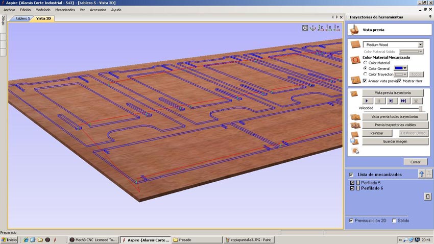
After selecting all the cutting parameters we check that the machining is what we want (the image shows the machining of the second piece of furniture, which has only two passes because the material thickness is 10 mm) and export the G-code in .txt format. The code associate parameters for all the motion vectors and machine speeds, etc.
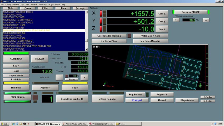
Open the G-code into the machine controller. We use the Mach 3. In this controller we calibrate the 0,0,0 point in the material and we are ready to start milling.
After milling we make the first assembly and discover a design mistake, the junctions are so narrow that avoid some of then turn to get the right position. When assembly we did too much force and break a piece. The solution was easy because of changing the direction of one union is easily mounted without problems. Also assemble the top board and we have the finished piece.
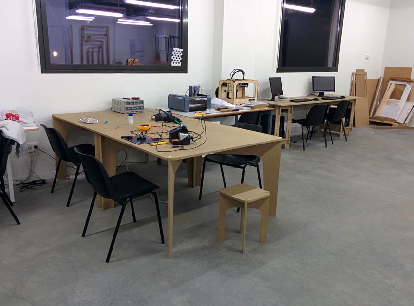
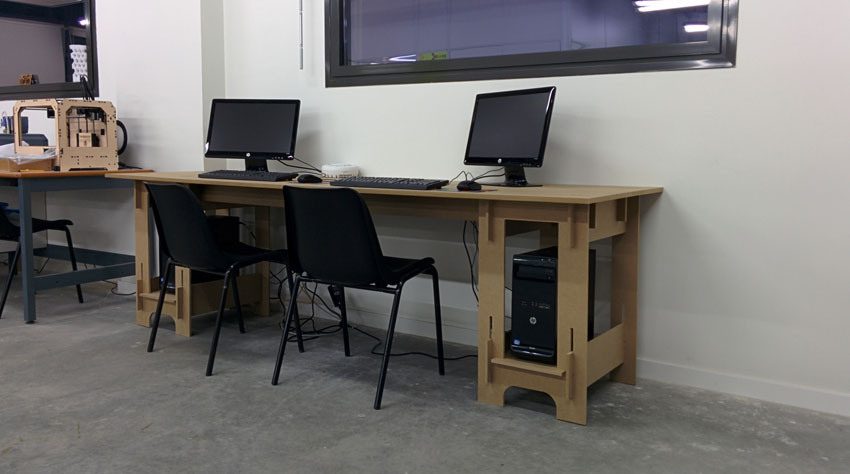
Second Furniture piece: computer desk Now let's do the second piece of furniture consisting of a desk to place the two computers for public use we have in the FabLab. The assembly system is very similar to the previous table, but the board used is 10 mm excluding the top board and the two beams that are 16 mm thick for added structural stability.
We perform machining of parts with the Aspire software and cutting with the Mach 3 as we have seen with the previous model.
|