| HOME | ABOUT ME | FABLAB UPM | FINAL PROJECT |
| week 1 Principles and practices, project management |
| week 2 Computer-aided design |
| week 3 Computer-controlled cutting |
| week 4 electronics production |
| week 5 3D scanning and printing |
| week 6 electronics design |
| week 7 computer-controlled machining |
| week 8 embedded programming |
| week 9 molding and casting |
| week 10 input devices |
| week 11 composites |
| week 12 output devices |
| week 13 networking and communications |
| week 14 mechanical design, machine design |
| week 15 interface and application programming |
| week 16 applications and implications |
| week 17 invention, intellectual property and income |
| week 18 project development |
| week 19 project presentation |
Week 5: 3D scanning and printing Goal: design an 3d print and object | 3D scan and object
|
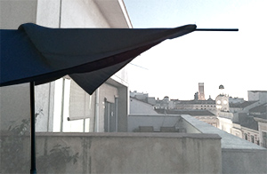
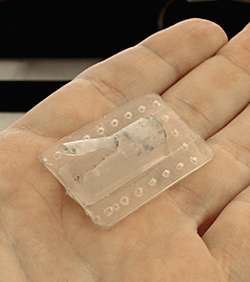
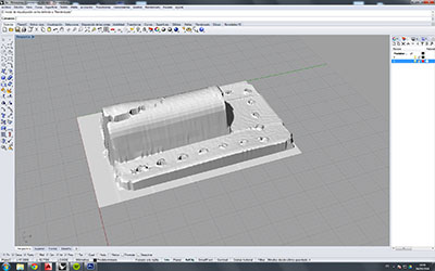
STEP 1: Separate the broken part of the umbrella and scan it in 3D
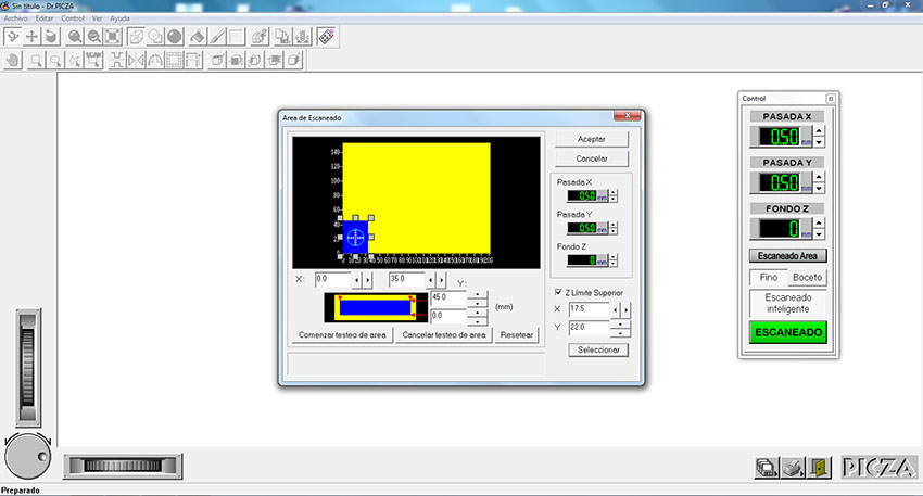
In the software we chose the scan area to reduce the scan time by limiting the area where the piece is placed. As my piece is small, the limits are 45 mm in Y axis and 35mm in X axis. Now regulate the separation of the steps in X and Y to detect the scanned points. The problem with this type of scanner is the time it takes to perform a scan. A closer spacing means more accurately but more time scanning. For such a small piece (45x35x15 mm), making separation of 0.3 mm step, the scan took more than 4 hours!!! So I finally chose a 0.5 mm step and the scan spent 1 hour. To reduce the scan time I manually indicate in the software where the highest point in Z axis is to avoid wasting time scanning air. In my case this point is in 17.5X 22Y coordinates.
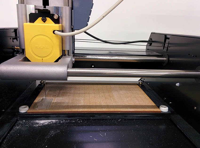
Problem: In the first scan, I had problems putting the piece directly on the base surface of the machine because the scan sharp end did not come down to the base and I lost the lower part of the piece in Z. To fix it I had to use a base of 3 mm thick and so I got to scan of the entire piece correctly.
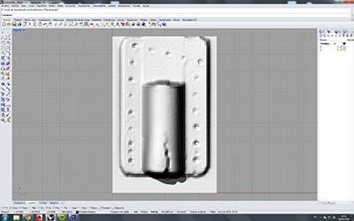
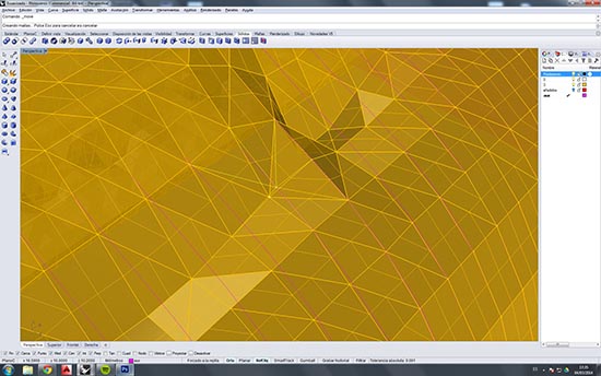
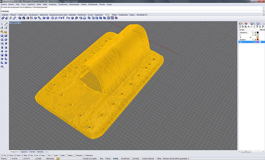
STEP 2: Edit the digitalized piece by CAD Scanning the piece we get a 3d mesh that can be opened directly in a 3D CAD program. I used Rhinoceros 3D, opening the exported file from the scanner software in dxf file. In the two images below you can see the mesh of the piece just as scanned, the scan imperfections and broken parts of the original part appear in the digital piece.
I modify the scanned piece for three reasons: - the scanned the piece has all the problems the original piece had, that is, we can see that it is cracked on top. - The scanner used, only scan in the z axis, so there are parts that are not accessible to the scanner, so I'll have to draw them manually. - The scanner works by points, making a reconstruction of the surface from these points placed in space. The problem with this is that sometimes this reconstruction will not correspond with reality, as happens for example in the holes, where to be an interpolation of the points will not be understood as holes but a convex surface so we drilled them manually using CAD
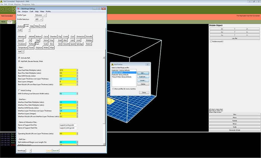
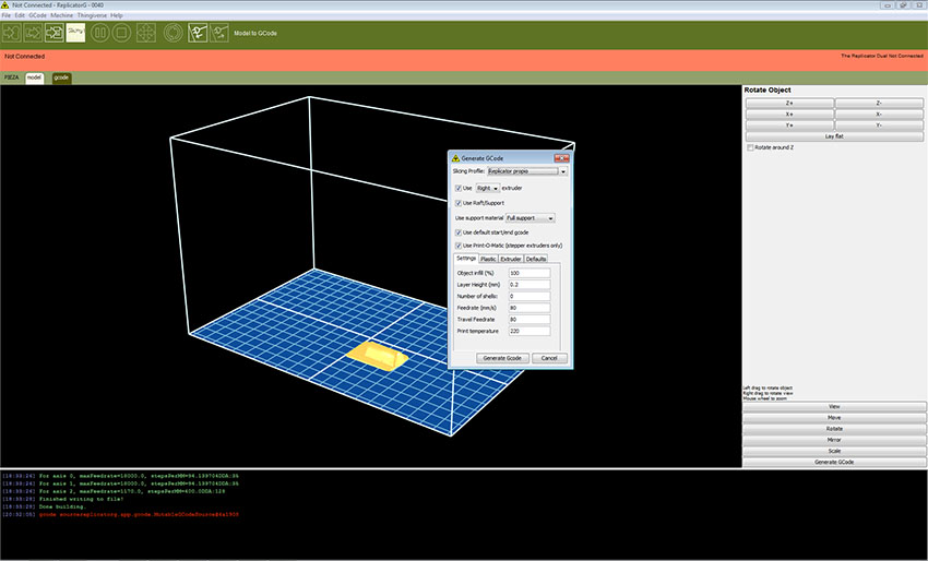
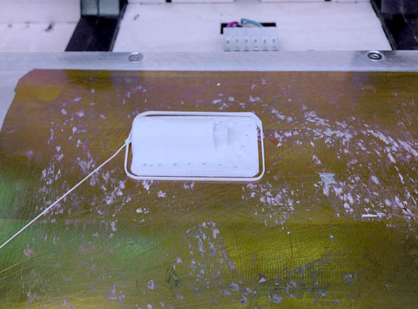
STEP 3: Print the corrected object For the 3D printing I use Makerbot Replicator machine with Rlicator-G software. In print options, I choose printing base in contact with the hot base of the machine (no raft) for better adherence of the piece, but with raft in holes to allow the machine to print it.
The piece is solid and Layer Heigh is 0.2 mm. I Generat the G code to print the piece.
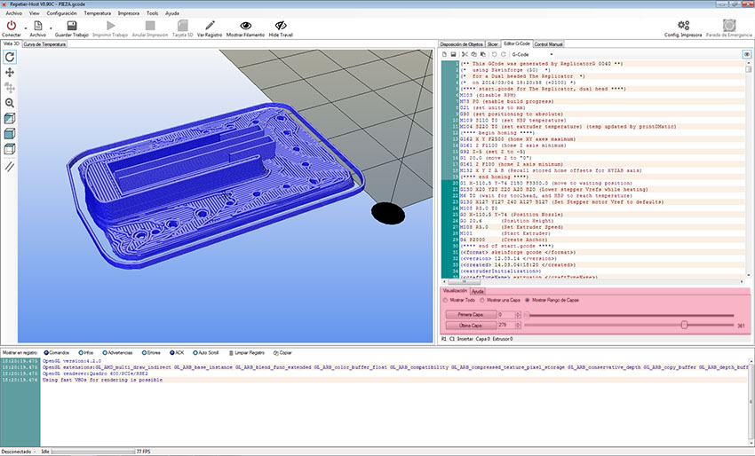
Before printing, to check the Layers to print, I use the software Repetier where I can see exactly how each layer will be printed. In my experience, when Repetier show a problem with the layers, the machine reproduce the same problem. Now that I know how the piece will be printed I can export the G-code to insert the SD card in the machine.
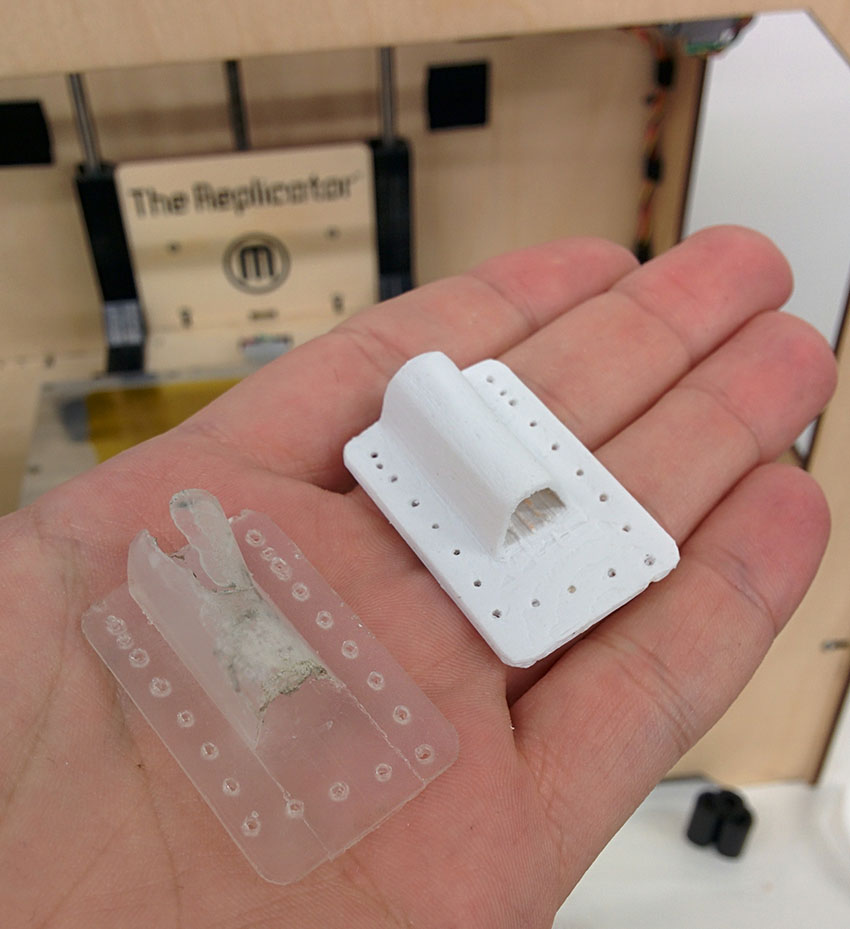
Now I have the new fixed piece to put it on my umbrella.
|