Home
About Me
Final Project Ideas
Computer-aided design
Computer-controlled cutting
Electronics Production
3D scanning and printing
Electronics Design
Molding and Casting
Embedded Programming
Computer Controlled Cutting (Router)
Input Devices
Composites
Interface & Application Programming
Output Devices
Networking and Communications
Mechanical / Machine Design
Applications and Implications
Invention, IP, Income
Project Development
Final Project


Embedded Programming

The task this week is to program the hello board.

Arduino IDE was installed on my computer.


Once the Arduino IDE was installed, attiny files were added to the hardware folder. 

Some issues were found when trying to install the drivers for FTDI.  Eventually, an executable installation file was found to install the drivers automatically.

Once everything was setup for Arduino IDE, another issue was found with the driver for the FabISP board.  The board was not recognized on the computer (using Windows 7), but a driver was found and installed.

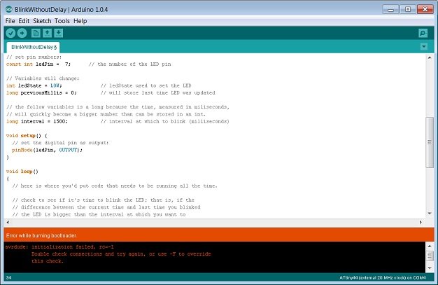
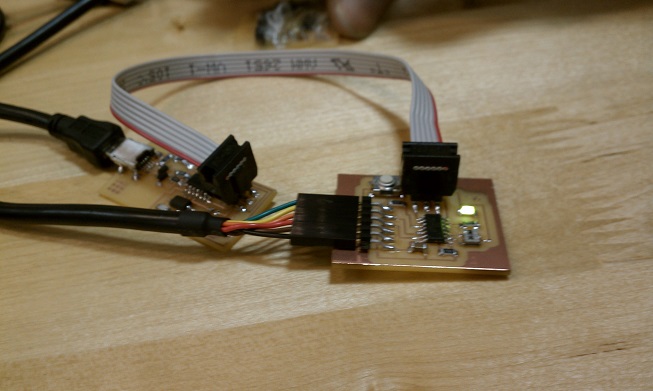
Connection to the new board became the new problem.  Double checking the components and connections on the board didn't produce any problems, checking the connections between the ISP and board, and the arduino IDE program, highlighted some errors.  In the Arduino IDE program, the 'serial port' setting was a big question.  A phone call to a helping has highlighted what the setting needed to be (viewing what connections were available relative with and without the new board connected determined which serial port to use).  The next issue was determining which direction the ribbon cable connector should be connected.  After a long review of the pins / wires in the connectors, it was determined that the cable I made needed to be flipped so the pins one each board would match. 

(Before this was found/determined, Arduino IDE had an error 'initialization failed, rc=-1     Double check connections and try again, or use -F to override this check.')  (shown in picture below)


Once all the issues were solved, the bootloader was successful, as were all the program variations tested.

The first test was to ensure the button worked.  Using the button example in arduino was successful (the led was lit, the button shut it off).  Understanding the pin numbers between arduino and attiny was needed before uploading the programs.


Uploading the blink example was also tested.  No videos were taken, but modifying the 'long interval' setting was fun to play with.  Changing the value to a large number (2 sec) was uneventful, but changing the blink to shorter intervals was interesting.  One thing observed was the rate of blinking visible to the eye was as short as 15 milliseconds.  Blinking faster (10 milliseconds) was not visible, and slower (20 milliseconds) was certainly noticeable.  Transferring this logic to a video formats didn't seem to make sense: a video captures/plays at 30 frames per second (which is not noticable to the eye), which means the 'picture' changes every 33.3 milliseconds.  If the blinking light was set to 33.3 blinks per second, the changes would be visible.  Could be comparing apples to oranges??    (Thought: the blink setting is really the interval that the led is either on or off (time between on to on is 2x the milliseconds setting), thus 15 milliseconds setting is similar to 30 frames per second.  Maybe?)