Home
|
| About Me |
| Final
Project Ideas |
| Computer-aided design |
| Computer-controlled
cutting |
| Electronics
Production |
| 3D scanning and
printing |
Electronics
Design
|
Molding
and Casting
|
Embedded
Programming
|
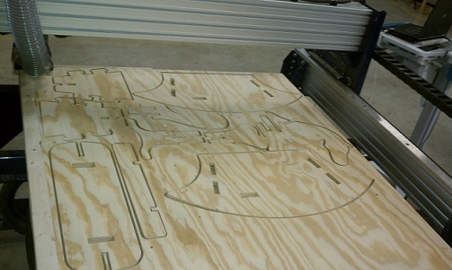
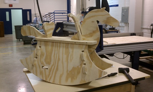
Computer
Controlled Cutting (Router)
|
Input Devices
|
Composites
|
Interface
& Application Programming
|
Output
Devices
|
Networking and
Communications
|
Mechanical /
Machine Design
|
Applications and
Implications
|
Invention, IP, Income
|
Project
Development
|
Final Project
|
|