output devices
Week 13 Overview
This week Fab Academy covered fabricating and programming output devices. This could be a number of things
but the most popular examples are: LED arrays, LCD screen, Motors (DC, stepper or servo), video and sound (speaker or Piezo).
There's also some pretty amazing work happening with shape changing materials. Here's examples of 2 of these:
- Moving bird creating with shape changing material http://fab.cba.mit.edu/classes/863.10/people/jie.qi/jieweek10.html
- pneumatically actuated materials https://vimeo.com/63591283
The assignment for the week was to:
- add an output device to a microcontroller
board you've designed and program it to do something
So what we needed to do this week was to make a hello world output board and program it.
Document what board I created and what it does.
Output Device - Stepper Motors
This week I decided to try and combined the light input sensor board and the stepper motor output board. First step is to understand how to work with stepper motors.
Typically machines use steppers for positioning & DC motors used for machines that needs high RPM, fast
rotation or gearing for things like fans that spin or window blinds that open.
- used for positioning but that you want to be able to rotate continuously
- for accuracy need to use closed loop control
- Steppers can turn continuously - no angle limitation - like a servo that can do multiple turns
- Steppers are for precision - can know exactly where it is all the time
- you get more control with a unipolar stepper
- when working with stepper motors you need to work out what the angle of rotation is per step
In the future I'd like to make something inspired by this work. I chose a stepper motor to work with because I wanted to use something that have precise angle of rotation & could rotate to 360 degrees. I decided to go for stepper unipolar, it's what we had in the lab. It works by sending pulses out to the different cables one at a time in an order. This order will send it clockwise and if it was the reverse order it would send it anti clockwise. We can see this in the wave file in c programming from the examples. This is what I used to get it working.
How Stepper motors Work
Two wires with a centre tap. Either end of the coil is connected to GND and
the centre tap is connected to power. Pulse this to get what you want.
- An image of how stepper motor works
- An adafruit tutorial 'All about Stepper Motors'
- Difference between unipolar and bipolar steppers
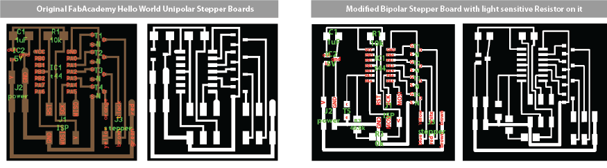
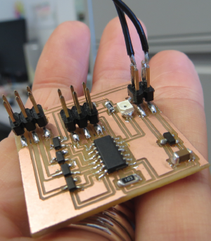
Step 1: Fabricating the Board
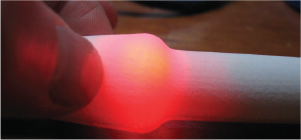
I decided to modify the hello world stepper board to include a light sensitive resistor.
The plan is to use this in the future to create a system where the motor reacts to the light in a room.
I modified the board in Eagle using the process I learnt in week 6 'electronics design' . Then I fabricated the board using the process
I learnt in week 4 'electronics production' .
Download Files:
Step 2: Programming the board
I did have an attempt at programming the board through arudino IDE using a
windows 64 bit operating system. I think working with stepper motors and then
trying to progamme in Arduino on windows was too much of a step so I reverted
back to Ubuntu and the hello world examples. Some useful links I used when I was
trying to program with Arudino and windows OS.
In the end I reverted back to program the board with a Hello world wave
example for the bipolar stepper board
using the FabISP on a ubuntu OS.
Download files I used for programming the bi polar stepper board:
Connect green and red together to ground (middle),
brown and black to one motor port (say M1) and
orange and yellow to the other motor port (say M2).
So in order, thats: brown - black - red&green - yellow - orange.
Then just use the example code that comes with the Adafruit Motor
Shield library. Otherwise, I could have alsod wire it up with some
transistors and used the Arduino Stepper library.
When we are programming the board we need the chip to be power by something.
We can use the FabISP to power them or batteries. In this case when the stepper
motor is running, a 5V battery powers it.
Some notes on how the make files work
While I was going through how to program with windows 64bit and arudino I didn't manage to get
my board from week 8 'embedded programming' programmed using both
(1) c and command line and
(2) arduino
Both worked fine. The only problems I has was that I needed to use aruduino version
1.0.3 to be able to select the programmer I wanted to use to programme the board.
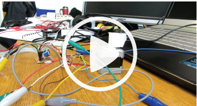
Final Working Stepper Motor
Reflections & Notes from the work on outputs
Reflections:
- on the board, there are two different power rails. One comes from the regulator output, is 5v and powers the attiny44. The other comes from the battery directly, goes to the regulator but also goes round to the stepper. The ground rail is common to them all
- Other thing is how n-type mofsets work - the three pins are gate, drain and source. gate connects to the microcontroller as this is what controls the current. Source goes to ground and drain goes to the stepper. So each coil on the stepper is connected to +9v (through the green/red wires) but not ground, except when the microcontroller output allows current to flow through a specific mofset: so the connections for the mofsets are right but worth noting how they work
- The phototransistor looks fine. When it is dark, the resistance is very high so essentially the pin is connected to vcc, the input is read as high. When it is very bright the resistance is very low, so current flows to ground and the input on the pin is read as low
Problems:
- When the fabISP is plugged into the board the cap is roasting hot. It started smoking when I had both the battery and the motor hooked up to the board. If I plug in the FabISP to the stepper board alone the Cap gets super hot? This happened while trying to programme it. The IC2 5V voltage regulator is getting very hot them I connect the FabISP with the ribbon cable to the stepper board. We think this is because when you power them 'backwards' (ie apply voltage to the reg output by attaching programmer, as opposed to applying voltage to the reg input from a battery). There probably should be a diode here if it's a known issue. In fact it might be due to the solder jumper not being removed from their ISP which means no power is transferred through the ISP header. A solution could be to remove that jumper on your programmer. voltage regulator was getting really hot because the voltage from the fabisp jumper connection was going straight to the out of the voltage regulator. A solution would be to put a diode here so it couldn't go to the out or take the jumper off the FabISP. Or add put new voltage regulator on the board
Week 13, Apr 17
Bipolar Stepper Board
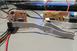
Programming the Stepper Board with the FabISP