Week 8 Overview
The embedded programming week covered how to start writing programmes from micro controllers.
The week looks at
1. how to write a programme for the processor and
2. how to communicate from the processor to the PC
Assignment
Read microcontroller data sheet
Take the board that we made in the electronics design (hello board) week and make it do something
The goal is programme the board we made
Get a programme loaded onto the board and make small changes to it. Idea is to get used to programming
Description of Embedded Programming Work
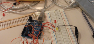
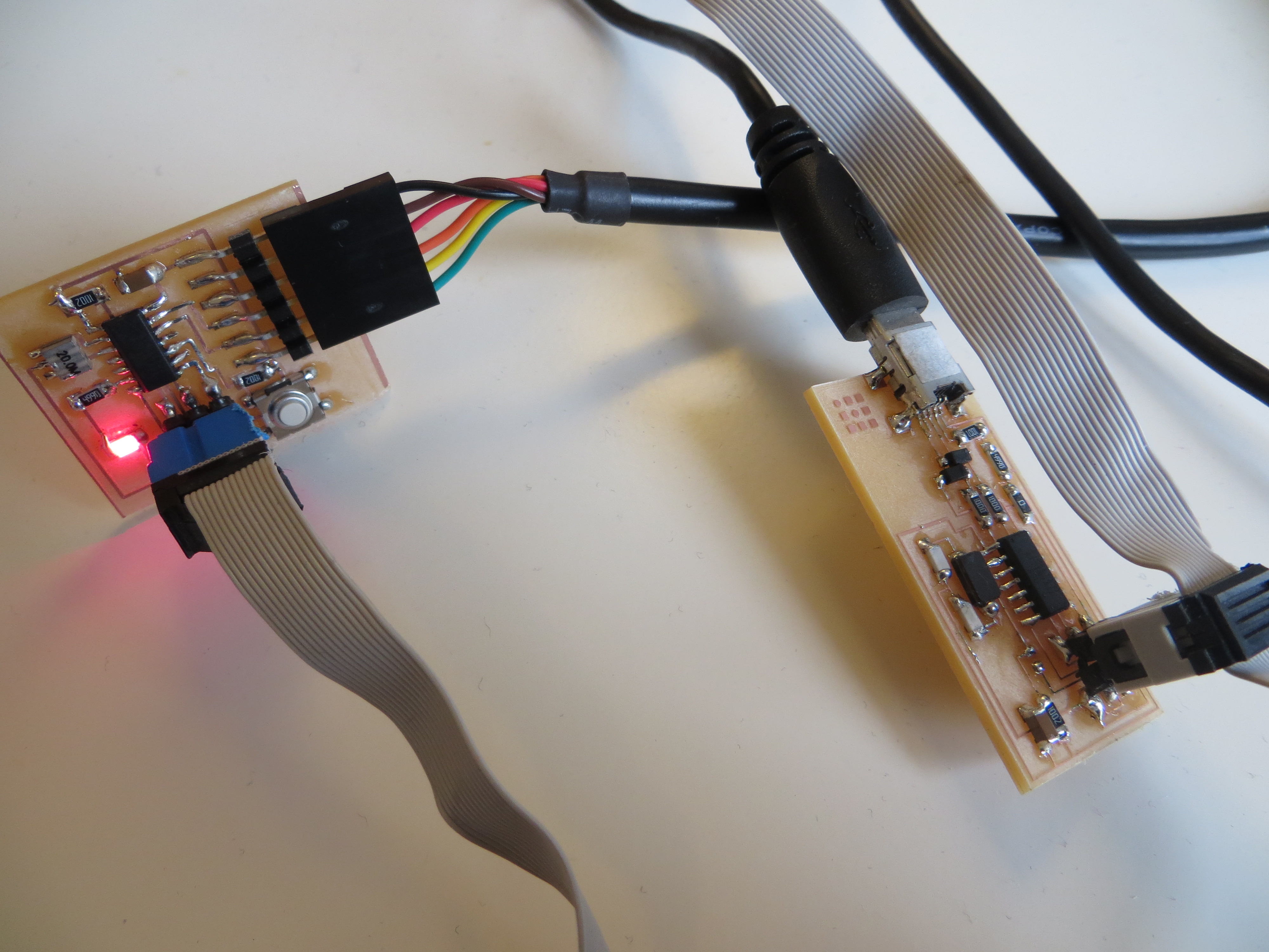
Hardware
- Ribbion Cable
- FTDI cable
- mini usb to usb cable
- FabISP board
- hello board
Software running on Ubuntu OS
- FTDI driver are already installed on ubuntu but normally would have to install these on mac or windows OS
- Arduino IDE Software - Link to Download the Arduino Software
- ATtiny board files in the tutorial
- GCC & avrdude - installation advice in thistutorial
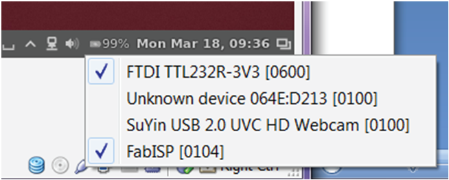
I'm using the ubuntu OS running on a windows machine through virtual box so this threw up a problem seeing the attached devices.
I had to make sure the devices plugged into the computer were selected in virtual box as shown in the pic below with ticks beside them.
Arduino Programming
Link to tutorial - Embedded Programming - Arduino IDE
Initially I had problems getting the Ardunio Serial port to recongise there was something attached to the compupter.
Joel indicted that other people were having similiar problems and Anna had written it into a
tutorial. It was
to do with the rules files.
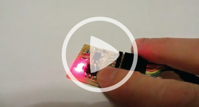
After getting the Ardunio IDE to see the board, I opened up the button example in Arduino and uploaded this to the board.
 After using the example button I wanted to make the LED fade up and down when you pressed the button using PWM.
I managed to change the code to fade up but fading down was a bit of a struggle.
I found
this example
online and edited my code to use parts of the online example I found.
After using the example button I wanted to make the LED fade up and down when you pressed the button using PWM.
I managed to change the code to fade up but fading down was a bit of a struggle.
I found
this example
online and edited my code to use parts of the online example I found.
// set pin numbers:
const int buttonPin = 3; // the number of the pushbutton pin
const int ledPin = 7; // the number of the LED pin
int x = 1;
// variables will change:
int buttonState = 0; // variable for reading the pushbutton status
void setup() {
// initialize the LED pin as an output:
pinMode(ledPin, OUTPUT);
// initialize the pushbutton pin as an input:
pinMode(buttonPin, INPUT);
}
void loop(){
// read the state of the pushbutton value:
buttonState = digitalRead(buttonPin);
if (buttonState == LOW) {
// fade up LED:
for(int i= 0; i > -1; i = i + x){
analogWrite(ledPin, i);
if(i==255){x = -1;}
delay(2);
}
x = 1;
} else {
// turn LED off:
analogWrite(ledPin, 0);
}
}
Programming with C
Link to tutorial "Hello Echo" -
Echo Keyboard Input Using C
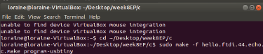
Following the tutorial above I ran into some problems trying to programming the ATtiny wth the Echo Code using
sudo make -f hello.ftdi.44.echo.c.make program-usbtiny
Ohad ran into similar problems and posted to use about it. Advising to replace
static char message[] PROGMEM = "hello.ftdi.44.echo.c: you typed \"";
with
const static char message[] PROGMEM = "hello.ftdi.44.echo.c: you typed \"";
in the 'hello.ftdi.44.echo.c file' which solved the problem.
Opened up the terminal and entered the following to start communication with the board
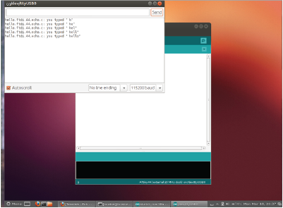
 opened up the serial monitor in Arduino IDE, set the baud rate to 115200, type letters & press send to communicate between the
PC and board using the FTDI cable.
opened up the serial monitor in Arduino IDE, set the baud rate to 115200, type letters & press send to communicate between the
PC and board using the FTDI cable.
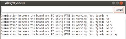
I made some little changes I made to the c code by altering the message that is output and
getting rid of the inverted commas.
//
//
// hello.ftdi.44.echo.c
//
// 115200 baud FTDI character echo, with flash string
//
// set lfuse to 0x7E for 20 MHz xtal
//
// Neil Gershenfeld
// 12/8/10
//
// (c) Massachusetts Institute of Technology 2010
// Permission granted for experimental and personal use;
// license for commercial sale available from MIT.
//
#include
#include
#include
#define output(directions,pin) (directions |= pin) // set port direction for output
#define set(port,pin) (port |= pin) // set port pin
#define clear(port,pin) (port &= (~pin)) // clear port pin
#define pin_test(pins,pin) (pins & pin) // test for port pin
#define bit_test(byte,bit) (byte & (1 << bit)) // test for bit set
#define bit_delay_time 8.5 // bit delay for 115200 with overhead
#define bit_delay() _delay_us(bit_delay_time) // RS232 bit delay
#define half_bit_delay() _delay_us(bit_delay_time/2) // RS232 half bit delay
#define char_delay() _delay_ms(10) // char delay
#define serial_port PORTA
#define serial_direction DDRA
#define serial_pins PINA
#define serial_pin_in (1 << PA0)
#define serial_pin_out (1 << PA1)
#define max_buffer 25
void get_char(volatile unsigned char *pins, unsigned char pin, char *rxbyte) {
//
// read character into rxbyte on pins pin
// assumes line driver (inverts bits)
//
*rxbyte = 0;
while (pin_test(*pins,pin))
//
// wait for start bit
//
;
//
// delay to middle of first data bit
//
half_bit_delay();
bit_delay();
//
// unrolled loop to read data bits
//
if pin_test(*pins,pin)
*rxbyte |= (1 << 0);
else
*rxbyte |= (0 << 0);
bit_delay();
if pin_test(*pins,pin)
*rxbyte |= (1 << 1);
else
*rxbyte |= (0 << 1);
bit_delay();
if pin_test(*pins,pin)
*rxbyte |= (1 << 2);
else
*rxbyte |= (0 << 2);
bit_delay();
if pin_test(*pins,pin)
*rxbyte |= (1 << 3);
else
*rxbyte |= (0 << 3);
bit_delay();
if pin_test(*pins,pin)
*rxbyte |= (1 << 4);
else
*rxbyte |= (0 << 4);
bit_delay();
if pin_test(*pins,pin)
*rxbyte |= (1 << 5);
else
*rxbyte |= (0 << 5);
bit_delay();
if pin_test(*pins,pin)
*rxbyte |= (1 << 6);
else
*rxbyte |= (0 << 6);
bit_delay();
if pin_test(*pins,pin)
*rxbyte |= (1 << 7);
else
*rxbyte |= (0 << 7);
//
// wait for stop bit
//
bit_delay();
half_bit_delay();
}
void put_char(volatile unsigned char *port, unsigned char pin, char txchar) {
//
// send character in txchar on port pin
// assumes line driver (inverts bits)
//
// start bit
//
clear(*port,pin);
bit_delay();
//
// unrolled loop to write data bits
//
if bit_test(txchar,0)
set(*port,pin);
else
clear(*port,pin);
bit_delay();
if bit_test(txchar,1)
set(*port,pin);
else
clear(*port,pin);
bit_delay();
if bit_test(txchar,2)
set(*port,pin);
else
clear(*port,pin);
bit_delay();
if bit_test(txchar,3)
set(*port,pin);
else
clear(*port,pin);
bit_delay();
if bit_test(txchar,4)
set(*port,pin);
else
clear(*port,pin);
bit_delay();
if bit_test(txchar,5)
set(*port,pin);
else
clear(*port,pin);
bit_delay();
if bit_test(txchar,6)
set(*port,pin);
else
clear(*port,pin);
bit_delay();
if bit_test(txchar,7)
set(*port,pin);
else
clear(*port,pin);
bit_delay();
//
// stop bit
//
set(*port,pin);
bit_delay();
//
// char delay
//
bit_delay();
}
void put_flash_string(volatile unsigned char *port, unsigned char pin, PGM_P str) {
//
// print a null-terminated string from flash
//
static char chr;
static int index;
index = 0;
do {
chr = pgm_read_byte(&(str[index]));
put_char(port, pin, chr);
++index;
} while (chr != 0);
}
void put_ram_string(volatile unsigned char *port, unsigned char pin, char *str) {
//
// print a null-terminated string from SRAM
//
static int index;
index = 0;
do {
put_char(port, pin, str[index]);
++index;
} while (str[index] != 0);
}
int main(void) {
//
// main
//
static char chr;
static char buffer[max_buffer] = {0};
static int index;
//
// set clock divider to /1
//
CLKPR = (1 << CLKPCE);
CLKPR = (0 << CLKPS3) | (0 << CLKPS2) | (0 << CLKPS1) | (0 << CLKPS0);
//
// initialize output pins
//
set(serial_port, serial_pin_out);
output(serial_direction, serial_pin_out);
//
// main loop
//
index = 0;
while (1) {
get_char(&serial_pins, serial_pin_in, &chr);
//loraine - commented out the below line
// const static char message[] PROGMEM = "hello.ftdi.44.echo.c: you typed \"";
const static char message[] PROGMEM = "Commication between the board and PC using FTDI is working. You typed: ";
put_flash_string(&serial_port, serial_pin_out, (PGM_P) message);
buffer[index++] = chr;
if (index == (max_buffer-1))
index = 0;
put_ram_string(&serial_port, serial_pin_out, buffer);
//loraine - commented out the inverted comma
// put_char(&serial_port, serial_pin_out, '\"');
put_char(&serial_port, serial_pin_out, 10); // new line
}
}
Important Points from this week to remember for the future
- Bootloader is a special programme that loads programs.
- AVRDUDE implements in software the logic of programming. There's a communication protocol to load a programme &
AVRDUDE is software implement of that protocol. This is the software that will talk to the ISP to load the programme onto the hello board.
- Assembly code controls every aspect of what the processor will execute. Hex is the raw code that gets sent to a chip
- FTDI cable gets computer talking to the processor to send back information to the computer you need to use the FTDI cable.
Turns on and off pins and sends and receives to computer using RS232
- On the hello board Rx is for receiving data and Tx is for sending data
- Setting the fuses gets the processor to tell the time by using the external crystal
- Every pin on the microprocessor can be an input or an output pin
- Make files builds the files and loads them