electronics design
Week 6 Overview
The sixth week covered electronics design which mainly gave us an overview of the main components we'll be working
with, an introduction to some software that is used for creating schematics and layout of pcb's before milling.
The assignment for the electronics design week was to make a pcb with an input and an output. In this case we had a board
design as a guideline that we altered to include a LED and a button, as well as the appropriate components to support
the circuits for these.
- Link to this weeks academy information page - electronics design.
- Link to a tutorial I followed to guide me through the process of designing and producing the pcb.
Description of Process
Took me a while to get used to how to use Eagle but it's a great tool for creating the schematics and the data
to mill the board on the Roland. I never used a tool like this before, I've always struggled to just do line drawings on a
bit of paper.
First of all I created the schemtatic below
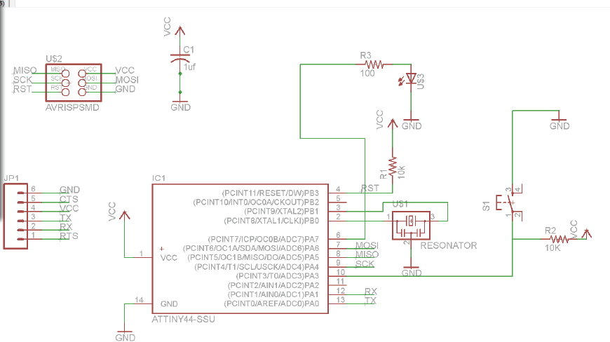
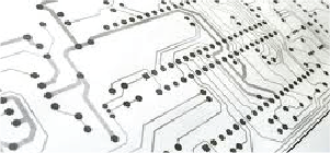
From there I altered the position of the components and added in the traces in the board for milling
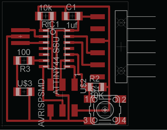
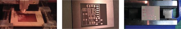
Then I exported the image as a png having the parts of copper I didn't want mill in white and what I do want mill
in black.

Milled out the board using slightly adjusted setting from the FabISP board
Tool - Engraving - 20 Deg Tip 0.15
Pass Depth 0.15mm
Stepover 0.128 (85%)
Feedrate 10
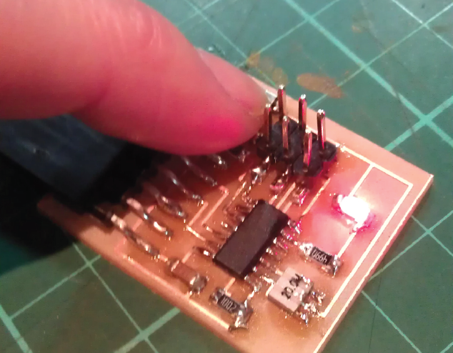
Soldering on all the components to the board
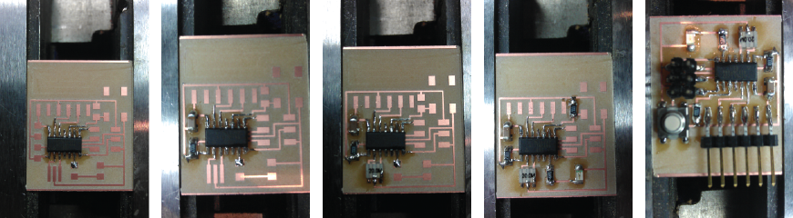
Final Board
Final Board and IT WORKS!! AMAZING!
Week 6, Feb 27